Week 9 - Challenge 3 - Bumper
AIM
Create the Bumper Plastic component by the given Class-A surface. To begin with, the tooling axis for the given Class-A Surface might be created meeting the requirements of the draft angle and at the end perform the Draft analysis on the model.
INPUT GIVEN
- Class A surface
- Thickness 3 mm
- Draft angle 3 degree
TOOLING AXIS
Tooling axis represents the opening and closing of the mold core and cavity during the manufacturing of the components. A plastic product designer should consider the best tooling direction to cutdown the cost of the component very less.
Method opted for creating tooling axis for the bumper
- Check the best tooling direction for the given surface.
- We can find out the best tooling direction by cross checking all the three axes.
- Here we can find out that the best tooling direction for the pumper class-A surface is along x-axis direction
- The method I choose to create the tooling axis is first extracted a surface and create a midpoint on that surface. The introduced an axis system on that point.
- Then created a with the point and direction along x axis.
- Here both the outer flanges have 5.1-degree draft with respect to the axis created. Hence going with the axis created will not make any difficulties during the draft analysis.
- Another method is by creating intersection along y direction. And then create lines on the walls and then create a bisecting line with the lines on the wall and point created earlier. We will get an axis which will satisfy the draft analysis requirement.
CREATION OF CLASS B SURFACE
Cass-B surface means thickness of a part it is not visible and is inside part. In other words, Class-B surface is a surface below a certain thickness from the class-A surface. This is the surface that contains engineering aspects of a model.
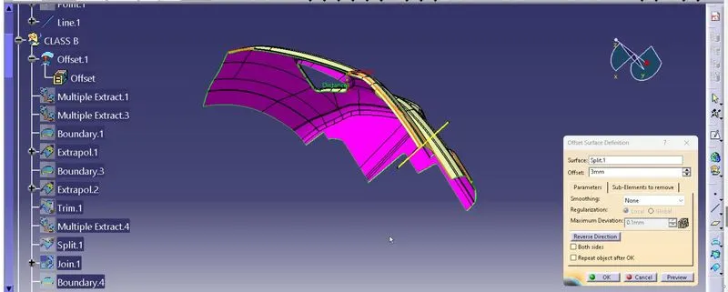
- Offset the class-A surface to 3mm inward direction.
- Rework on the patches and discontinuity of the offset surfaces using the features like extract, multi-extract, sweep, multi-section surfaces, extrapolate.
- To ensure the continuity of the Class-B surfaces check the boundary command to find out the boundary.
- Hence class-B surface creation is done.
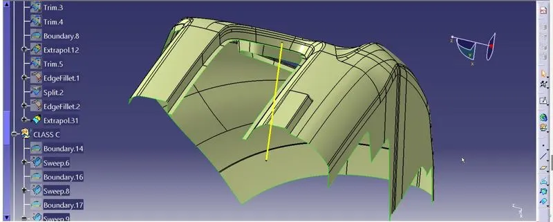
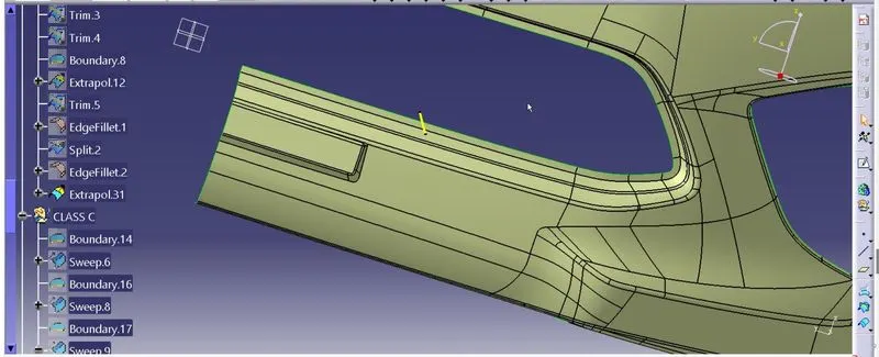
The Areas where the B-surface has issues are corrected by closing them using commands like Multi section,Sweep,Offset and extract.
Finally all the created surfaces are trimmed or joined together with offset surfaces done earlier. This created a single surface which will act as the final B-surface.
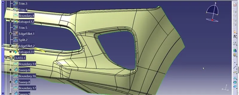
CREATION CLASS C SURFACE
Surface that joins class-A and class-B surfaces is class-C surface. Class C is often specified for interior surfaces not readily visible, surfaces that will be covered by another part when assembled
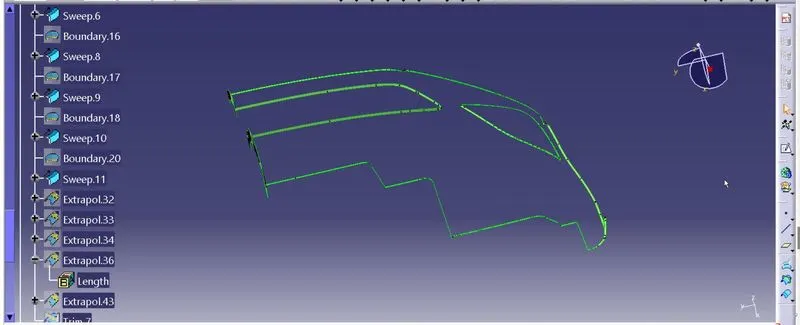
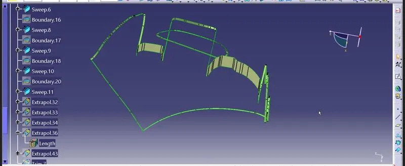
Since it is a complex class-A surface, we cannot simply create the class-A boundary curve and sweep it at one shot. Hence, we need to create smaller curves using multi-extract command and then create sweep of 90 degree with reference to the surface option. sweeps at the midportion of the bumper should have a 93 degree vaue to pass the draft analysis.
- Extrapolate and trim off the sweep surface corners at the required edges.
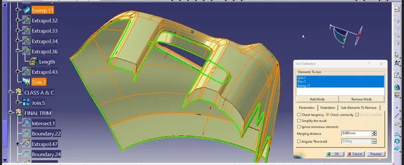
- Join the sweeps using the join command and the class-c surface is created.
JOINT CLASS A &C SURFACE
- First step is to join the CLASS-A surface with CLASS-C surface.
- Then Trim the Joined surface with CLASS-B surface to achieve the final Bumper surface.
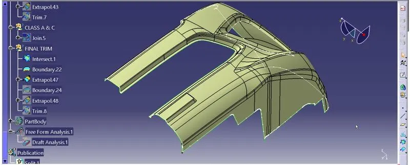
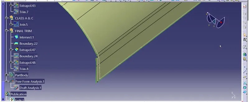
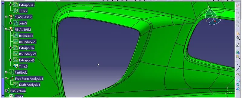
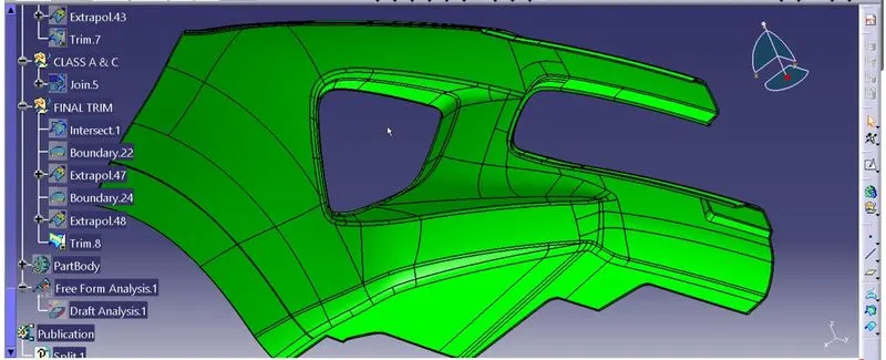
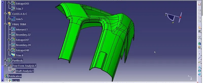
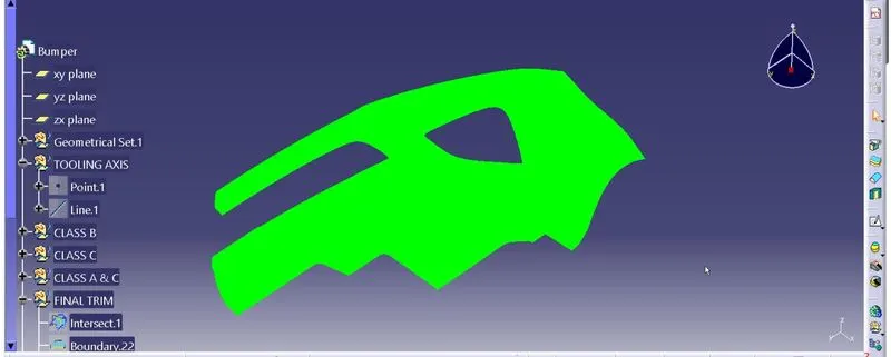
FINAL TRIMS FOR BUMBER
CLOSED BODY
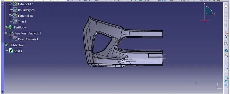
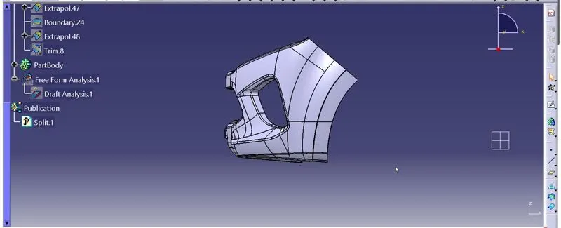
DRAFT ANALYSIS OF PART BODY
The final solid part body has to be analyzed using Draft analysis. This is done to check if all the areas of the body are satisfying the draft angle which is 3 degrees.
A draft angle is a taper applied to the vertical walls of the injection-molded component to assist with releasing the part from the mold.Draft angles are a required feature of injection-molded custom parts. A functional part for injection molding has to have draft angles that face both the cavity and core sides. This will reduce the risk of damage to the parts and ensure that they can be ejected from the machine.
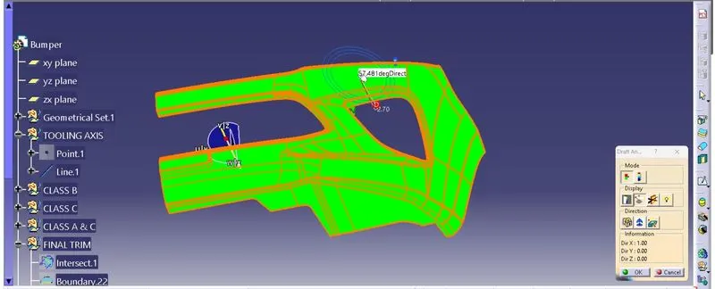
- Change the view mode to material shading
- Align the Compass with Tooling axis.
- Lock the draft direction and perform the Draft analysis.
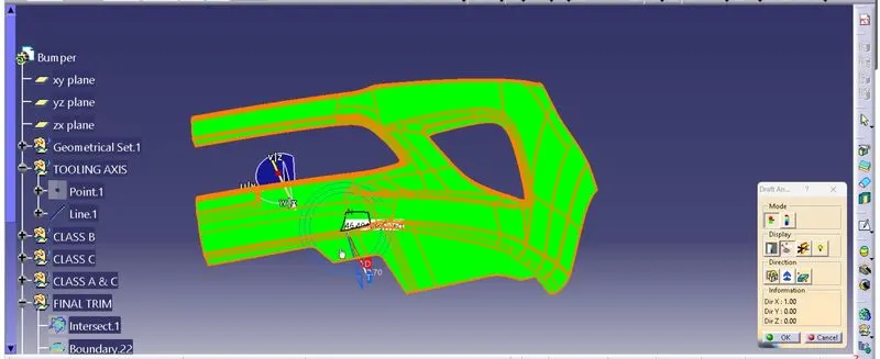
CONCLUSION
I have successfully created the class-B and Class-C surfaces of Bumper using the given Class-A surface along with the tooling axis in the CATIA surface workbench.