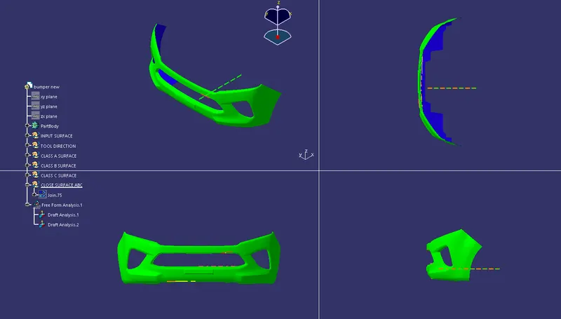
Week 9 - Challenge 3 - Bumper
AIM:TO CREATE BUMPER PLASTIC PART THROUGH GIVEN CLASS A COMPONENT
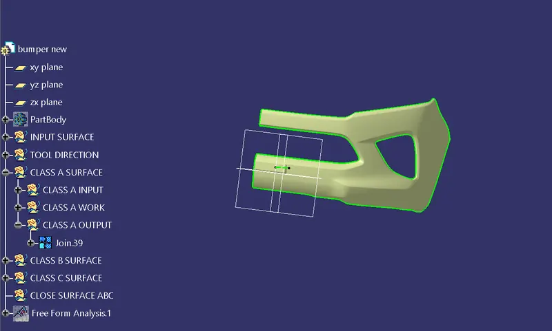
STEP 1:ENSURE CONNECTIVITY OF GIVEN CLASS A SURFACE
The given CLASS A surface is checked for its connectivity using join command and the CLASS A surface is repaired for any sharp edges present using tools like multi-section and blend tools
STEP 2:TOOLING AXIS CREATION
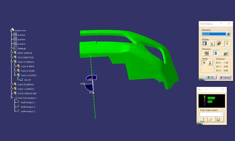
Tooling axis is created by normal to surface method,A point is created on a surface and and a line is created in point direction in appropriate direction and a draft analysis is carried out to ensure the direction on given CLASS A surface.
STEP 3:CLASS B SURFACE CREATION
The input for CLASS B is the output of CLASS A and it is offsted to a desired distance of 3mm and further repairing works carried out on CLASS B surface and made it free of any sharp edges and extrapolated it a little bit to ensure intersection while trimming with C surface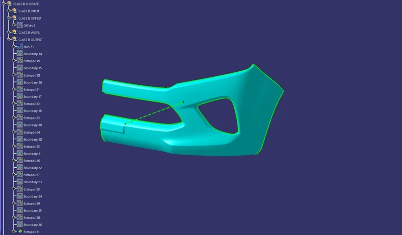
STEP 4:CLASS C AND CLOSURE SURFACE CREATION
The input for CLASS C surface creation is CLASS A surface and CLASS C surface is created part by part using sweep tool and its different options like with draft direction and with reference surface and then the C surface is trimmed with A and B inorder to get the closure surface.A side of it kept opened to mirror and create the full object.
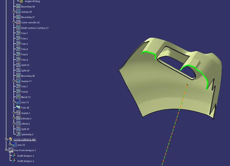
STEP 5:MIRRORING AND CREATING FULL BUMPER
The current part is mirrored with respect to zx plane to get the complete object and then using closure surface made to a solid body.
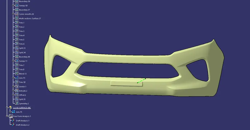
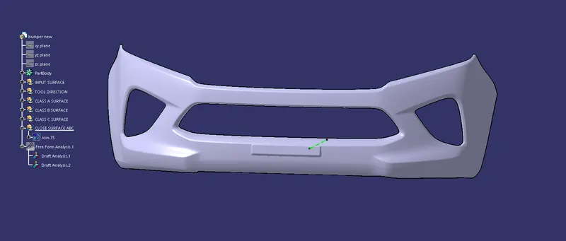
STEP 6:DRAFT ANALYSIS ON FINAL BODY
Draft analysis is carried oput on the final body using the alrteady created tooling axis.
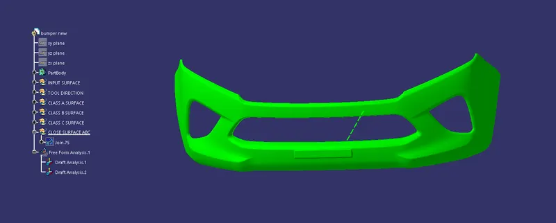
DIFFERENT VIEWS: