Week 9 - Challenge 3 - Bumper
Aim: -
Create the Bumper Plastic component through the given Class-A surface. To begin with, the tooling axis for the given Class-A Surface should be created meeting the requirements of the draft angle and at the end perform the Draft analysis on the model.
Objective
- To create a tooling direction
- To perform draft analysis for given A-Surface and prepare the final close body.
- To design the Bumper plastic component by creating the B-Surface and C-Surface using the given Class-A surface.
- Take the Thickness of the component to be 3 mm.
Introduction: -
They are designed to absorb impact onto the front and rear of vehicles and minimize low-speed collision damage. Today, standard passenger's vehicle bumpers have a rigid reinforcing bar under the outer cover, with sections of compressible foam or plastic underneath.
Design Methodology
Skin data would be provided to us by the styling team to us
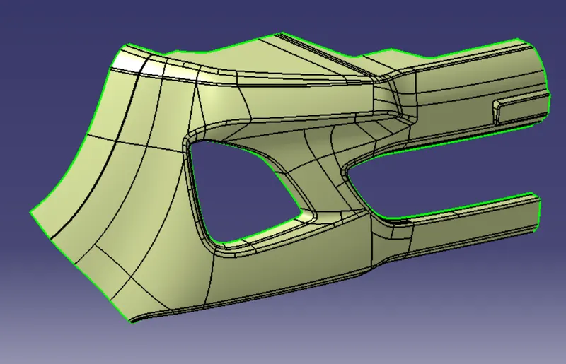
Class-A surface means visible surface. It gives the aesthetic of the component which is created by the styling team and gives to the part design engineer to create the part with all engineering aspects.
Class A surface
- Analyze the class A surface through visual inspection.
- To make sure that the given surface has no gap in between them.
- We can check it also with the help of Join or boundary commands.
Tooling Axis
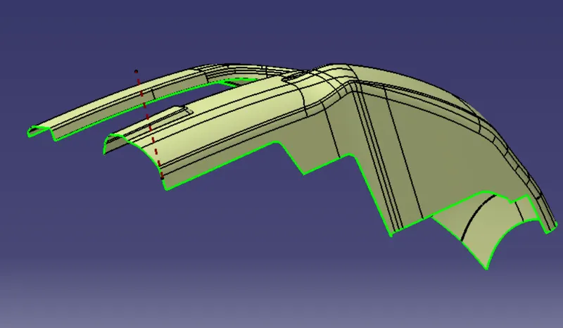
- Check the best tooling direction for the given surface.
- We can find out the best tooling direction by cross checking all the three axes.
- Here we can find out that the best tooling direction for the pumper class-A surface is along x-axis direction
- The method I choose to create the tooling axis is first extracted a surface and create a midpoint on that surface. The introduced an axis system on that point.
- Then created a with the point and direction along x axis.
Draft Analysis
The Draft Analysis is a command enables you to detect if the part you drafted will be easily removed. This type of analysis is performed based on color ranges identifying zones on the analyzed element where the deviation from the draft direction at any point, corresponds to specified values.
Draft analysis is done after determining the tooling axis, draft analysis is used to check whether the minimum draft (3 degrees) is maintained or not.
Class B surface
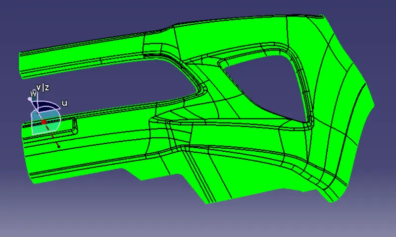
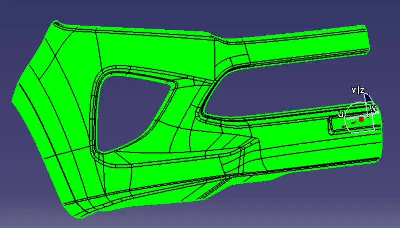
The surface which is back side of Class A surface is called Class B Surface. Mostly it not visible. It is created with the help of Class A surface with some distance (thickness) like 3mm etc.
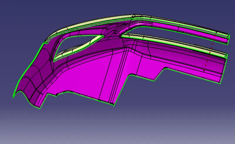
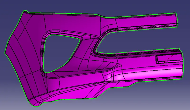
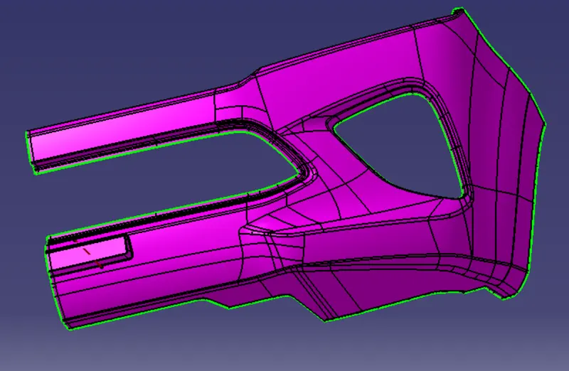
Creation of C-Surface:
Surface that joins class-A and class-B surfaces is class-C surface. Class C is often specified for interior surfaces not readily visible, surfaces that will be covered by another part when assembled
Is created with help of A-Surface by using the Sweep and Boundary command.
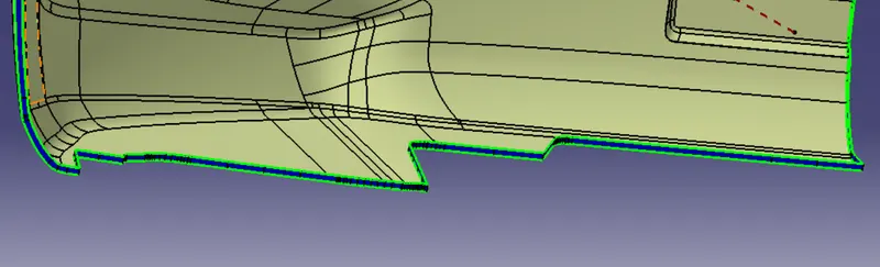
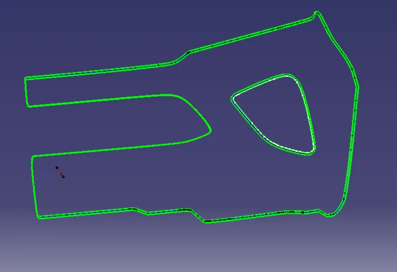
After creation CLASS A,B&C, The CLASS A & C join this will be shown in fig
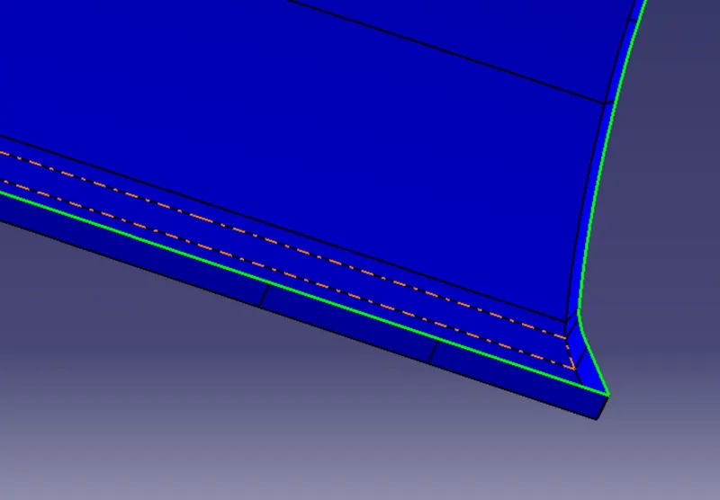
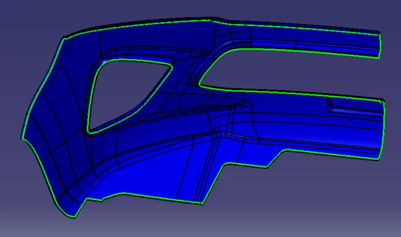
After joining A & C then final join B surface for making closed body
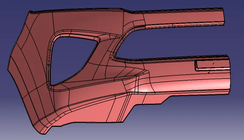
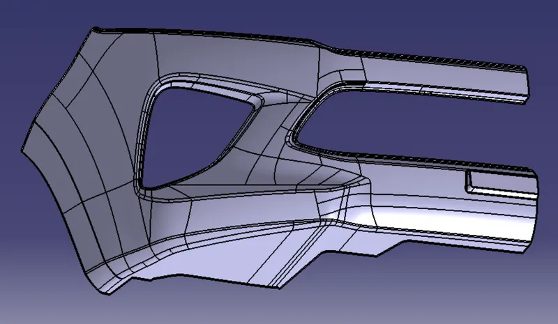
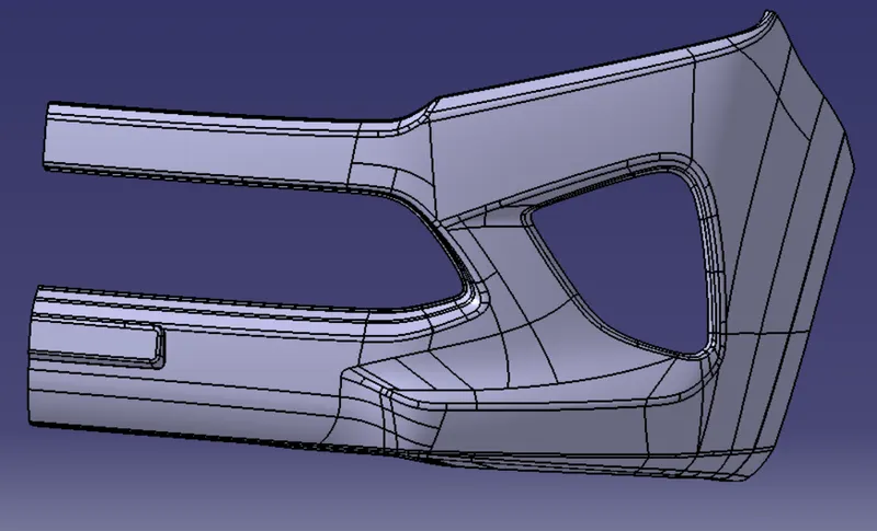
Draft analysis
After doing a closed surafce again doing draft analysis for manufacturing purpose.
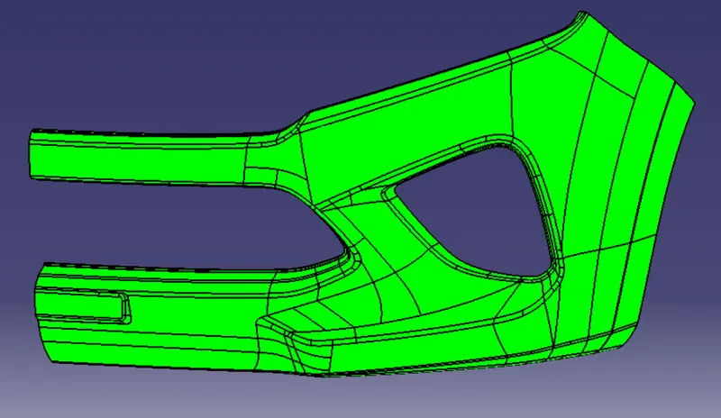
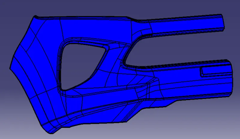
Conclusion
I have successfully created the class-B and Class-C surfaces of Bumper using the given Class-A surface along with the tooling axis in the CATIA surface workbench.