Week 8 - Challenge 1 - Base Bracket Design
BASE BRACKET DESIGN
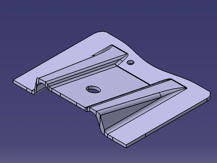
To create a Base Bracket Plastic Component through a given Class A Surface and perform Draft Analysis on the final plastic component.
Procedure to create closed surface
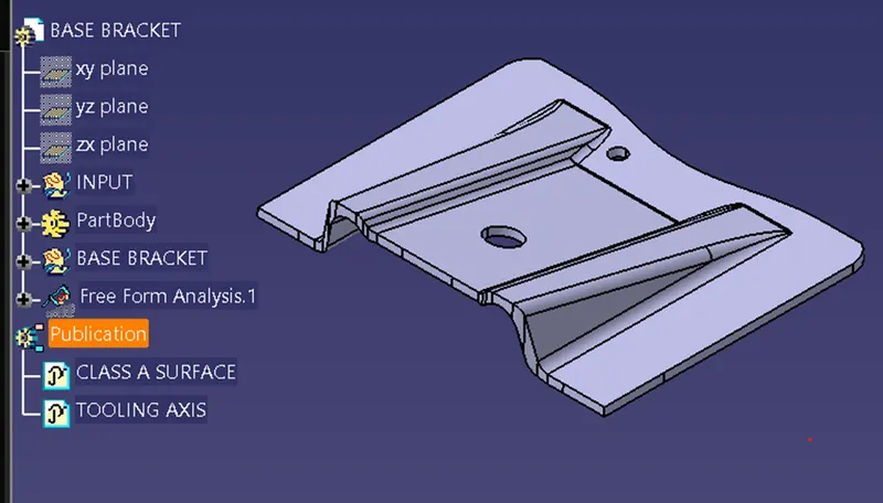
- First draw TOOLING AXIS
- Then create a DRAFT ANALYSIS
- After that create CLASS A surface and CLASS B surface.
- Then create final closed surface with the help of all surface just like CLASS A, CLASS B & CLASS C
Tooling axis
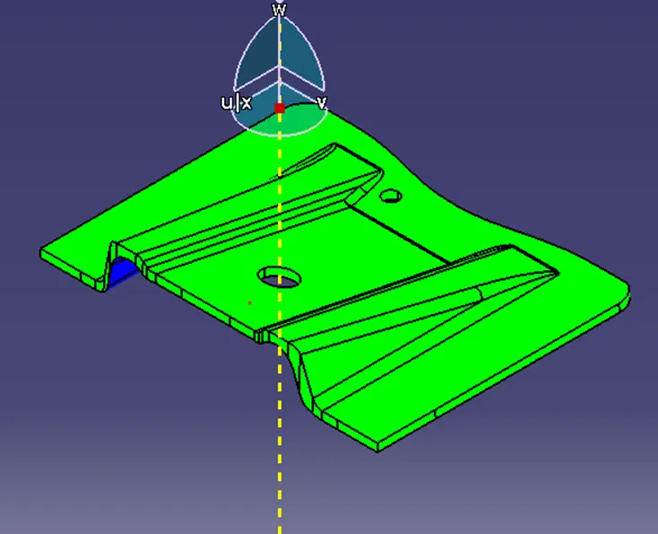
The tooling axis is the direction of drawing a sheet metal where the finished component is easily ejected on a particular direction and axis. The tooling axis is important for removing the material when finished.
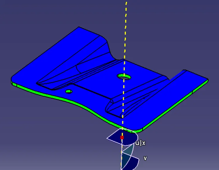
Tooling axis is creating by BISECTING method which is shown in figure.
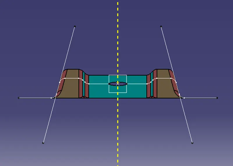
In the above images DOTTED LINE is TOOLING AXIS
Draft analysis for CLASS A surface
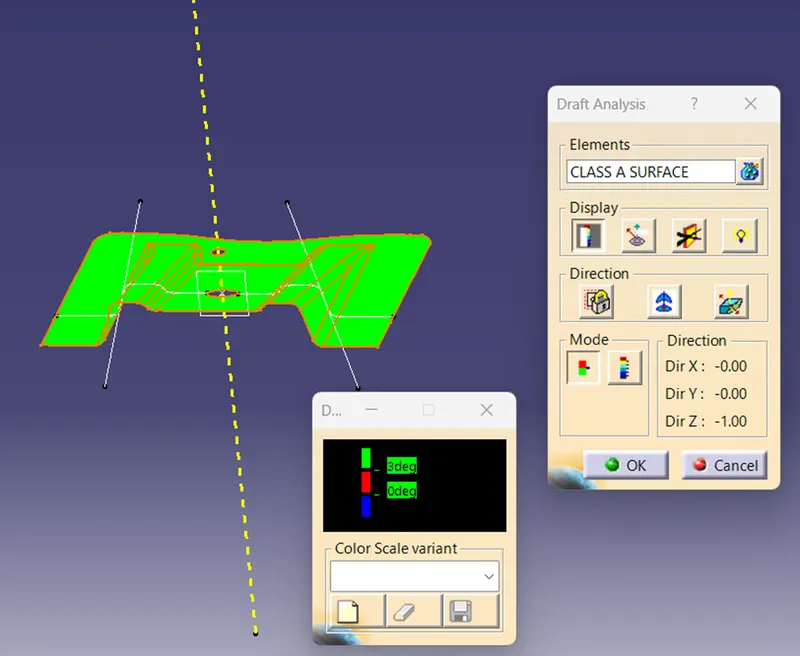
The analysis is done for 3-degree draft, so as can been seen all the surfaces are more than 3 degrees but Draft angle should maintain minimum 3 degree not less than that.
CLASS B SURAFCE
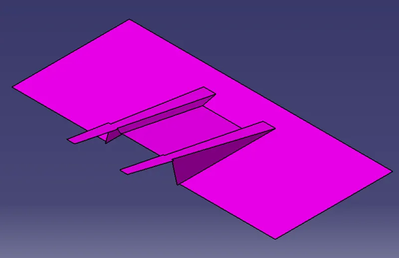
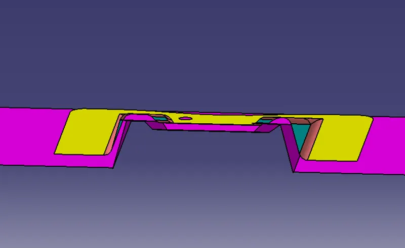
To create the class B surface, I considered the entire surface has 3 parts 'Rib-1, Rib-2, and Base surface'. If we directly offset the class A surface, fillets may lead to cause an error, to avoid the errors we need to extract the surfaces and untrim the extracted surfaces and extrapolate those untrimmed surfaces with point continuity. Now trim those extrapolated surfaces to the required shape. And finally, fillets were given to the final trim.
CLASS C SURAFCE
CLASS C surface is generated with the help of boundary which is created by CLASS A surface with the guide reference TOOLING AXIS and draft angle is 3 degree
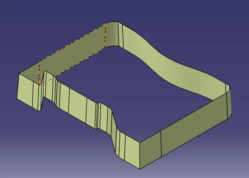
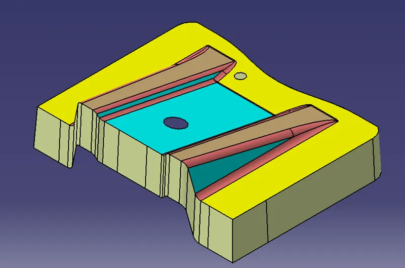
CREATING JOINING
CLASS A+CLASS C
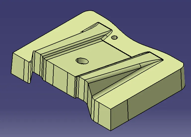
CLASS A+CLASS C+CLASS B Final trim
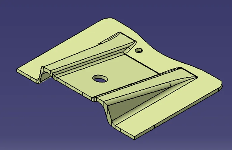
CLOSED SURFACE
CONCLUSION