Week 9 - Challenge 2 - Switch Bezel Design
Objective
The objective of the project is to design the switch bezel and to do a draft analysis for it by creating the required tooling direction with the help of Bisecting method
Design Consideration
- Class – A surface should be aesthetically smooth and good.
- Class – B surface should have all the supporting features like ribs.
- Parting Line should coincide with the B surface since flashing couldn’t affect the aesthetic of Class – A.
- Class – C surface should also pass the draft analysis.
Procedure to Creating Class-A Surafce:-
- A Reference Point is created along the Surface zero and new Axis system is created
- The X Direction along the Class A and Y direction along the Class A were used to create Tooling direction
- Finally the Tooling axis is created by bisecting the two lines
- The tooling Axis determines the direction of Class C boundary swept with draft direction.
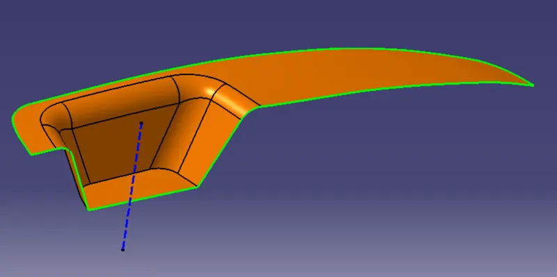
Creation of Class B Surface:
- For creating the class-B surface the required surface except the offset surface have been extraced and then untrimmed all the surface.
- Then all the surface have been extrapolated to get intersections between them.
- Since the thickness of the switch bezel is 3mm.
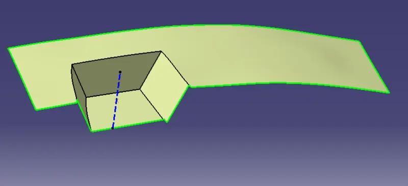
After radius from class A surafce
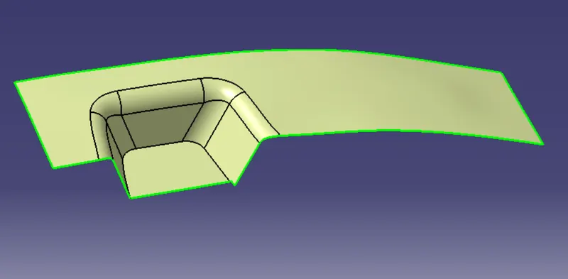
Creation of Class C Surface:
- The Next step is to from the C surface which is an intermediate surface between A and B and is used to give the closed surface appearance to the design
- The C Surface is swept using the profile as boundary line of Class A which is the Guide curve with a subtype along draft direction.
- The Direction of the sweep is the tooling direction formed earlier
- The draft angle for the sweep operation is provided which is 3 Degree and surface is swept for length above the thickness of the specified part
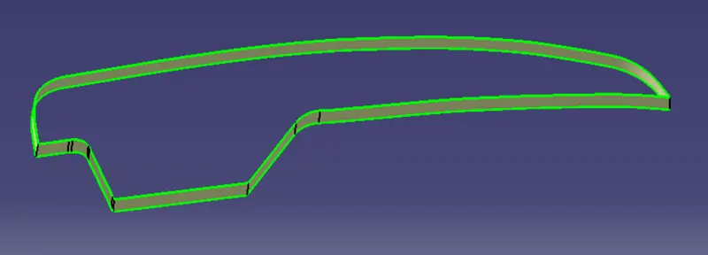
After all this process CLASS A & CLASS B surface are join together with the join command.
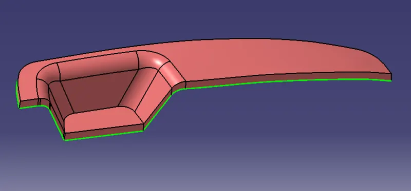
After this join CLASS A & CLASS B & CLASS C and peerformed closed body
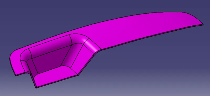
Closed body using Cloased surface
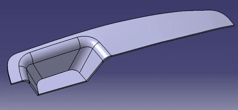
Procedure for Draft analysis
- First of all the compass was activated and placed with the tooling axis by dragging the red pointer and then locked it.
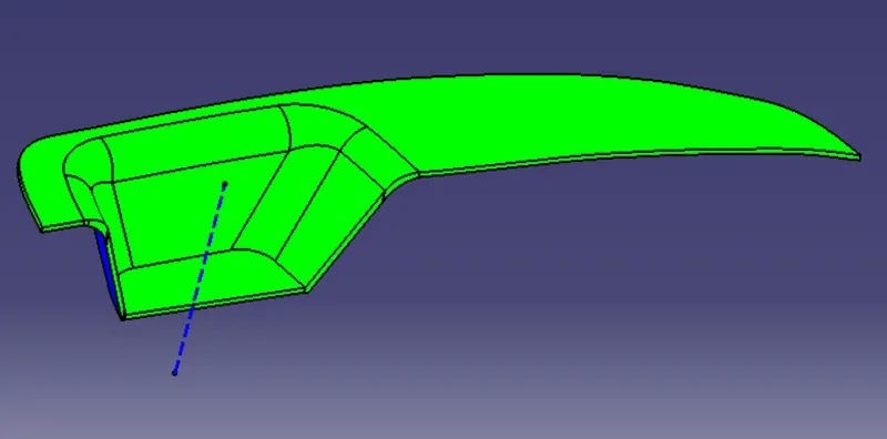
- Then, by selecting the quick analysis mode, the nominal value will be 3 degrees and checked for the component's draft angle.
- The green colour area shows that it satisfies the 3-degree draft angle. If not satisfied then by using the Running point tool the area is measured and then altered to get a successful draft for the created tooling direction.
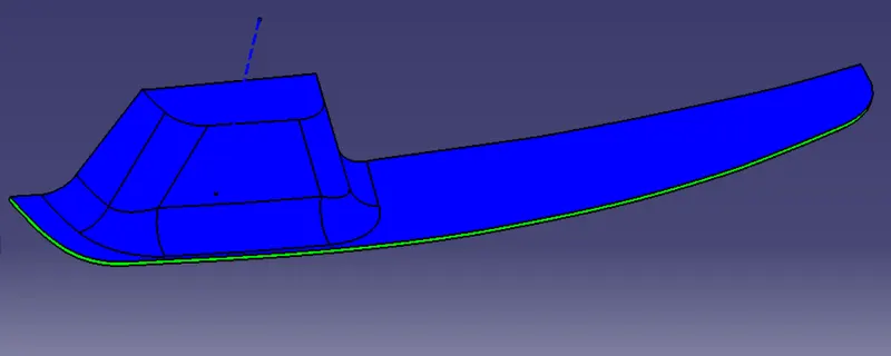
Conclusion
Finally the Class – A, B&C surfaces with the Tooling Direction have been Published and the Switch Bezel is moved on to the designing of the next operation – the creation of B-side features.