Week 9 - Challenge 3 - Bumper
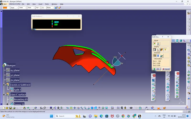
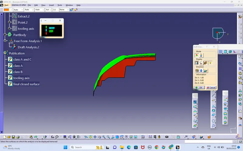
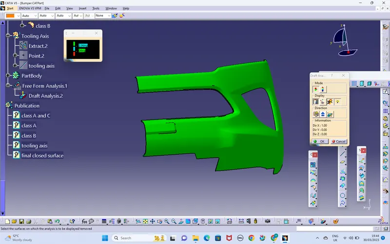
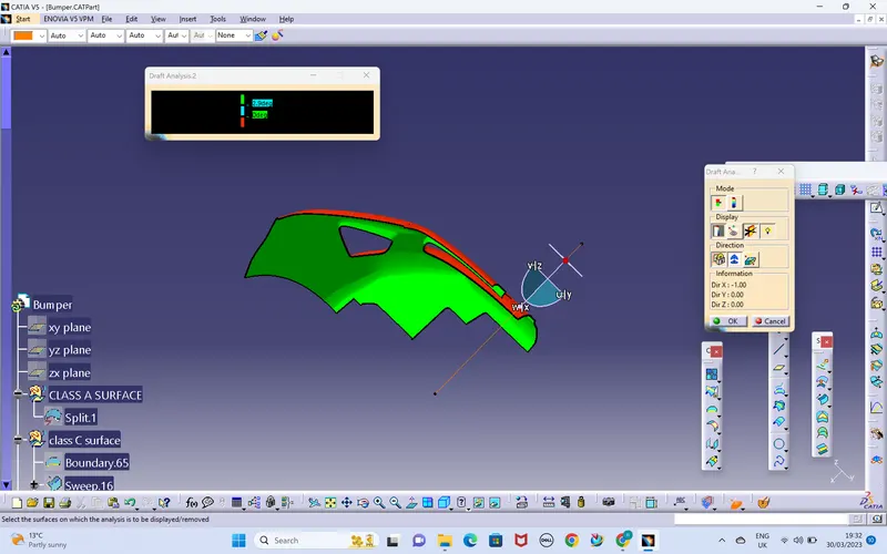
- The draft analysis is carried out on the given class A by using the command called featured draft analysis.At this stage we can analyse all the faces with the draft angle reference,if the draft angle is not sufficient we must proceed accordingly,In this case the draft angles was sufficient and proceded for the decision of tooling direction.
- For the given class A surface the tooling direction would be on the flat surface because the only profile is having the flat surface .i have decided to be the tooling direction on normal to the flat surface by creating the point first and line would be the axis of tooling.
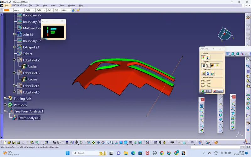
- As soon as the creation of the tooling axis the offset surface will be taken from the class A and few fillets were not driven by the cass A and i worked on the fillets by using multiple extract and creating the boundaries,later extrapolation is occured to create the fillets by using fillet command.
- After following the same process for all the surfaces which are not carried over on the B surface from will be done.
- The next would be creation of the surface C,with the draft by given angles,on the flat surfaces which is parallel to the tooling direction,and extrapolated to trim the final surfaces. finally join command is used to join the C abd A surfaces,and trimmed with the B surfaces.
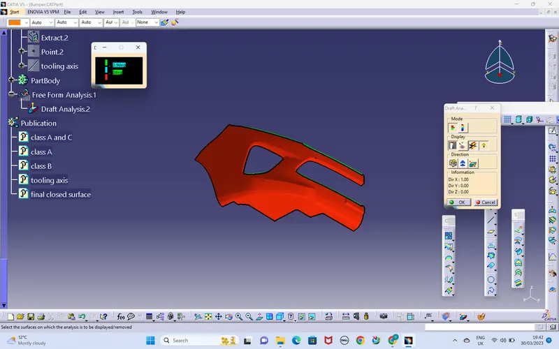
- Checked the surfaces are closed properly by using boundary command,if i grt the error message then it is a closed boundary,and applied the closed surface to get the solid body.
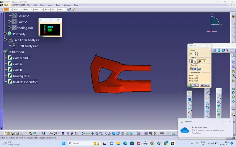
- The draft analysis is carried out on the solid surface on both core and cavity side wheather the solid is mouldable or not.