Week 9 - Challenge 3 - Bumper
BUMPER DESIGN
OBJECTIVE : To design the BUMPER by creating a class B and C surfaces using the given class A surface, creating Tooling axis and performing Draft analysis.
CREATION OF TOOLING AXIS
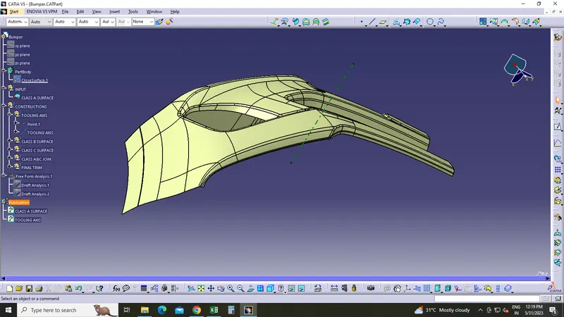
- First checked the best suitable direction for Tooling axis using the compass.
- And found that in X axis most of the surface patches are clearing.
- Generally bisecting method is used to create tooling axis, but in this case a line normal to the surface is created in one of the boundary of the component in X direction.
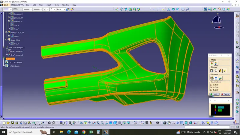
DRAFT ANALYSIS ON CLASS A SURFACE
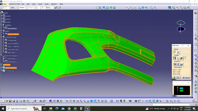
- First view mode is changed to material mode.
- INSERT> ANALYSIS> FEATURE DRAFT ANALYSIS
- Dragged the compass to tooling axis and then activated the compass, placed it properly along the tooling axis and locked its position.
- Then selected the component and activated draft analysis.
- Changed the minimum draft to 3 degree and the component has cleared the draft with respect to the tooling axis created.
- Then both the Tooling axis and class A surface were published.
CREATION OF CLASS B SURFACE
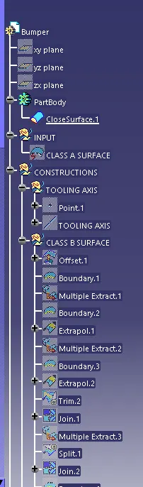
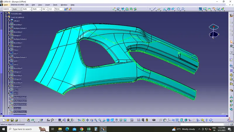
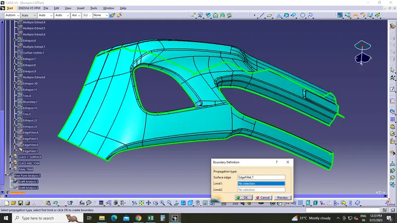
- First offsetted the class A by 3mm(ie, thickness of comp.) to the proper direction.
- Some of the patches were missing in the B surface after the offset.
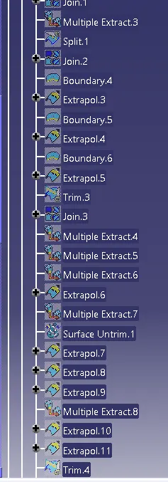
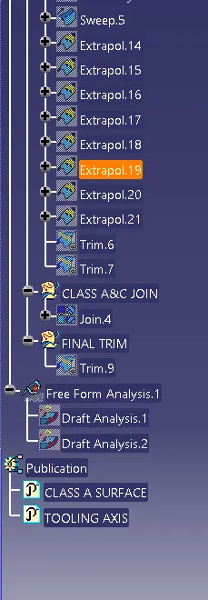
- So i used the Boundary, Extrapolation and Sweep commands to fill the gaps properly and created a complete class B surface.
CREATION OF CLASS C SURFACE
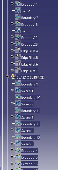
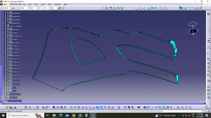
- Using boundary command created separate boundaries on the edges of the class A surface and used the SWEEP command to create class C.
- 3 degree draft were given to the edges which were perpendicular to the tooling axis.
- And no draft were given to the edges parallel to the tooling axis and sweeped those edges normal to the reference surface.
- Edges of all the separately created class c were extrapolated and then trimmed to make it as a single unit.
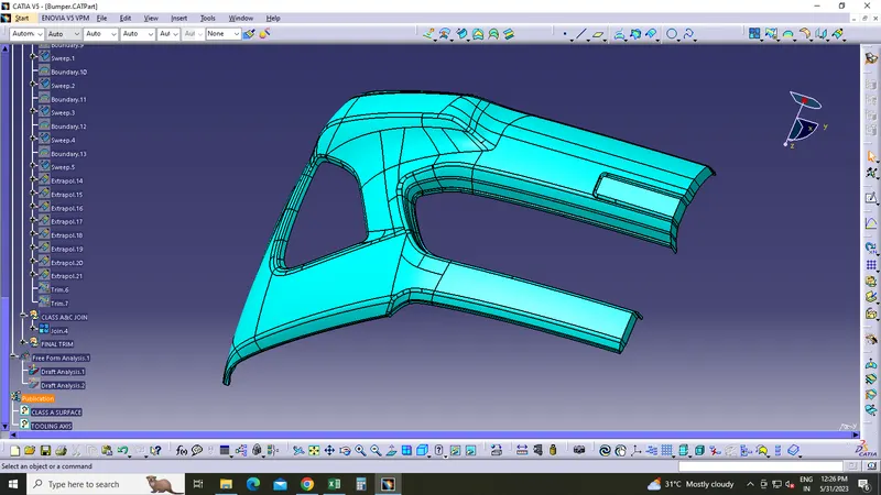
- For the center sweeped c which was not touching any other sweep, used the Join command to join all the C surface together.
- Then joined the class A and class C surafces together.
- After that this class A+C join were trimmed with the class B surface to get a closed component.
- Used the boundary command to check whether the component has any open boundaries or not.
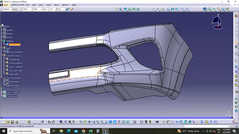
- Then in the part design workbench used the CLOSE SURFACE command to create a solid out of the component.
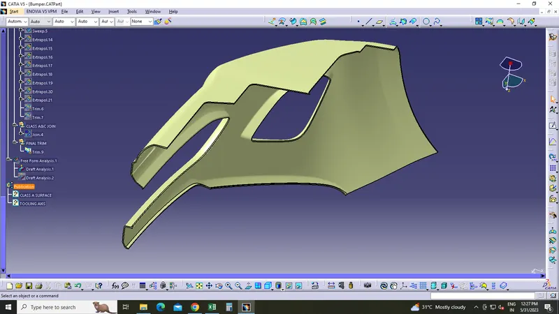
DRAFT ANALYSIS ON FINAL SOLID COMPONENT
- Draft analysis has performed on the final component in the same method which i used for the draft analysis of class A surface.