Week 9 - Challenge 1 - Base Bracket Design
BASE BRACKET DESIGN
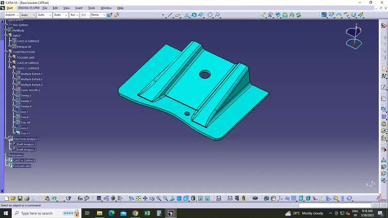
OBJECTIVE: To design the base bracket by working in the given class A surface by creating,
- Tooling axis
- Performing draft analysis
- Creating class B and C surfaces.
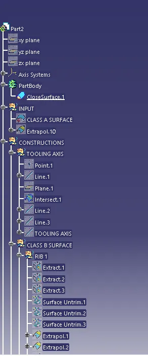
CREATING A TOOLING AXIS
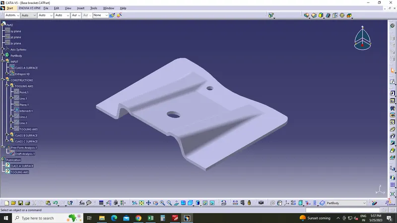
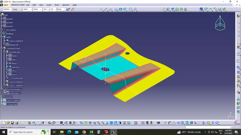
- First i anaysed the part and then created a dummy tooing axis along the z axis through the reference point created.
- The reference point was created in the center of a circle in the flat face of the component.
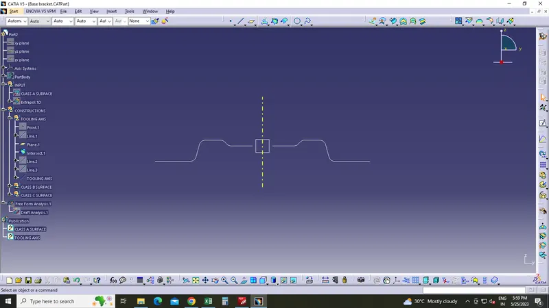
- I intersect the boundary of the component in the yz plane and created 2 lines in the sloped faces.
- created bisecting line to get the final tooling axis.
- Published the tooling axis.
DRAFT ANALYSIS
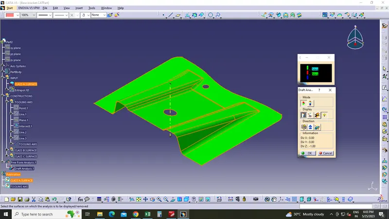
- First i put the part under material mode.
- Insert> Analysis> Feature draft analysis.
- Two windows appeard and one of it shows the colour scale of the draft angle.
- Then i drag the compass and placed it along the tooling axis on it and locked it.
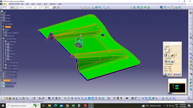
- Clicked on the component so that it turns green and analysed the draft angle in different faces of the component.
- Minimum draft angle is considered as 3 degree.
CREATING CLASS B SURFACE
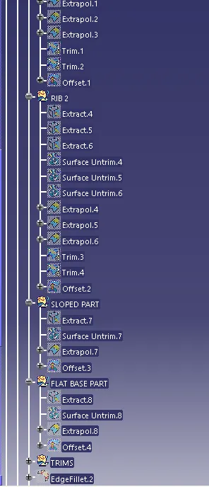
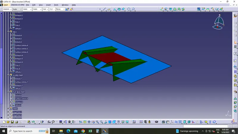
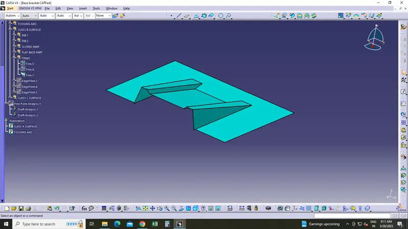
- For creating the class B surface i visualized the component as 4 parts; Rib1,Rib2,Flat face and a Slopped face with hole.
- I performed the following oparations on these parts separately in an orderly manner.
- Extracted the faces excluding fillets.
- untrimmed it.
- Extrapolated each face.
- Trimmed each to shape
- Offseted to given thickness of the component.
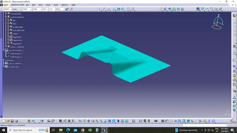
- Trimmed all 4 parts together.
- Finally fillets were given.
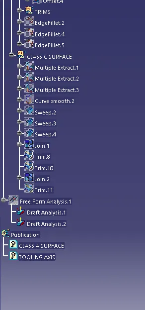
CREATING CLASS C SURFACE
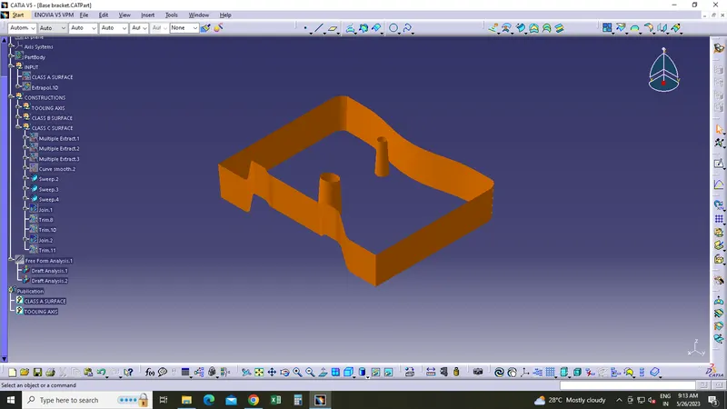
- Class C surface is created using Sweep command.
- Boundary of the class A surface is swept along the tooling direction with 3 degree as angle.
- Then i joined class A and C.
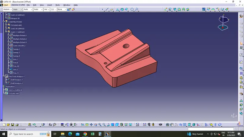
- Trimmed that Join with the class B surface to get the final closed component.
- Then under the partbody used the close surface to make the component solid.