Week 10 - Challenge 1- Attachment Feature Creation (Ribs & Screw Boss)
SWITCH BEZEL DESIGN
OBJECTIVE : Attachment feature creation (Ribs & Screwboss) with creation of class B and C surfaces using the given class A surface, creating tooling axis and performing draft analysis.
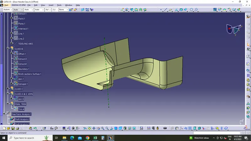
CREATING TOOLING AXIS
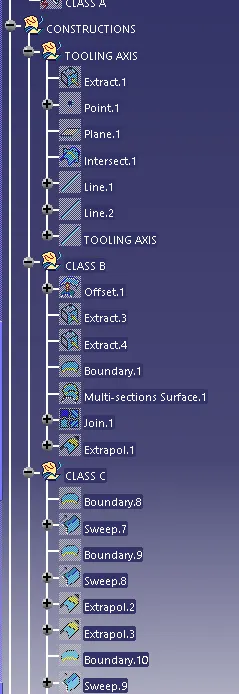
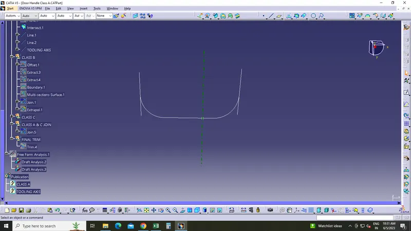
- Tooling axis is created using the bisecting method.
- Extracted the base flat surface of class A and created a reference point.
- Intersected the class A along the xy plane created and drawn 2 lines along the sloped faces.
- Then created a bisecting line for the 2 lines through the reference point and created the tooling axis.
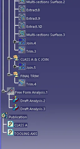
- Published the tooling axis.
DRAFT ANALYSIS ON CLASS A SURFACE
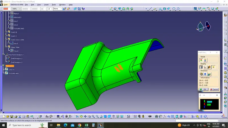
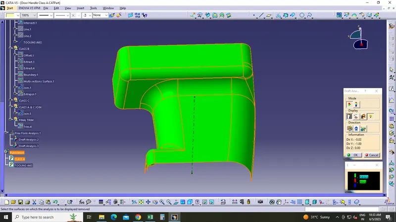
- Changed the view mode to Material mode.
- Insert>Analysis>Feature draft analysis
- Activated the compass and then by dragging the red point, placed the compass along the tooling axis and locked it.
- Clicked on the part and analysed the draft angle of component.
- Considered the min. draft angle as 3 degree.
- The green colour area shows that the component satisfies the given draft angle.
CREATING CLASS B SURFACE
- To create class B surface, the whole class A surface is offseted by 2.5 mm.
- A surface patch was missing, so i used the Multi section surface command to fix it.
- Then I extrapolated the whole class B to a small value.
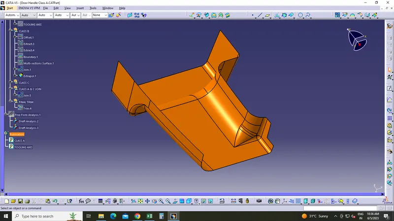
CREATING CLASS C SURFACE
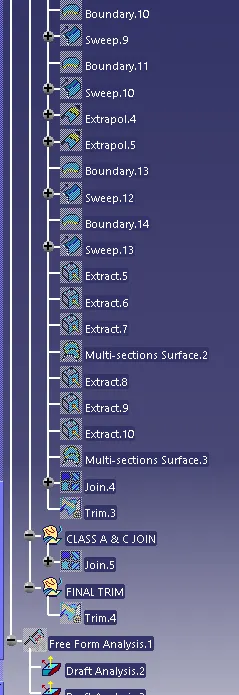
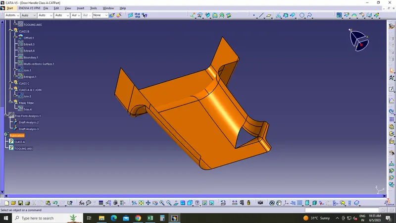
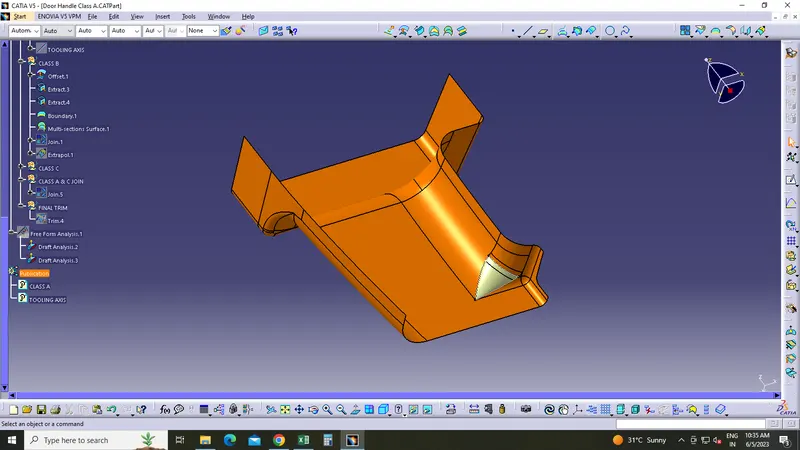
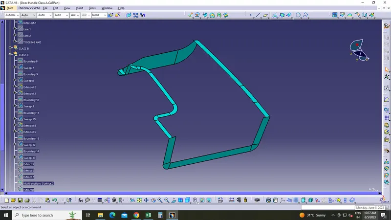
- Using the Boundary, Sweep, Multi section surface commands class C surface is created as different patches.
- Extrapolated the edges to meet the gaps and trimmed to create a single class C surface.
- Joined class A and C together.
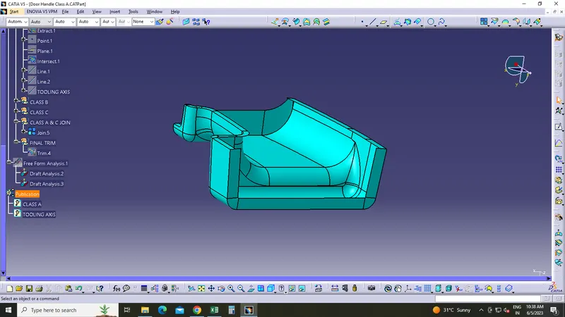
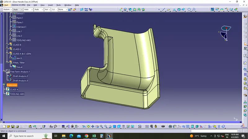
- Then trimmed the join with the class B surface.
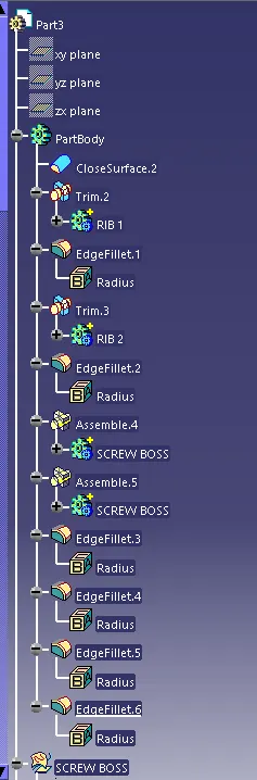
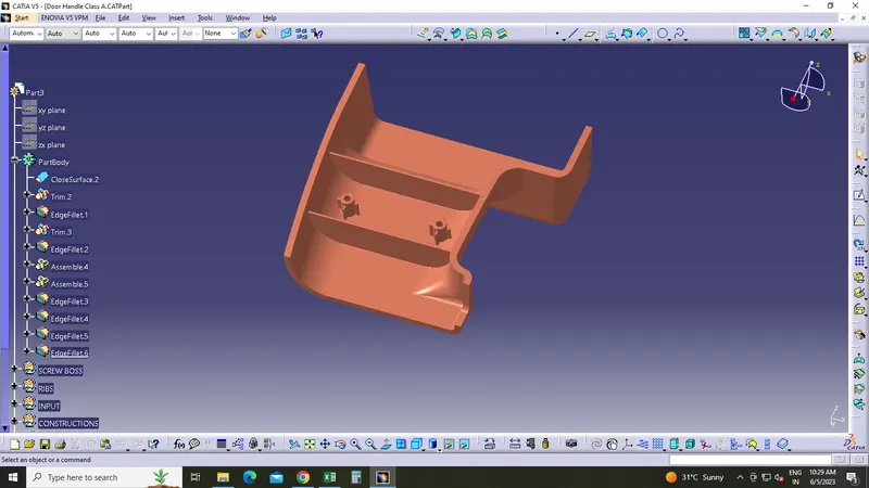
- Finally, under the partbody used the close surface to make the component solid.
CREATING RIBS
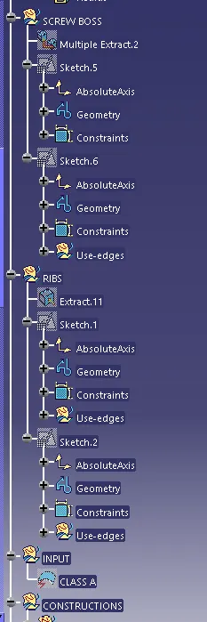
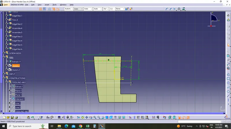
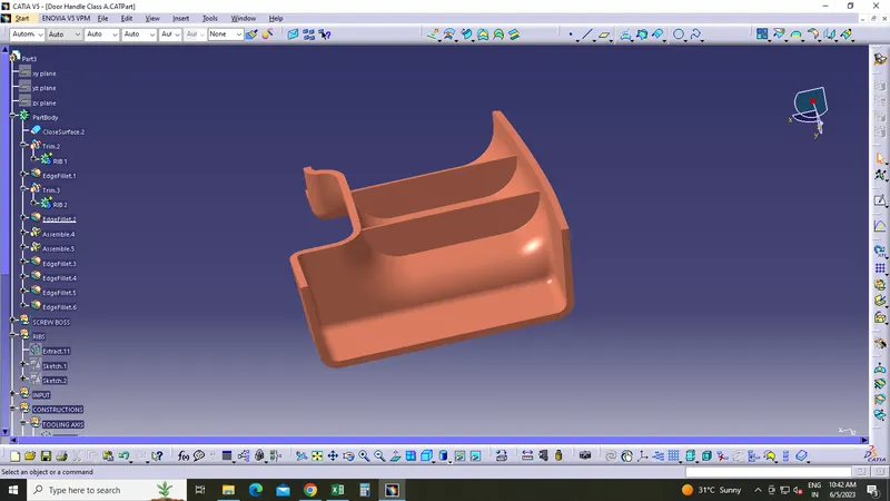
- Ribs are created based on the design rules.
- All the dimensions are taken according to the design considerations.
- Positioned sketches are created and then padded the sketches accordingly.
- After providing the draft, used the boolean operation to add it to main body.
- Then fillets were given.
CREATING SCREW BOSS
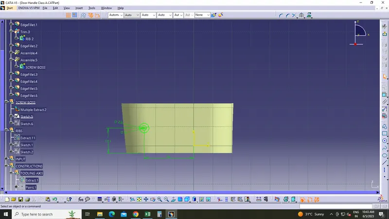
- According to the design considerations given, basic sketches are created.
- Padded the sketch and then draft is provided.
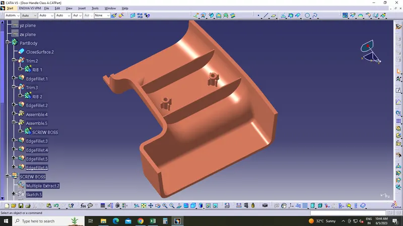
- Using the boolean operation added the screw boss to the main body.
- Fillets were given.
- Using the traslate command created the second screw boss.
DRAFT ANALYSIS ON FINAL SOLID COMPONENT
- Final draft analysis is performed just like the steps explained in the draft analysis of class A surface.