Week 9 - Challenge 2 - Switch Bezel Design
SWITCH BEZEL DESIGN
OBJECTIVE : To design the switch bezel by creating a class B and C surfaces using the given class A surface, creating tooling axis and performing draft analysis.
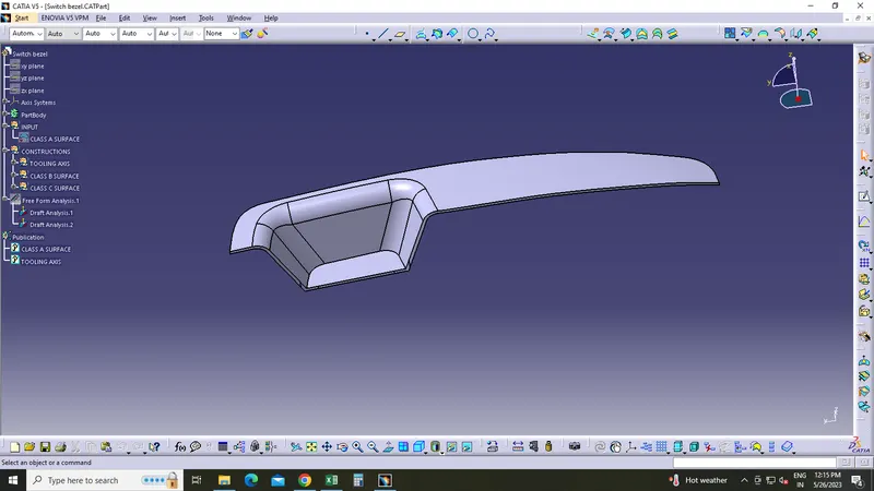
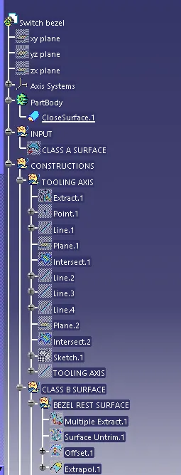
CREATING TOOLING AXIS
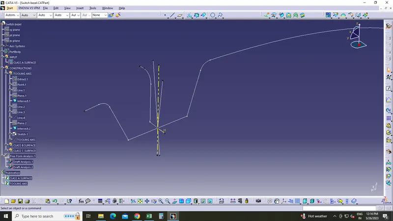
- Tooling axis is created using the bisecting method.
- Extracted the base flat surface of class A and created a reference point in the center.
- Inserted an axis system in the reference point with current feature is disabled.
- Intersected the class A along the yz plane and drawn 2 lines along the sloped faces.
- Then created a bisecting line for the 2 lines through the reference point.
- Intersected the class A along the xz plane, but here there was only one suface line.
- So i draw a line through the reference point with a measurement of 5 degree from the surface line.
- Then i bisected this line with the first created bisecting line and created the final tooling axis.
- Published the tooling axis.
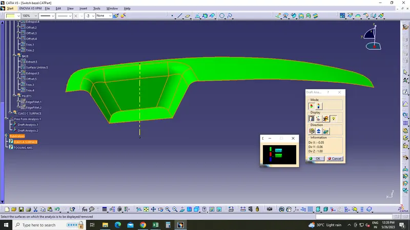
DRAFT ANALYSIS ON CLASS A SURFACE
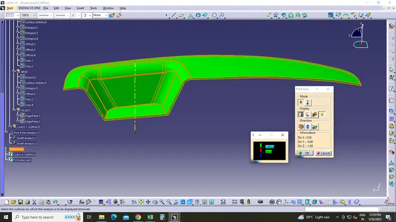
- Changed the view mode to Material mode.
- Insert>Analysis>Feature draft analysis
- Activated the compass and then by dragging the red point, placed the compass along the tooling axis and locked it.
- Clicked on the part and analysed the draft angle of component.
- Considered the min. draft angle as 3 degree.
- The green colour area shows that the component satisfies the given draft angle which was 3 degree.
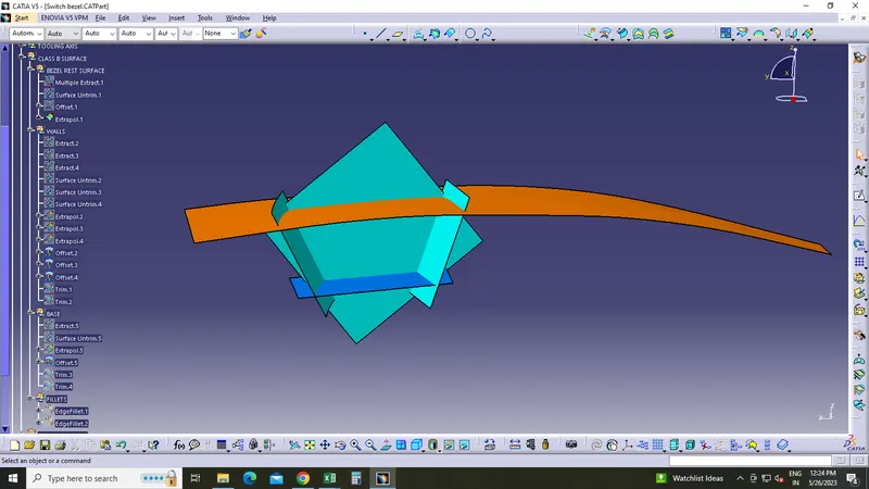
CREATING CLASS B SURFACE
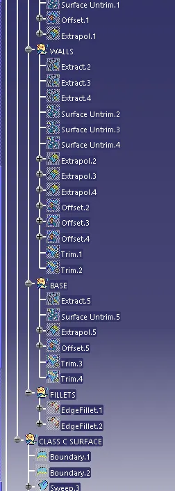
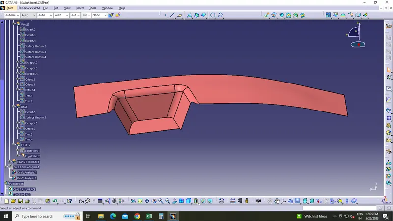
- Extracted the Bezel rest surface, slopped walls and the flat base surface separately under each geometrical set.
- Then untrimmed and extrapolated each surface.
- Offseted the extrapolated surfaces in proper direction to the thickness of the component.
- Trimmed the offseted surfaces together.
- To measure the correct fillet radius, extracted the filleted face from class A and untrimmed it and then measured the fillet radius.
- To ensure uniform thickness, the thickness of the component is decresed from the measured fillet value of class A surface.
- All the fillets were given.
CREATING CLASS C SURFACE
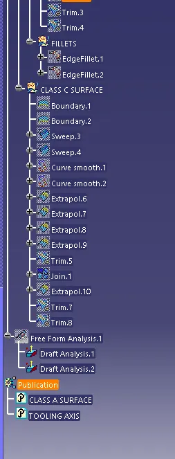
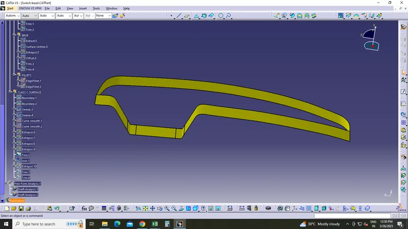
- Using the multiple extract command, the edges of the class A surface were extracted and then converted into smooth curve to avoid patches.
- Sweep operation "with draft direction" is performed by selecting the smooth curve as guide curve and tooling axis as direction and draft angle as 3 degree.
- Used smooth curve command to remove the patches on C surface.Then replaced the corresponding multiple extract with that smooth curve created.
- Extrapolated the edges to meet the gaps and trimmed.
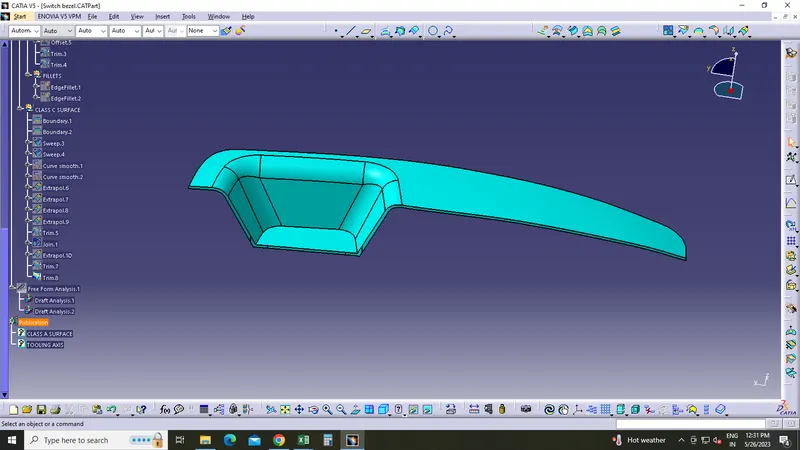
- Joined class A and C together. Then checked if there were any unnecessary boundary present.
- If there were then, I would have increased the merging distance, not more than 0.003mm.
- And even after if there were any unwanted boundary present then, extrapolate class A by a minimal value (eg:0.05mm) and trim it with class C instead of joining them.
- Then trimmed the join with the class B surface.
- Finally, under the partbody used the close surface to make the component solid.
DRAFT ANALYSIS ON FINAL SOLID COMPONENT
- Final draft analysis is performed just like the steps explained in the draft analysis of class A surface.