Week 9 - Challenge 3 - Bumper
--------------------------------------------------------------BUMPER--------------------------------------------------
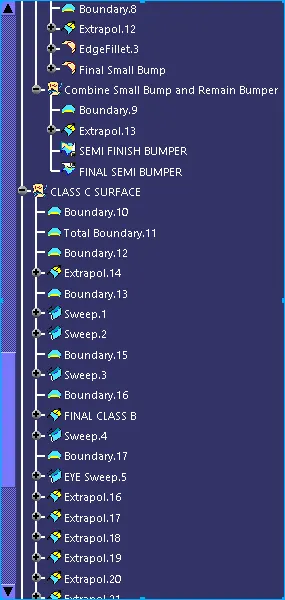
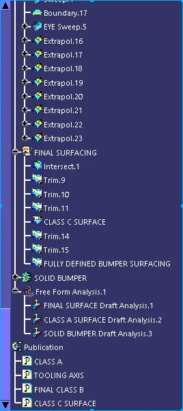
TREE STRUCTURE
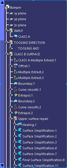
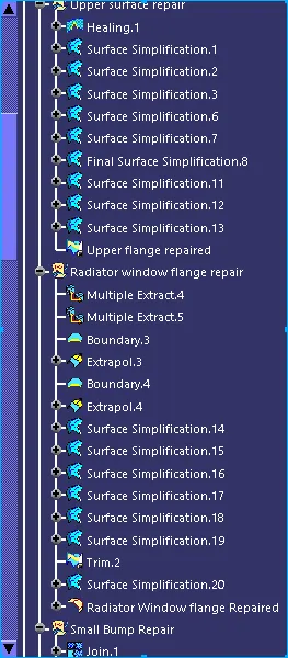
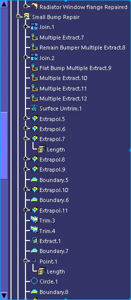
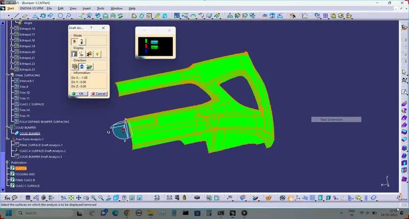
CLASS A SURFACE DRAFT ANALYSIS
FINAL PLASTIC BUMPER DRAFT ANALYSIS
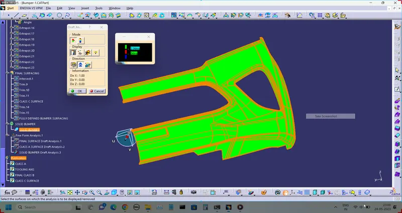
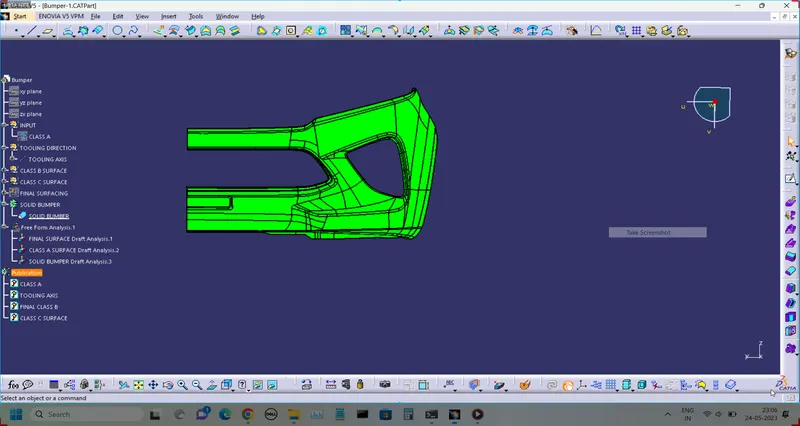
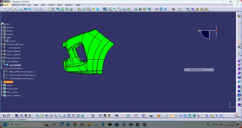
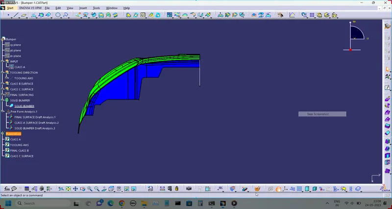
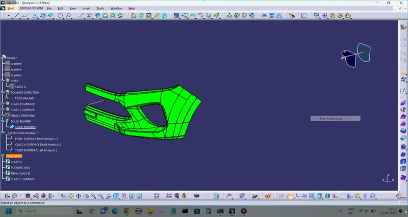
Screenshots of the solid model in various orientations
FRONT VIEW
SIDE VIEW
TOP VIEW
ISOMETRIC VIEW
- REPORT
1. TOOLING AXIS CREATION
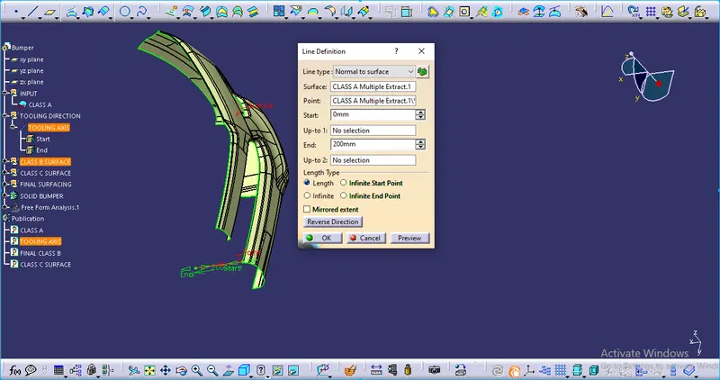
In the bumper surface, there are many curvatures and not any defined shapes by which we can use the Bisection method for defining the tooling axis. So here we will use the Normal to surface line definition.
- Choose line command and Normal to surface option.
- select the midpoint of the bumper and select the Class A surface.
- extend the line and exit from the command.
Now the tooling axis has been created and we will check the direction of the tooling axis by draft analysis.
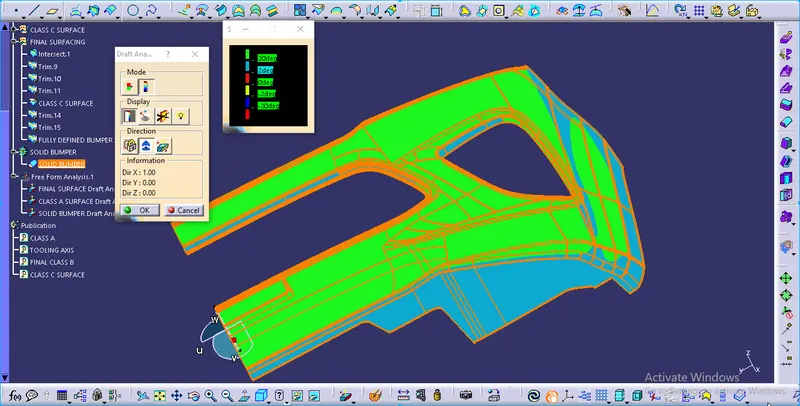
2. Draft analysis
- Select the Feature Draft Analysis
- click the part and define the tooling Direction
- Green Side is showing that the part will be made according to the Draft Angle which is 3 degrees and there will no erosion between the Tool and Plastic parts.
- The blue side is showing a negative Draft angle (interference) or is impossible to draw the part according to the draft angle.
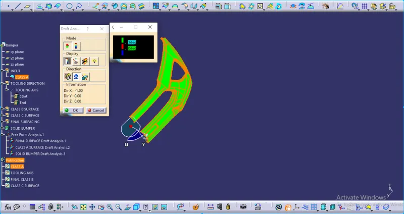
NOTE: OUR TOOLING AXIS IS IN THE PROPER DIRECTION WITH A DRAFT ANGLE OF 3 DEGREES.
TOTAL DRAFT ANALYSIS