Week 9 - Challenge 3 - Bumper
AIM:
To make a model from the provided class-A surface.
INTRODUCTION:
CLASS-A SURFACE:
A surface made by the designer which is given as an input to the plastic modeler to work on. It is aesthetic surface
and the outer most surface.
CLASS-B SURFACE:
A surface below a certain thickness from the class-A surface is class-B surface. This is the surface that contains
engineering aspects of a model.
CLASS-C SURFACE:
A surface that joins class-A and class-B surfaces is class-C surface.
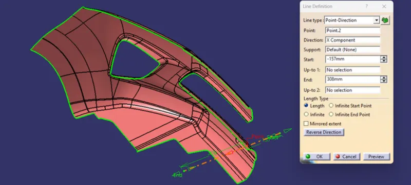
Class A Surface :-
In automotive design application Class A Surfaces are created on all visible exterior surfaces (ex; body panels, bumper, grill, lights etc.) and all visible surfaces of see-touch & feel parts in interior (ex: Dashboard, seats, door pads etc.). This can also include beauty covers in the engine compartment, mud flaps, trunk panels and carpeting. This surface has 0 mm thickness.
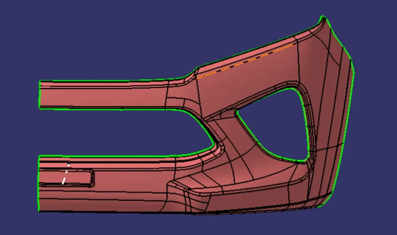
Draft Analysis :-
The Draft Analysis allows the user to easily analyze a part for proper draft angle. A Draft Angle describes the amount of taper for molded or cast parts perpendicular to the parting line. Draft Analysis is applicable for 3D part models. To create a draft analysis for any 3D part file, the user needs to select part/surface select the pull direction. You can change the pull direction.
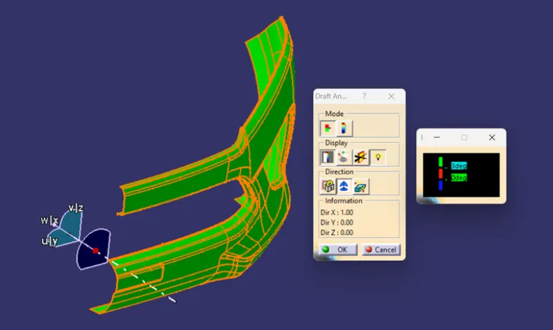
Draft Analysis of Class A Surface In CATIA :-
It provides colour based identification. With the help of this we can easily find that which surface is in clear and which is in stuck by colour changing. Here I give the draft angle 3 degree. The result in colour based that the surface which green is right. And where the colour is blue mean draft angle is 3 degree to 0 degree if this surface area is low then you can go. If you find red colour zone then it means draft angle is less than 0 degree. Then you will have to create tooling axis by another way if possible, otherwise you can say your design engineer to correct for designing.
CREATION OF B-SURFACE :
The A-surface is offsetted by 3.00mm as it is the thickness required.
The Areas where the B-surface has issues are corrected by closing them using commands like Multi section,Sweep,Offset and extract.
Finally all the created surfaces are trimmed or joined together with offset surfaces done earlier. This created a single single surface which will act as the final B-surface.
B surface created is checked for any gaps or errors by creating a complete boundary.
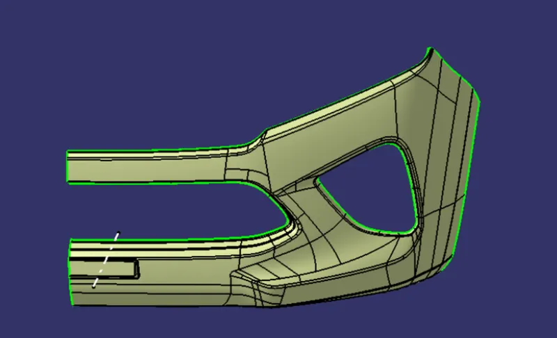
CREATION OF C-SURFACE :-
The A and B surfaces are connected by another single surface which is called the C surface.
It is created by using sweep with A surface acting as the reference surface and curve created from the boundary of the same surface.
Sweep with draft direction is also used to create A-surfaces.
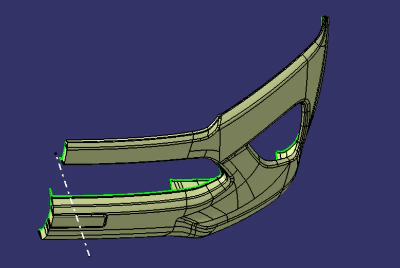
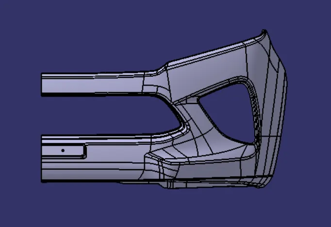
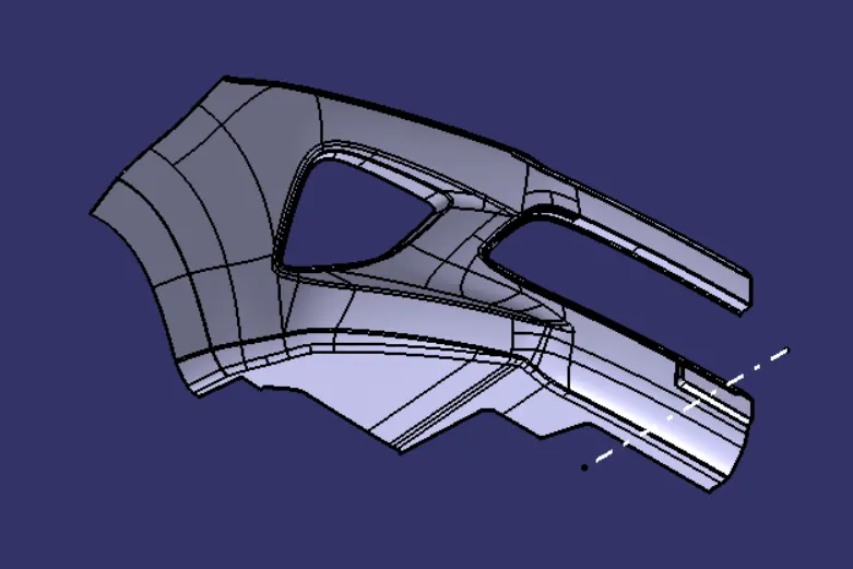
Following is the picture of Class A + Class C surface trimmed together
MODEL TREE:
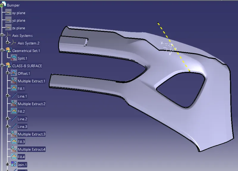
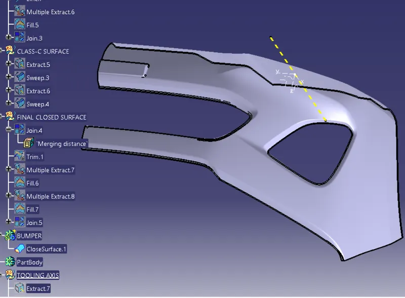
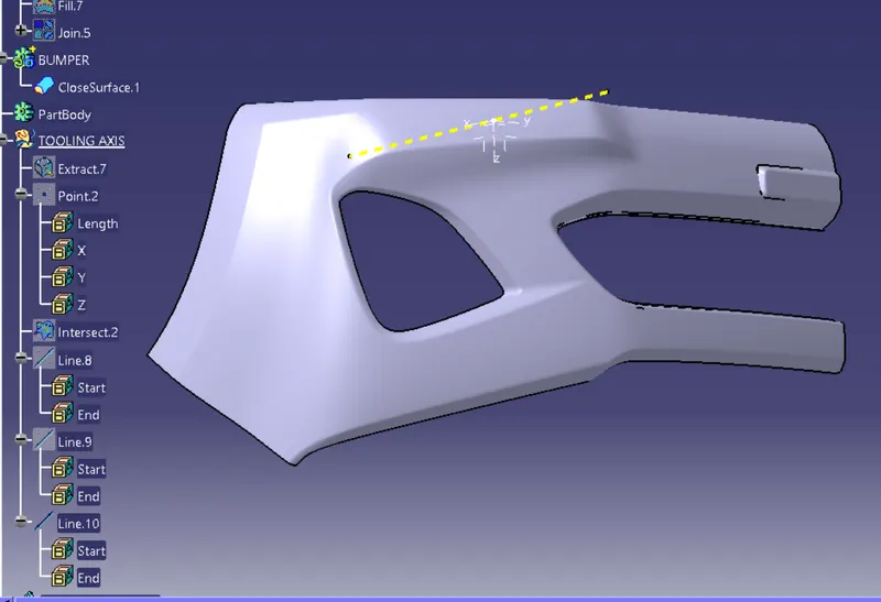
The model tree created shows that all the geometrical sets are named for clarity.
The publications of Tooling axis, surfaces of A,B and C surfaces are done.
Also the closed surface body and Volume is published.
Front View:
Isometric View:
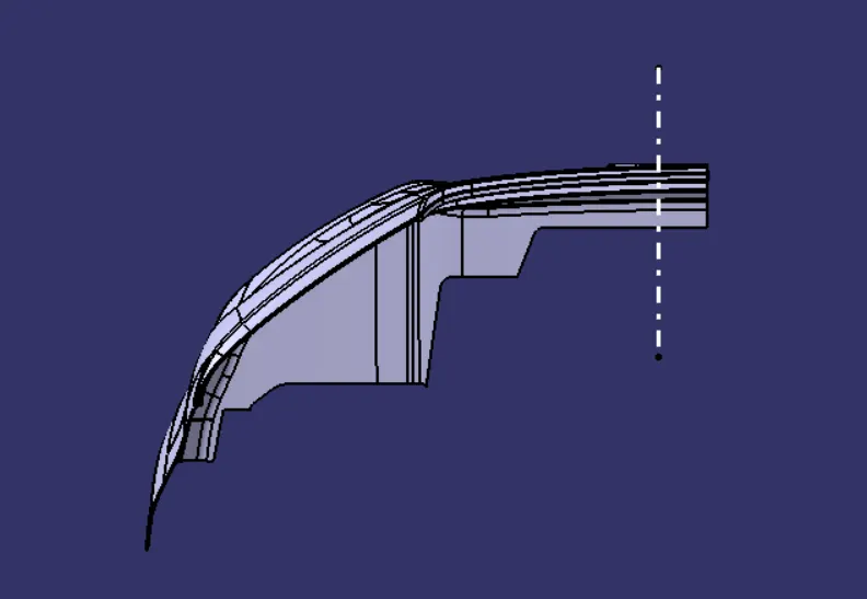
Top View:
Conclusion:
The Draft analysis of the component showed that the component is feasible to be molded without any issues.
Thus it satisfies all design and manufacturing criterias needed for a proper part.
This concludes the report of Design of Bumper Body.