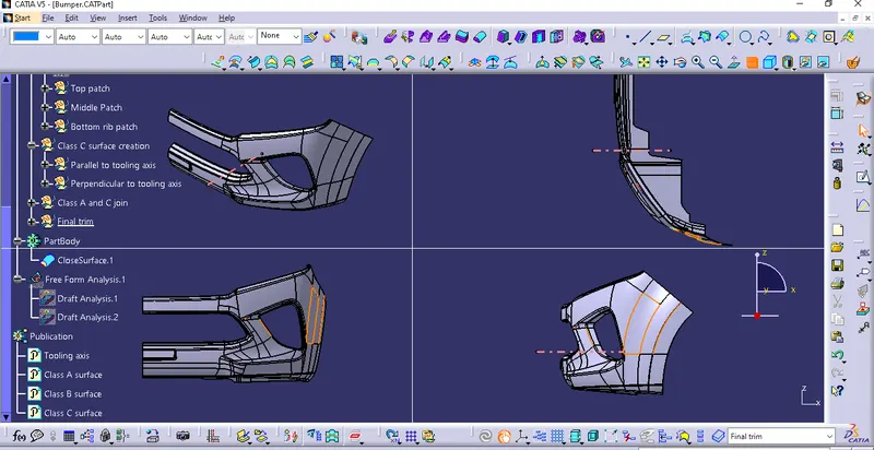
Week 9 - Challenge 3 - Bumper
Tooling axis creation :
- First I find which direction is suitable for creating the tooling axis.
- Then create a dommy tooling axis on a curve to X direction.
- And go to draft analysis to check the dommy tooling axis is clearing the draft direction.
- If it is clearing it should be a main tooling axis.
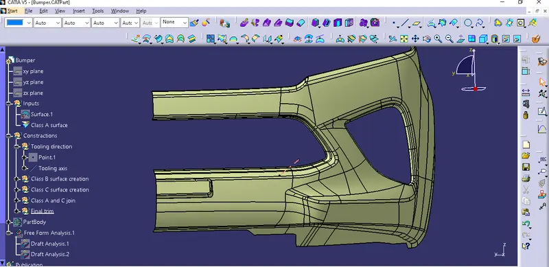
Draft analysis of Class A surface :
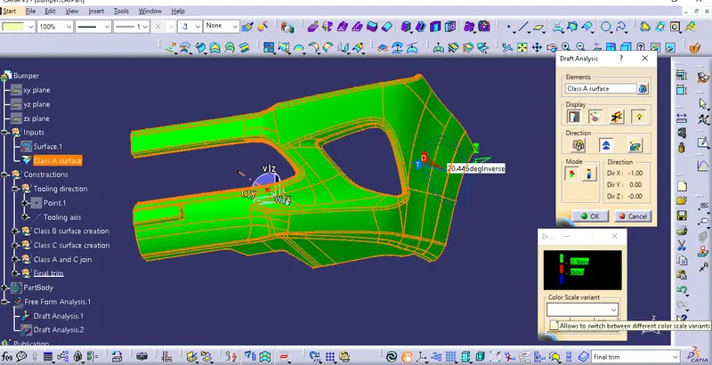
Class B surface creation :
- First to offset the class A surface it shows some open patches on some places.
- Then work on to clear that patches.
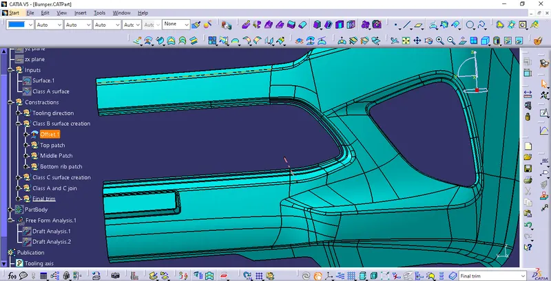
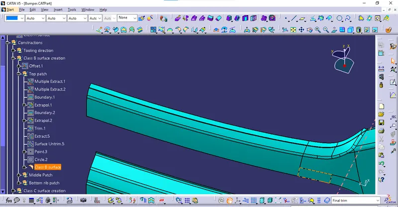
Top patch clearing :
- First I extract the top edge surfaces then extract the remaining all surface by multiple extract.
- Then create a boundary over both surfaces.
- And extrapolate both boundaries to intersect length.
- Then trim them to make a sharp edge.
- Finally measure the edge fillet by extract the fillet and untrim it.
- Then give a fillet value
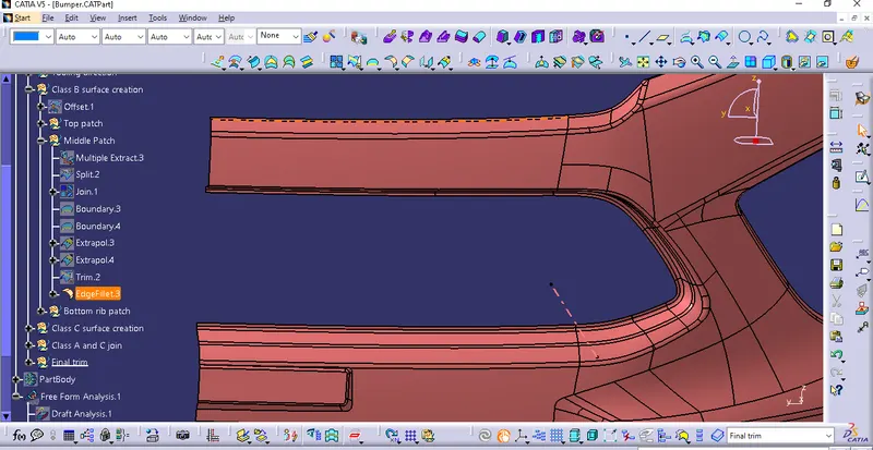
Middle patch clearing :
- First extract the edge bitween the fillet gap and the edge suface.
- Use Split command to split the patch in the surface with the cutting element use that extract.
- Then use the Join command in that sub elements to remove option to remove the patch gap.
- And create the boundary of the split surface and the join surface.
- Extrapolate the boundaries to intersect each other.
- Then trim them to make a sharp edge.
- Finally measure the fillet radius then give it.
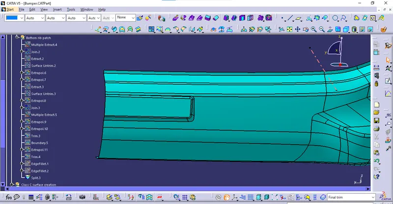
Bottom rib patch clearing :
- First extract the rib surface.
- Then use Join command to remove the whole rib surface.
- Extract the top and side fillet surfaces.
- Some faces are problem to make a extrapolation.
- So extract them separately then untrim them.
- Then go to extrapole the all rib surfaces to intersect them then trim it.
- Create the boundary over the outer rib surface then extrapolate that.
- And trim them then find the fillet values.
- Then give the values to the edges.
- Some unwanted execess surface are there so use the split option with the cutting element as a ZX plane.
Class C surface creation :
- In class C creation some edges are parallel to the tooling axis and some edges are perpendicular to the tooling axis.
- So we create the boundaries separateiy for that.
- Then Sweep to create the C surface where the edges are parallel to the tooling axis then use the sweep with referece surface with 90deg draft, where the edges are perpendicular to the tooling axis then use the sweep with draft direction with 3deg.
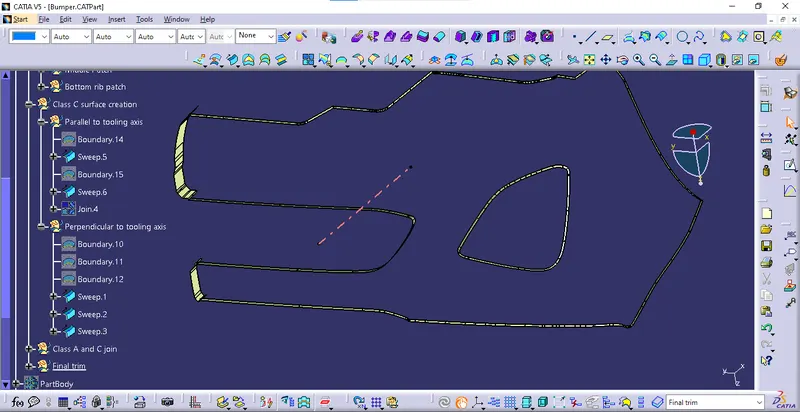
- Once the C surface is created then to trim that sweeps with the surfaces intersecting others.
- And join the C surface to the A surface.
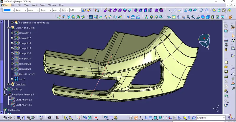
- Once the surfaces are joined then go to the final trim.
- Trim the Class A and C join surface and the B surface.
- If any patch is not intersect then extrapolate it then trim them.
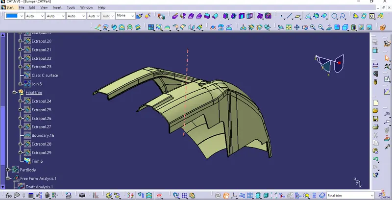
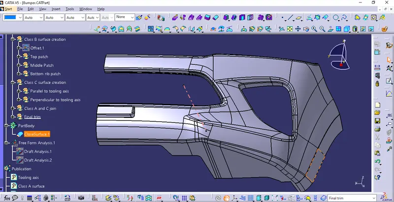
Closed surface part creation :
- The final trim is done ensure any open surface is there with the help of boundary command.
- Then jump in to the Part design.
- And select the closed surface to thicken the surface.
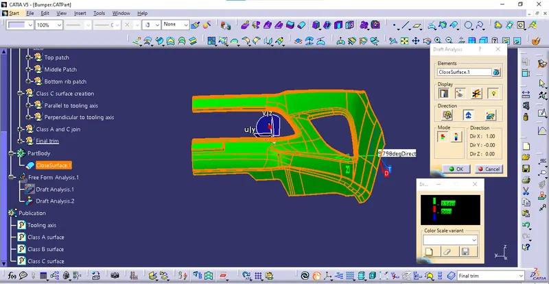
Draft analysis of the final component :
Front view, Top view, Side view and Isometric view :