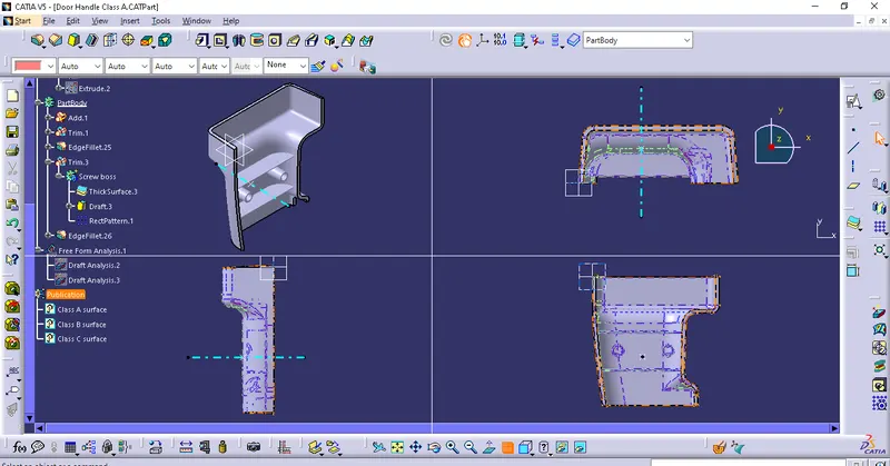
Week 10 - Challenge 1- Attachment Feature Creation (Ribs & Screw Boss)
Tooling axis creation :
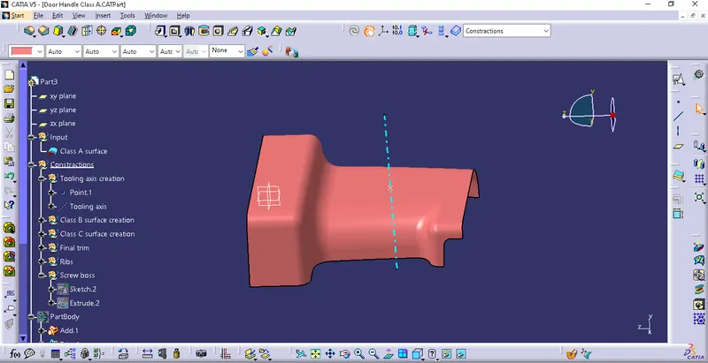
- First I find which direction is suitable to create the tooling axis.
- Y direction is clear the tooling direction so I create the point on a flat surface.
- And create a line by point and direction.
- Then I check the draft analysis to clear the tooing axis is correct.
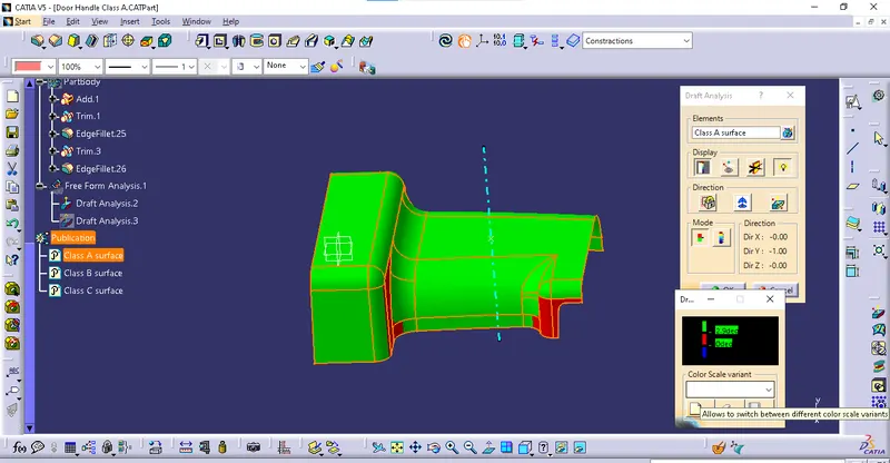
- Select the compass and move that to place on the tooling axis.
- Then click on the Class A surface to see the result.
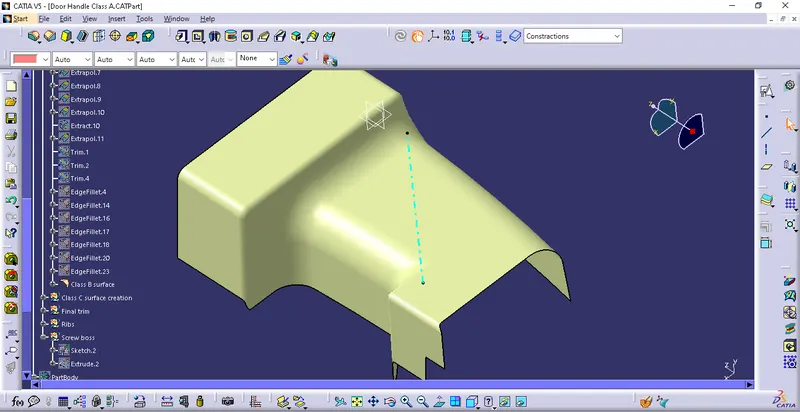
Class B surface creation :
- First offset the Class A surface in 2.5mm.
- Some filleted areas are missing so we create to fill the patches.
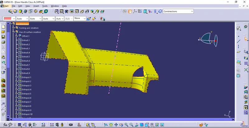
- Exract the all flat faces and make them intersect with each other with the help of Extrapolate tool.
- Then trim them two separately then make a trim of two trim outputs.
- Finally give the fillet values by measuring the offset surface of measure the class A then substract the thickness of the component.
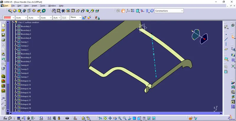
Class C surface creation :
- First I create the boundary of Class A surface.
- Create boundary for which surface is perpandicular to the tooling axis the create the boundary for which surface parallel to the tooling axis.
- Then use the sweep command for the parallel surface to the tooling axis with 3 degree draft by draft with tooling direction.
- Similarly perpandicular surface to the tooling axis with 90 degree draft.
- And make them intersect with each other by Extrapolation.
- Then do the trim to get a Class C surface.
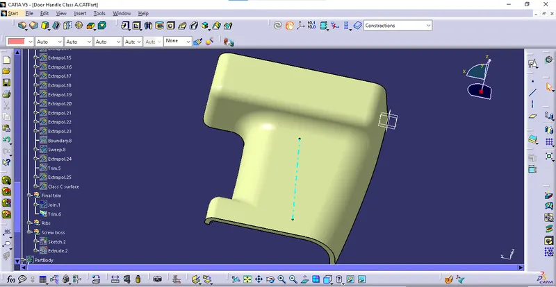
Final trim :
- In this step first join the Class C and Class A surfaces.
- And make a final trim to trim the joined surface and Class B surface.
- We will get the closed suface.
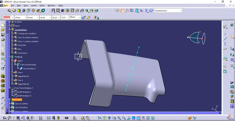
Closed solid part creation :
- Insert a new body and go to the part design.
- Click the closed suface option the select the surface it will make a solid component.
Rib creation :
- Insert a new geometricalset and create a line, give a aproximate value no problem when the line is excess.
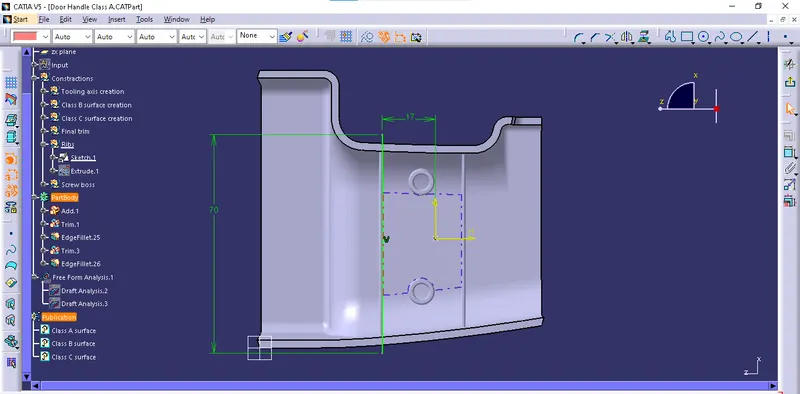
- Then extrude the line of rib hight is 12.5mm and ensure the 1mm of rib is inside the component.
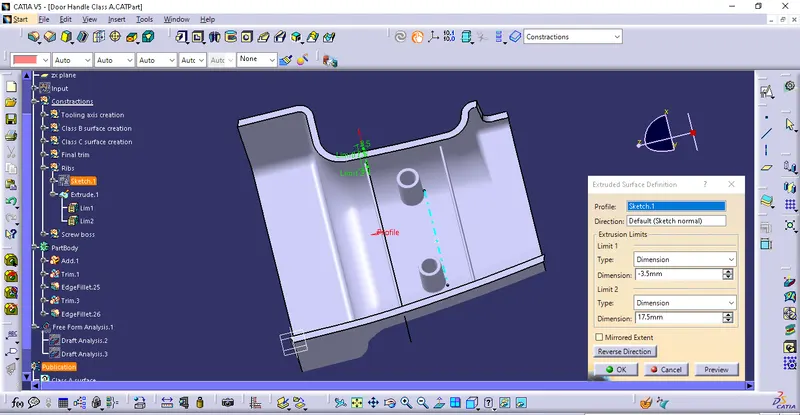
- And I use the thicken surface to make a 1mm rib because 0.4*2.5=1.
- Then translate the rib other side with required value.
- And draft the 4 sides 0.5mm of the each rib and give the neutral surface is bottom face and give the pulling direction as tooling axis.
- Define the partbody then add the final component in it.
- Then union trim the rib to the partbody remove the unwanted faces.
- Finally give the fillet to the ribs 0.25mm.
Screw boss creation :
- Insert the new geometricalset to create the new sketch for screw boss.
- I create the inner dia of the screw boss of 5.2mm.
- Then extrude the circle in 12.5mm.
- And thicken the surface outside 1.5mm because 0.6*2.5=1.5mm.
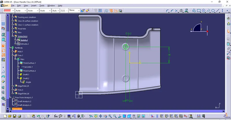
- Then do draft 0.5mm on inside and outside, select the neutral surface as a bottom surface and pulling direction is tooling axis.
- And pattern that at 35mm distance.
- Union trim the screw boss to the partbody.
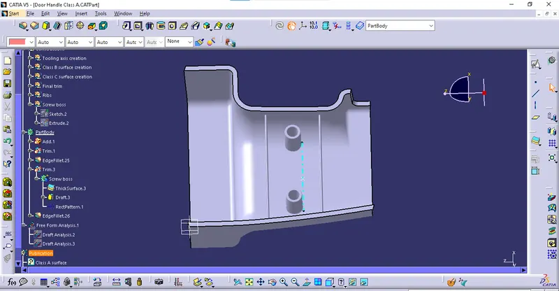
Draft analysis of final component :
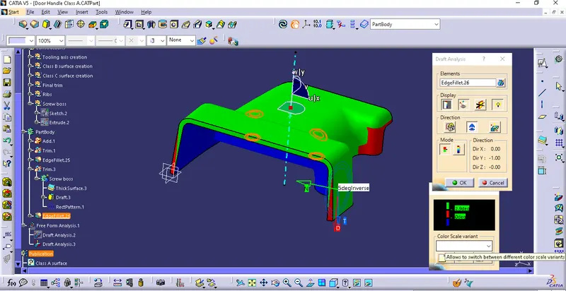
- Click the draft analysis and put the compass on the tooling axis then click on the component.
- The final part is clear the draft analysis.
Front, side, top and isometric view of the component: