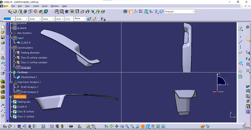
Week 9 - Challenge 2 - Switch Bezel Design
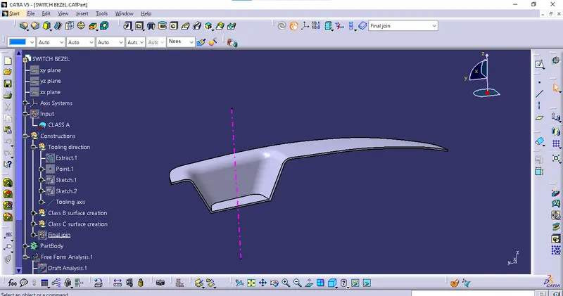
Tooling axis creation :
- Consider which surface is suitable for tooling. I choose Z direction for create the tooling axis.
- Extract the base surface then create the point on that surface.
- Then create the axis system on that point.
- And draw the line on a 3d intersecting parallel lines in x direction then create a bisecting line using those lines.
- Similarly create the line in Y direction.
- And create the bisecting line using the x and y direction lines.
- That is our Tooling axis.
Class B surface creation :
- First I extract the top surface then untrim that and offset at 2.5mm.
- Then extract the wall surfaces then untrim them.
- And extrapolate them to each faces are toch properly.
- Then offset the extrapolated surfaces then trim them.
- And extract the base surface then untrim it.
- Then extrapolate that and offset it.
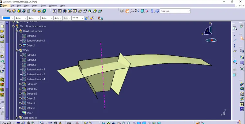
- Then trim the all faces.
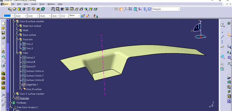
- Then find the fillet radius by extract the filleted face then untrim them.
- And use the vernier caliper to measure the radius and put the value to fillets.
Class C surface creation :
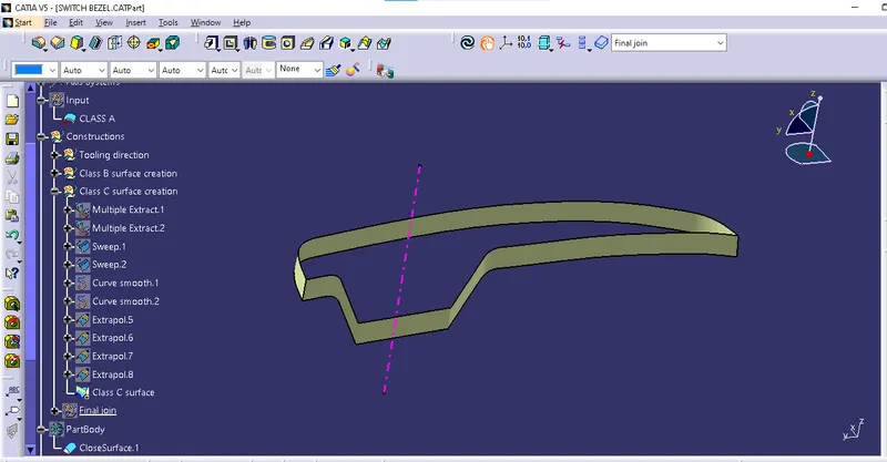
- First extract the boundary or edge by multiple extract with separate patches.
- Then use the sweep command to create the sweep surface.
- The patches are occure in the sweep surface so use the smooth curve.
- If any gap between sweeps then extrapolate the sweep at minimum value.
- Then join the Class A and Class c with join command.
- Finally trim the all surfaces.
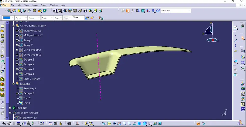
Closed body creation :
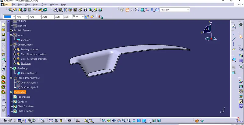
- Then jump into the part design to make a closed solid component.
- Publish the Tooling axis, Class A surface, Class B surface and Class C surface.
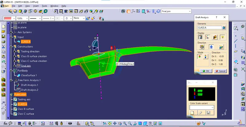
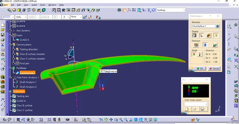
Draft analysis of Class A surface :
Draft analysis of end part :
Front view, Top view, Side view and Isometric view :