Week 9 - Challenge 3 - Bumper
We have to Create the Bumper Plastic component through the given Class-A surface. To begin with, the tooling axis for the given Class-A Surface should be created meeting the requirements of the draft angle and at the end perform the Draft analysis on the model.
Take the Thickness of the component to be 3 mm
Introduction:
CLASS-A SURFACE: the class-A surface is used in the automotive design industry. it describes the final production surface data for the aesthetic parts.
CLASS-B SURFACE: the class-B surface is the second surface that has a specific thickness from the class-A surface. this surface contains engineering aspects of a model. These must also be smooth and "error-free" but are not held to the standards that class A surfaces are.
CLASS-C SURFACE: The Class C finish allows more imperfections than Class A or B. Class C is often specified for interior surfaces not readily visible, surfaces that will be covered by another part when assembled, or surfaces.
Design methodology:
Insert the class A surface of the Bumper in CATIA software.
Determining the tooling axis for the Bumper
Draft analysis of Class- A
Creation of class B surface.
Creation of class c surface.
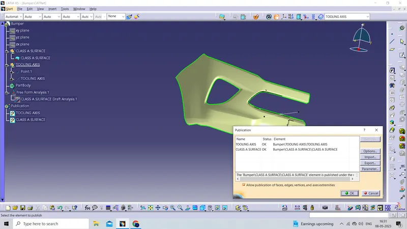
Use the publication option and publish the below
- Tooling Axis
- Class A, B, and C surface
Join the bumper class A, class B, and class c surfaces and ensure all the surfaces are closed.
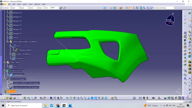
Use the Close Surface feature to make a solid body from the surface.
finally, Perform the Draft analysis on the bumper plastic component.
Creation of Tolling axis:
To create the tooling axis first, we have to check the best suitable direction for tooling by using the compass. the x direction is suitable for creating the tolling axis because, in the x direction, most of the surfaces are clearing while performing draft analysis. Generally tooling axis is created using bisecting line method but here A line normal to the surface is created in the x direction and considered the tooling axis.
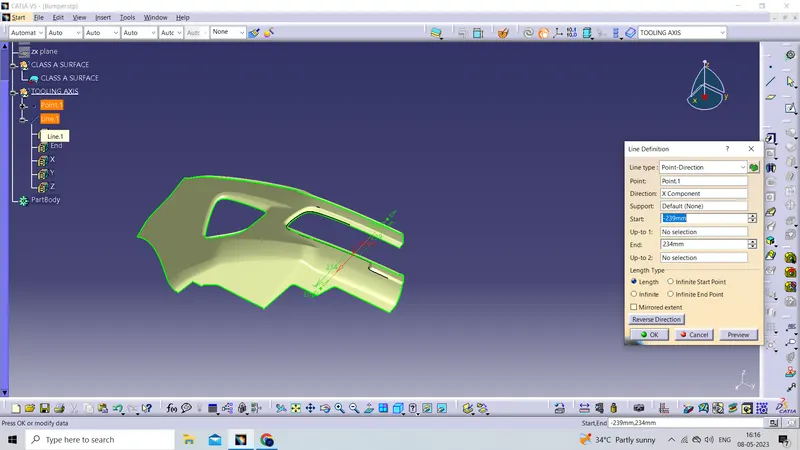
For checking whether our tooling axis is correct or not simply put the created tooling axis in normal view mode if our axis is correct then all the surfaces are visible
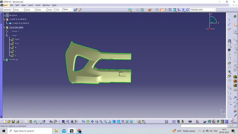
Draft analysis of Class- A
After creating a tooling axis we do the draft analysis. Before drafting we have to make sure that in the view mode, it is selected for the materials.
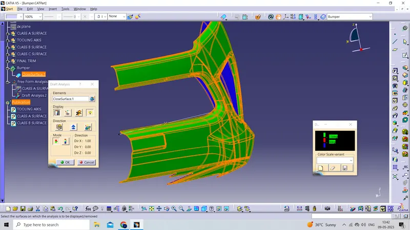
After selecting the feature draft analysis tool we drag the compass from its position to the tool axis. Then lock the compass. After that select anywhere on the component and it will give you the result.
We change the minimum draft for the component to 3°.
We can use the running point option to check the angle of the component.
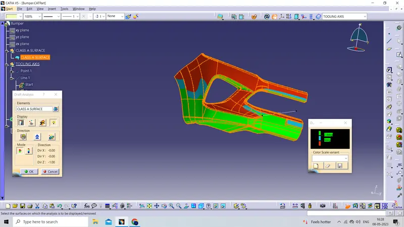
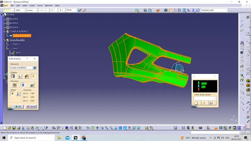
NOW PUBLISHING THE CLASS A SURFACE AND TOOLING AXIS
------------------------------------------------------------------------------------------------------------------------------------------------------------------------------------------------------------------------------------------------------------------------------------------------------------------------------------------------------------------------------------------------------------------------------------------------------------------------------------------------------------------------------
CREATION OF CLASS B SURFACE:
From this challenge we are going with the direct offset method because in previous challenges we can able to see the surface geometry is very easy to create now we will be having complex geometry in our hands so the direct offset method we going to use here
select the offset command-click on CLASS A SURFACE enter the offset value 3mm
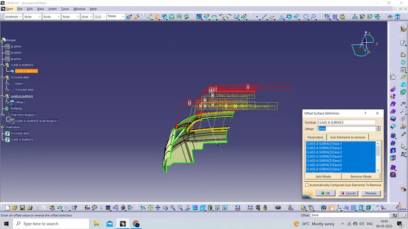
After offsetting we miss some fillet patches we have to retract the missing patch from the offset surface. for that, we use multiple extract commands on another side from the missing patches and then extrapolate them And then trim and then fillet them
Filling the patches on the upper side of the surface by using the following steps
Multiple Extract 1
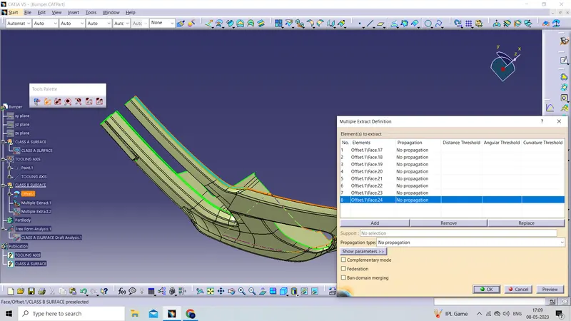
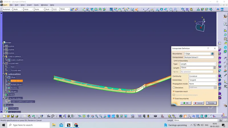
Extrapolate Multiple Extract 1
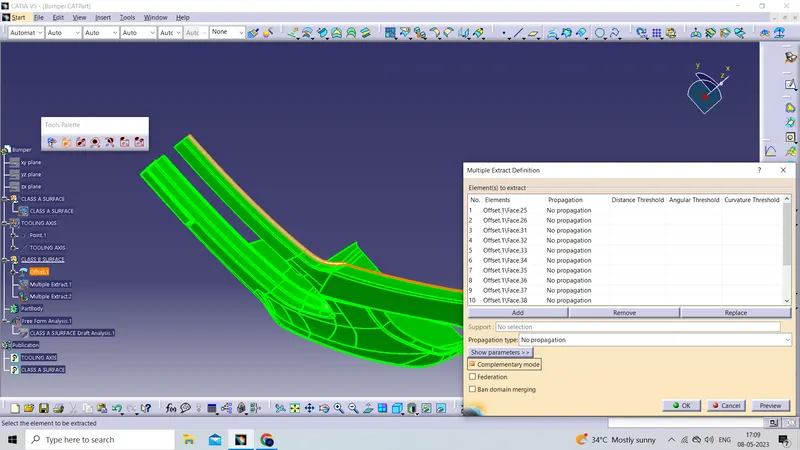
Multiple Extract 2
Extrapolate Multiple Extract 2
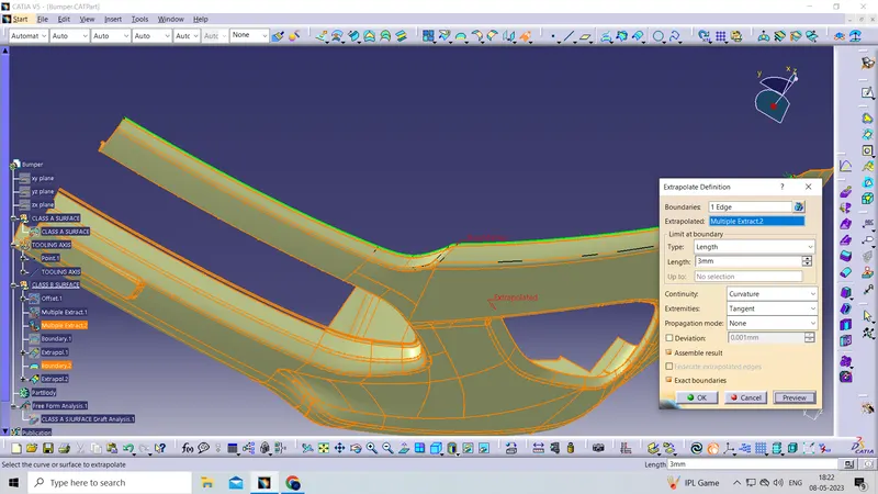
Now check Extrapolate of Multiple Extract 1 And Extrapolate of Multiple Extract 2 are intersecting or not if it is intersecting then trim them together
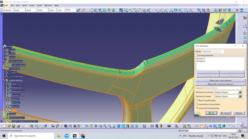
Now Filling the patches on the middle side of the surface by using the following steps
split the patches
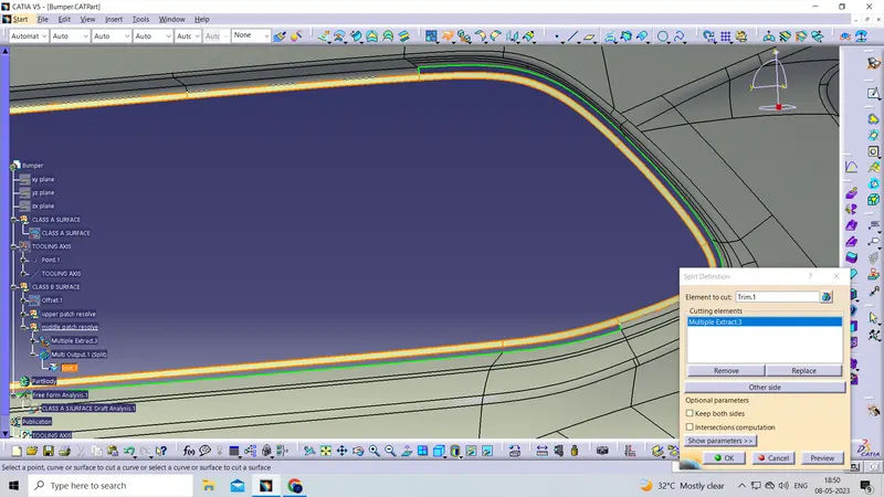
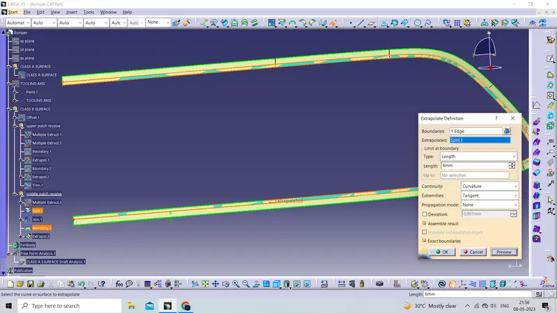
Now give the boundary to the split And then Extrapolate it
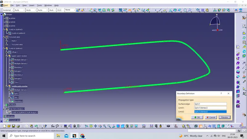
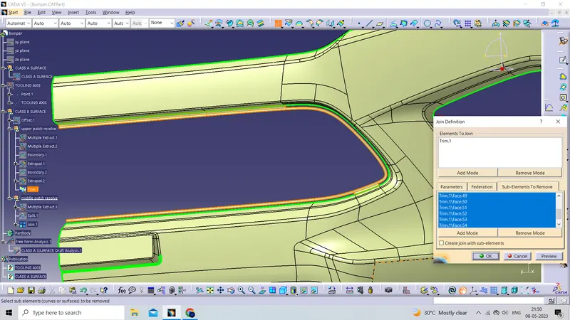
Now use the join>>Sub-element to remove command to remove the patches
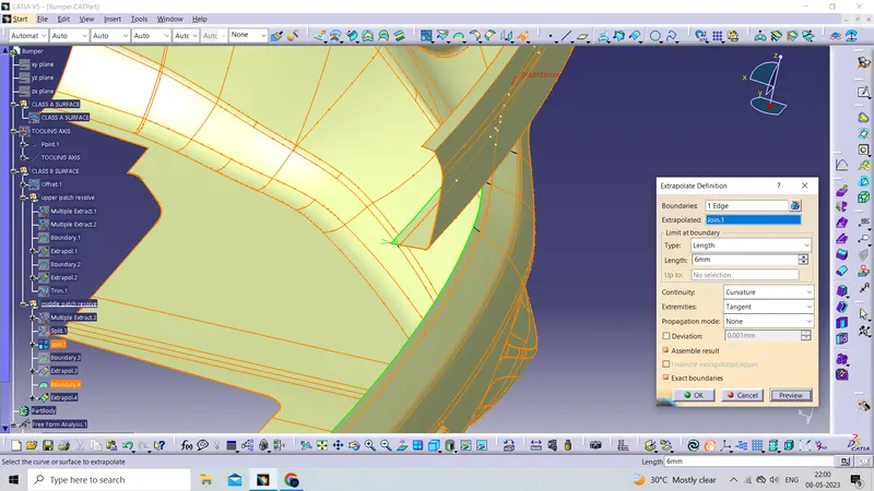
Now give the boundary to the Join And then Extrapolate it
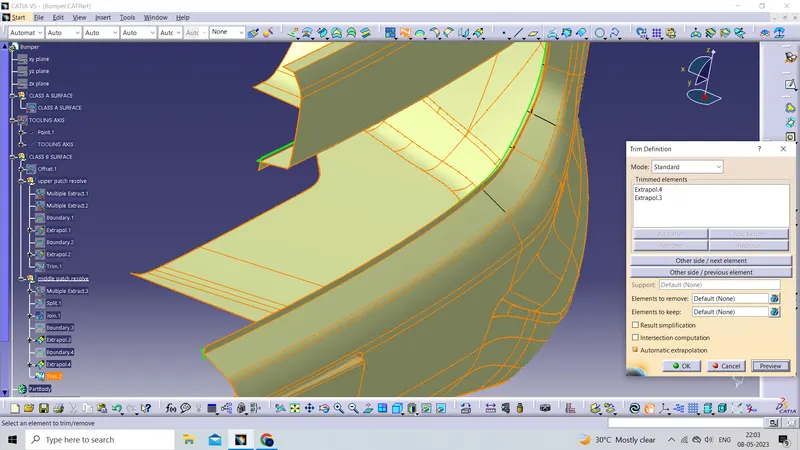
Now trim the extrapolate join And split
Now Filling the patches on the lower side of the surface by using the following steps
multiple extracts 4
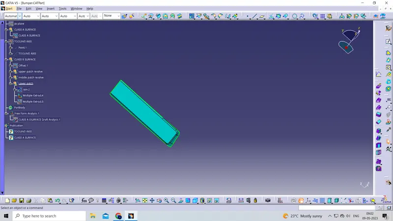
now extrapolate it
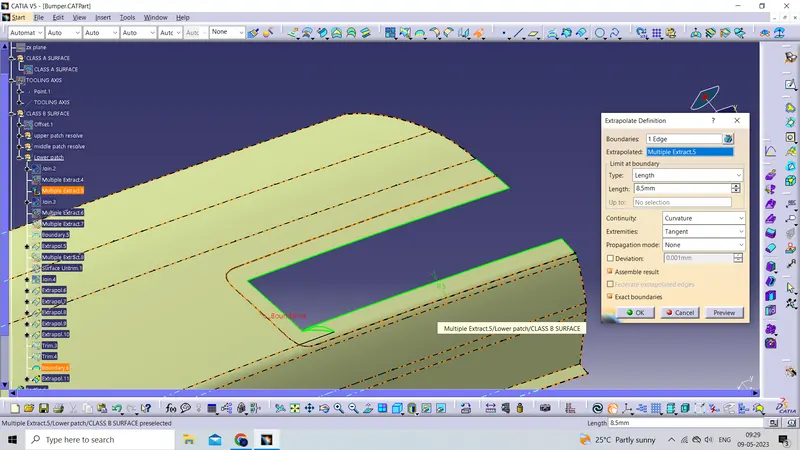
multiple extracts 5
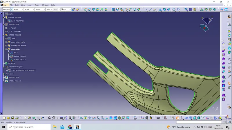
now extrapolate it
Now trim ab above extrapolated surfaces
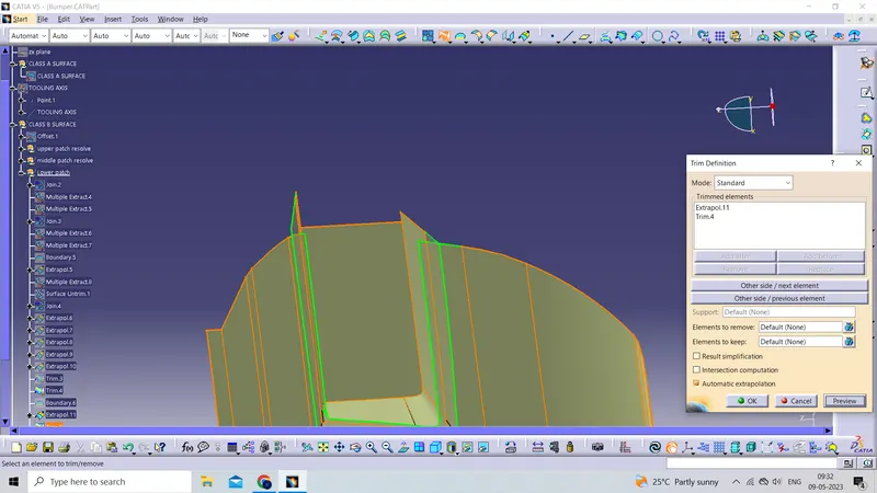
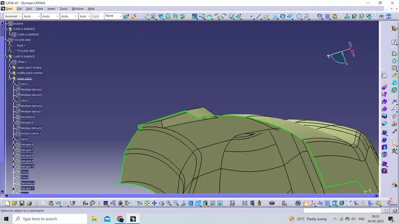
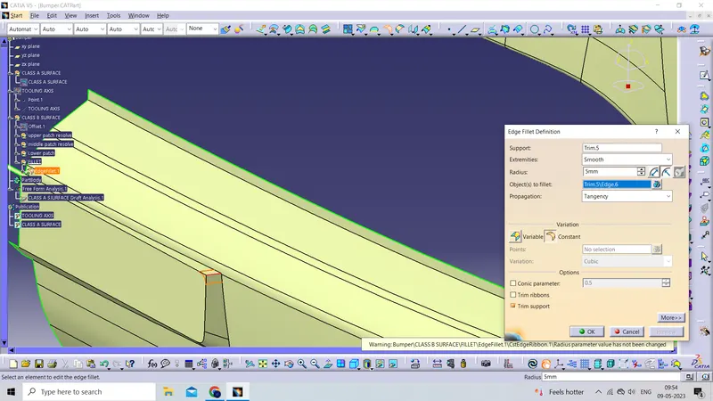
Now filleting the by using edge fillet command
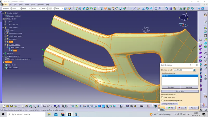
AFTER FILLET split the extra surface from the CLASS B SURFACE
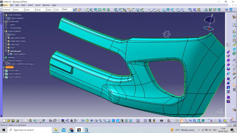
And for a better view change the color of the CLASS B SURFACE
------------------------------------------------------------------------------------------------------------------------------------------------------------------------------------------------------------------------------------------------------------------------------------------------------------------------------------------------------------------------------------------------------------------------------------------------------------------------------------------------------------------------------
CREATION OF CLASS C SURFACE:
We first extract the edges from the Class A surface with the help of the multi extract or boundary command which we create the path for a sweep for class C
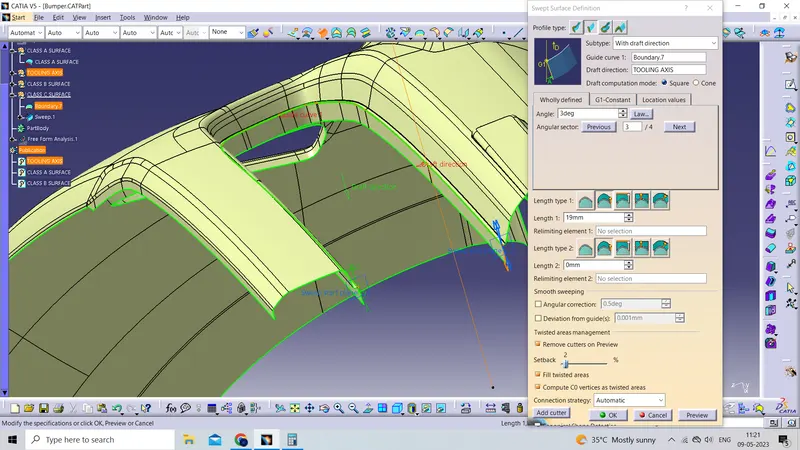
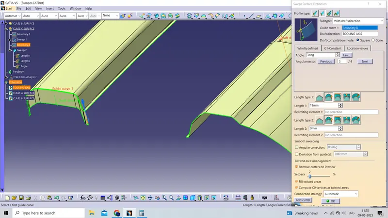
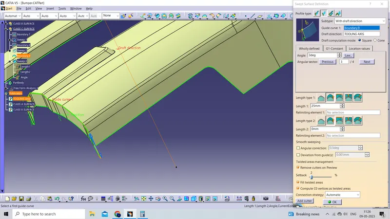
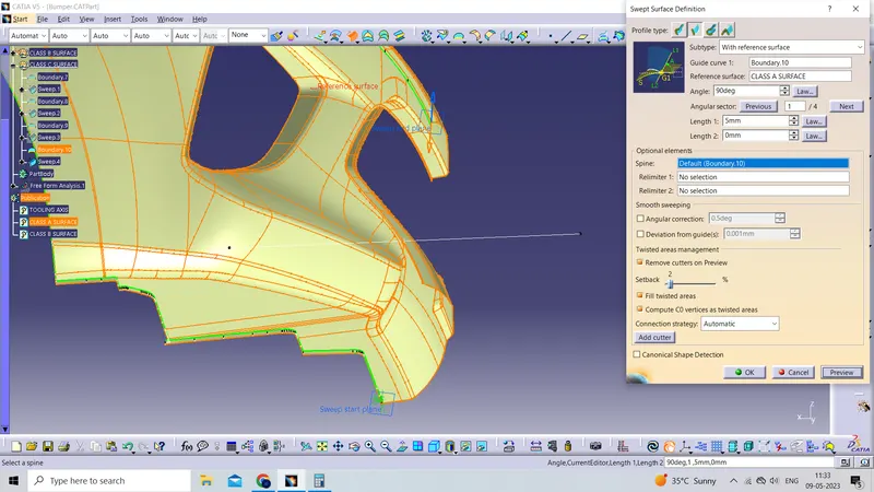
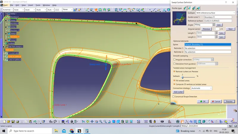
like this, we have to create all separate sweeps and join them together. once all the sweeps are joined together we created a class c surface.
CLASS C SURFACE:
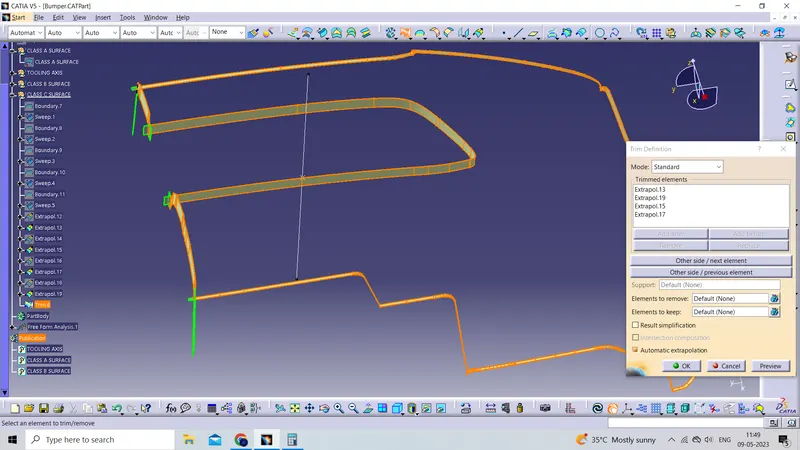
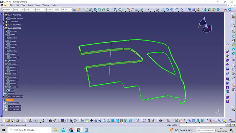
Joining class A surface and class c surface together
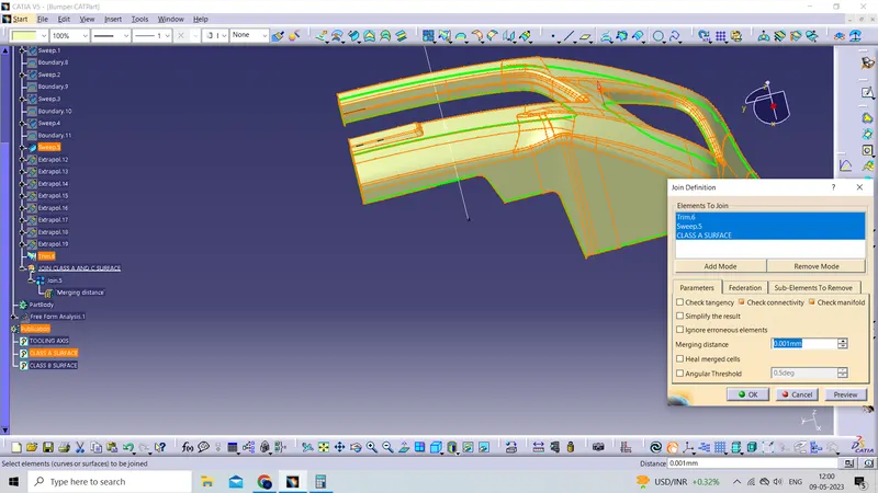
FINAL TRIM
Trim the class-B surface to join (A+C) this will make sure that we get a closed surface. We can check it using the boundary tool, if it gives an error that means that the component is closed.
Then We go to the part design workbench and use to closed surface tool to create a solid body.
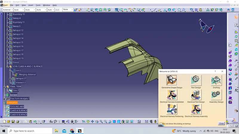
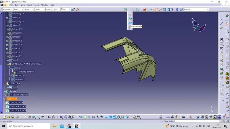
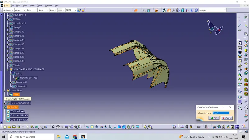
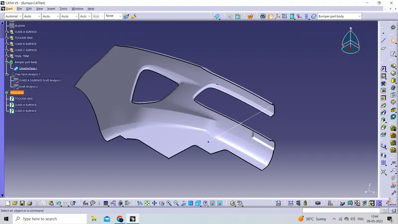
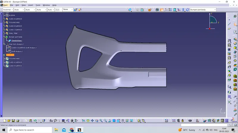
hence, we created our final plastic component.
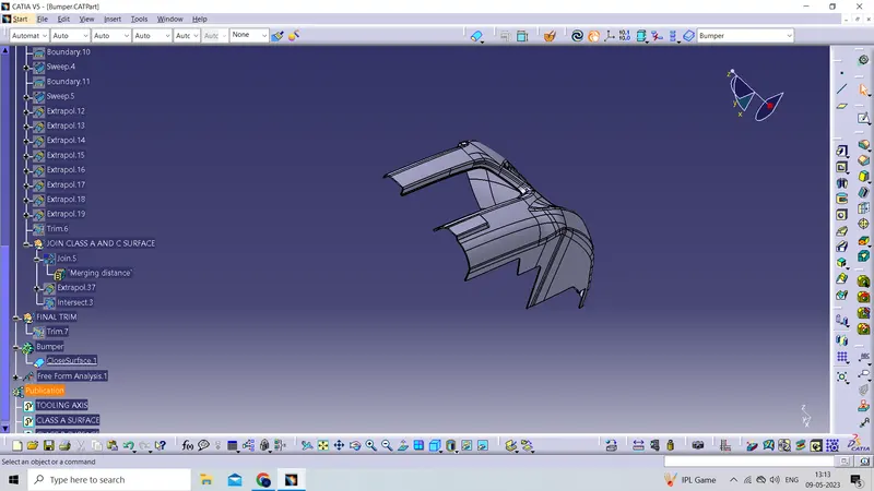
------------------------------------------------------------------------------------------------------------------------------------------------------------------------------------------------------------------------------------------------------------------------------------------------------------------------------------------------------------------------------------------------------------------------------------------------------------------------------------------------------------------------------
Draft analysis of the final plastic component:
- Go to the Insert menu and select the Analysis option.
- Select Feature Draft Analysis.
- Select the Material option and select the surface.
- Drag the compass and place it on the tooling axis.
- click on the surface and see that the surface is within the permissible limit of the draft values.
- Click on Okay.
------------------------------------------------------------------------------------------------------------------------------------------------------------------------------------------------------------------------------------------------------------------------------------------------------------------------------------------------------------------------------------------------------------------------------------------------------------------------------------------------------------------------------
ISOMETRIC VIEW
FRONT VIEW
SIDE VIEW
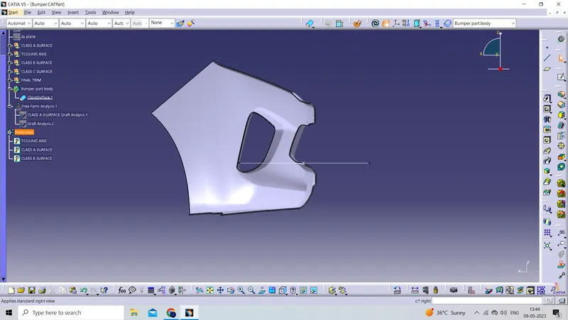
TOP VIEW
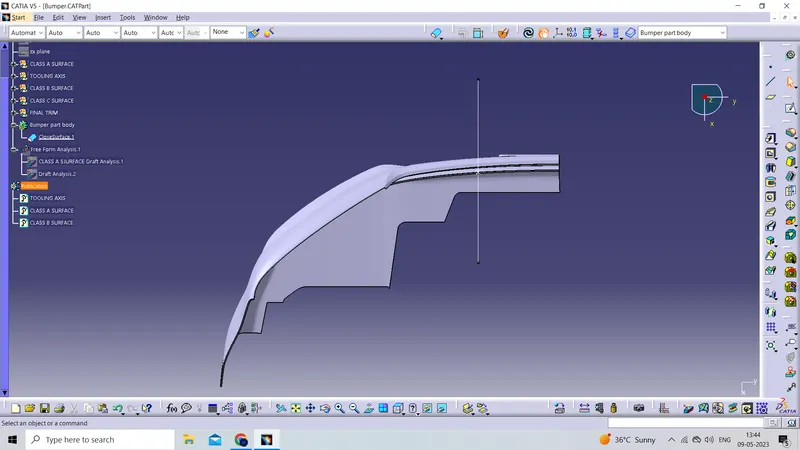
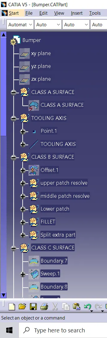
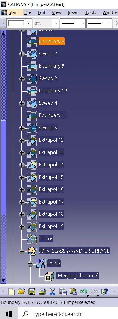
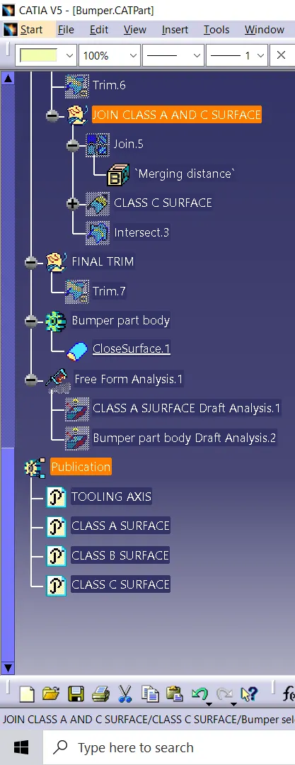
FEATURE TREE