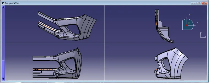
Week 9 - Challenge 3 - Bumper
Aim: Create the Bumper Plastic component through the give Class- A surface. To begin with, the tooling axis for the given Class-A Surface should be created meeting the requirements of the draft angel and at the end perform the Draft analysis on the model.
Main Objective:
- Tooling Direction Axis
- Draft analysis
- Class-B surface creation
- Class-c surface creation
- Closed body
Tooling Direction Axis:
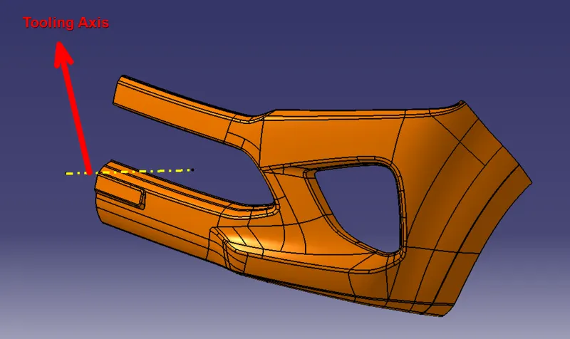
Tooling direction axis create main points.
- All direction checks which is maximum side visible.
- This bumper is X direction for maximum side visible.
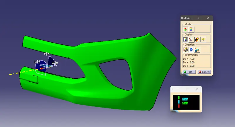
Draft analysis:
- Draft angle is 3 degrees.
- first of all, Compass is place for the Tooling Axis.
- After Compass is lock.
- Then select up side.
- Next analysis color changes for green or red which side effect for color.
- Green color is prefect and red is not perfect.
Class-B Surface Creation:
Main points for Class-B surface creation-
- Offset
- Boundary
- Extract
- Extrapolate
- Trim
- Edge Fillet
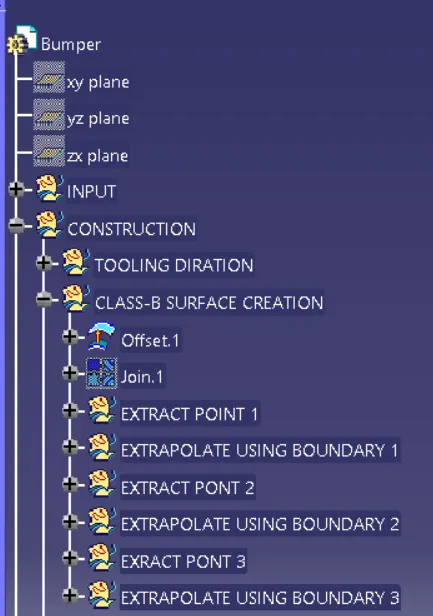
Bumper is complicated product. so first of all, create boundary or offset is 3mm then check for patches. Show in images below.
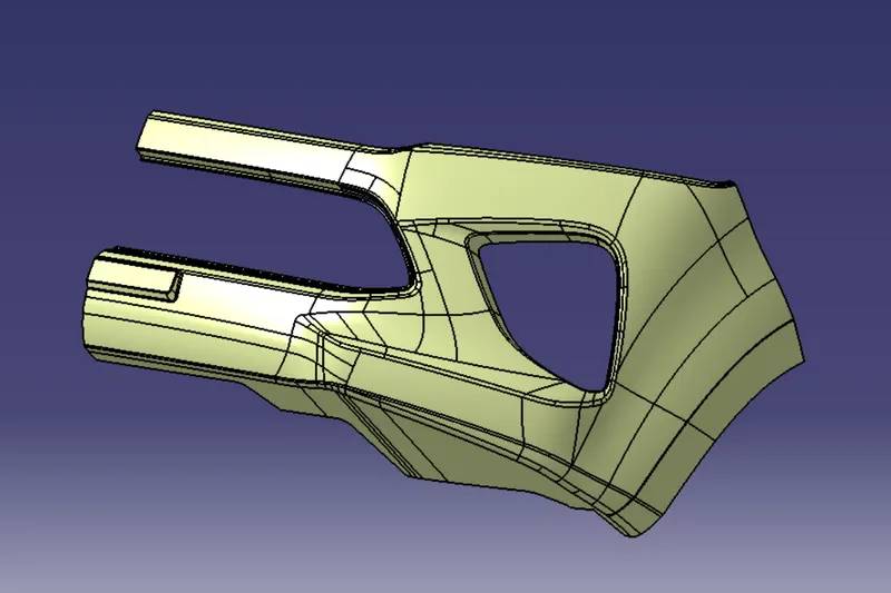
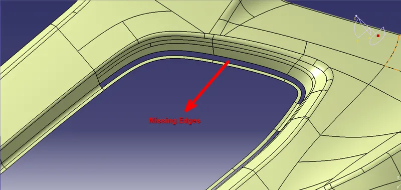
Patches resolve for extrapolate operation. Boundary creates and then extrapolate 4mm.
Class-C surface creation:
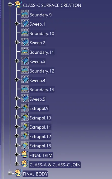
- Class-A surface to use for Class-C surface creation.
- First of all, check for tooling axis to parallel or perpendicular Class-C surface then create the surface.
- Use swept for with reference surface and with draft direction. (90 and 3 degree)
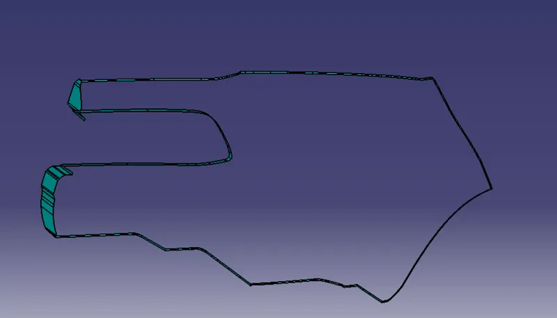
Final product view:
Thickness of the component to be 3 mm