Week 12- Final project
FINAL PROJECT-DOOR TRIM LOWER PANAL
Aim : To create a CAD Modal for Door trim Panel Components (Arm Rest,Lower Substant ,Bottle Holder,Map Pocket ) by considering the given inputs of Class A surface along with master section following the design rules considering following inputs as like in OEM and tier1 companies.
Objective :
- Creating a product file with all the parts
- Creating of Proper tooling Direction following section to create the part that meet the requirement .
- Draft analysis check to make sure that the class A surface is meeting the draft required along the tooling Axis.
- creating of class B and class C surface .
- Creating B side Engineering Features .
- Draft Analysis of the solid Body along with B side Feature .
- Assemble Push clip .
Procedure :
Given Class A Surface .
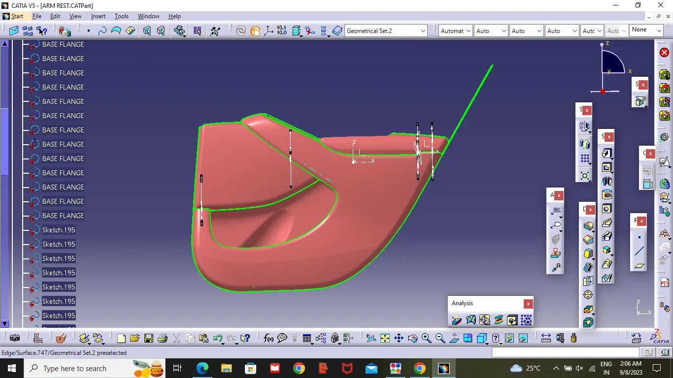
From the given Class A Surface , the component is Divided into 4 Parts
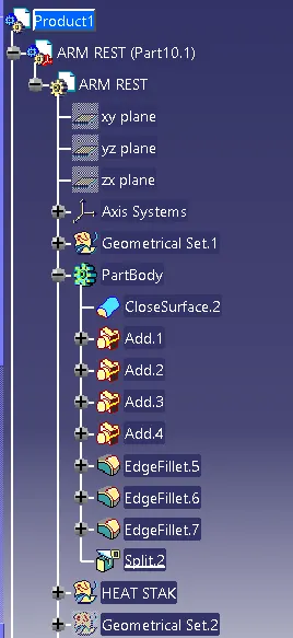
- Arm Rest
- Lower Substant
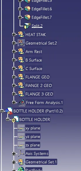
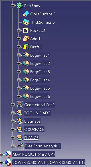
- Bottle Holder and
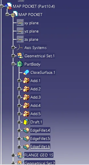
- Map Pocket.
ARM REST
Given Class A Surface for Arm rest .
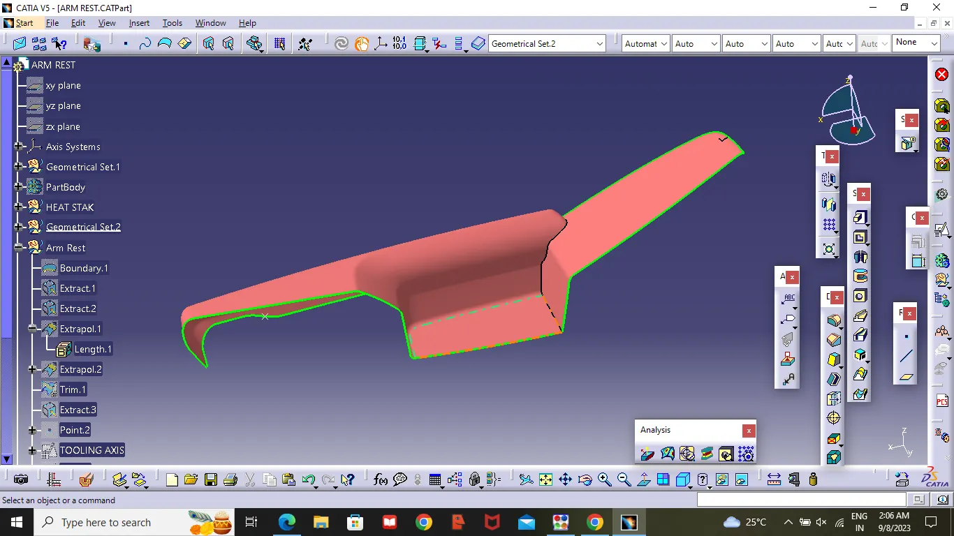
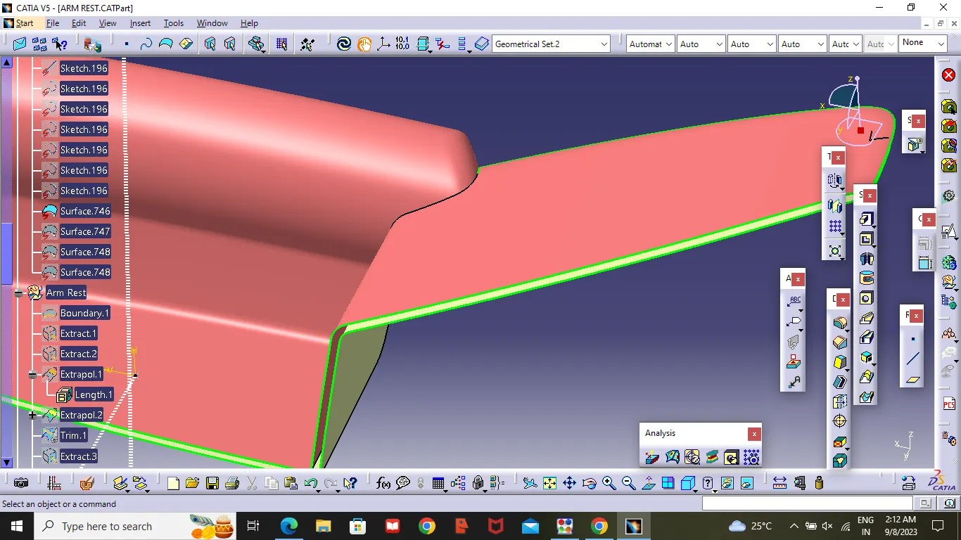
First Check the Class A surface whether it is having any open surface are not ,by using the Boundary option you can check the component .
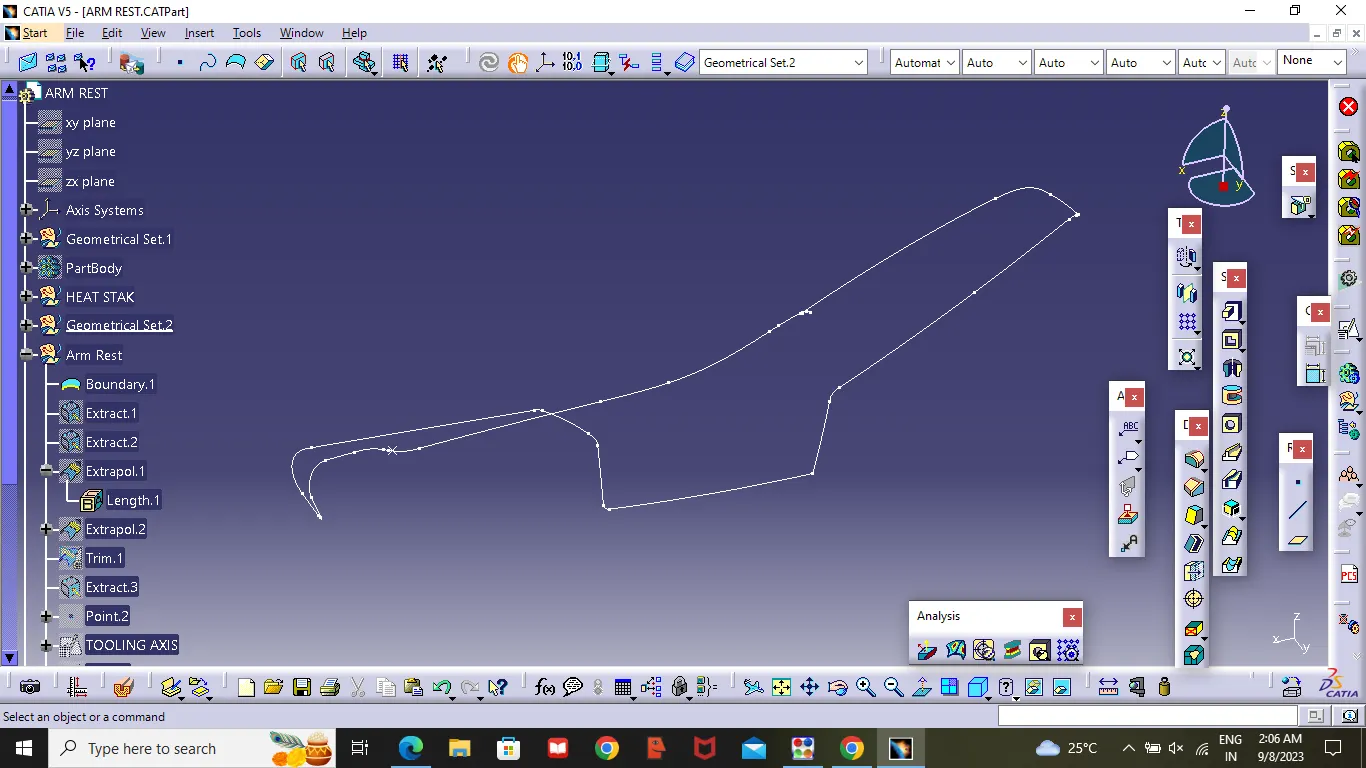
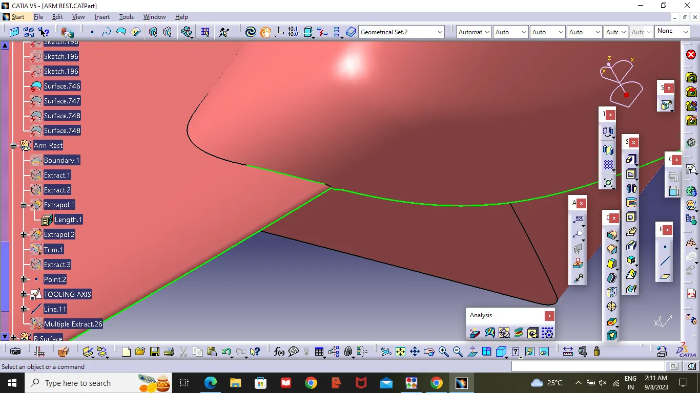
So in this Class A Surface there is one open surface at Corner ,as showen in the figure .so we closed the open surface by using extract and trim commands .
Tooling Axis:
To create a Tooling Axis first the Base part of class A was extracted and a point is created on the base .Based on the point we extracted the line . In this Arm rest we need to create two tooling Axis one is main tooling Axis and another Axis is to clear the side core .
After Creating the tooling Axis ,check whether the tooling axis is correct or wrong .by using draft analysis .Keeping the compass on tooling Axis .
Draft Aanalysis,
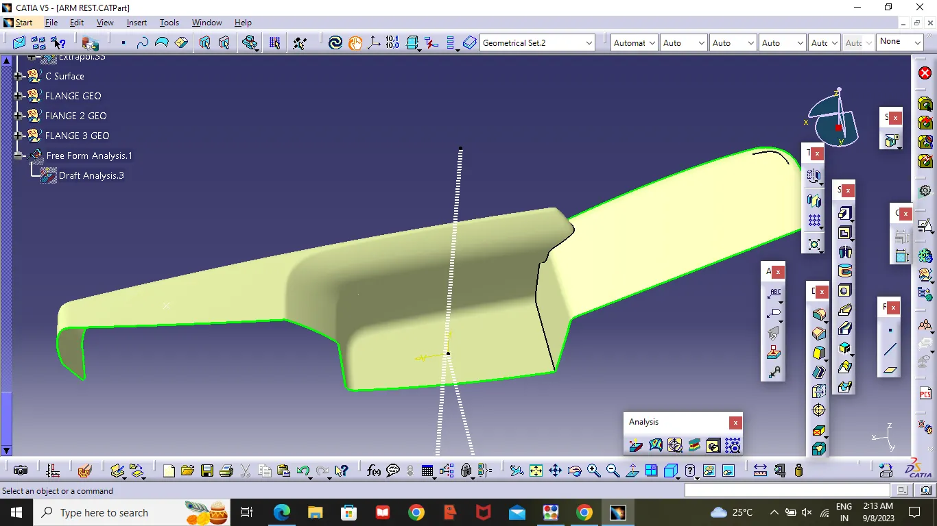
After completing the tooling Axis analyze the draft for the class A surface with a draft angle of 3 Degree. so it is clearing the surface with respect the tooling axis .
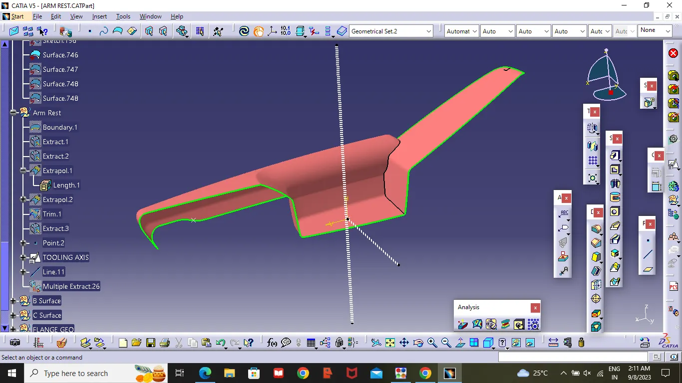
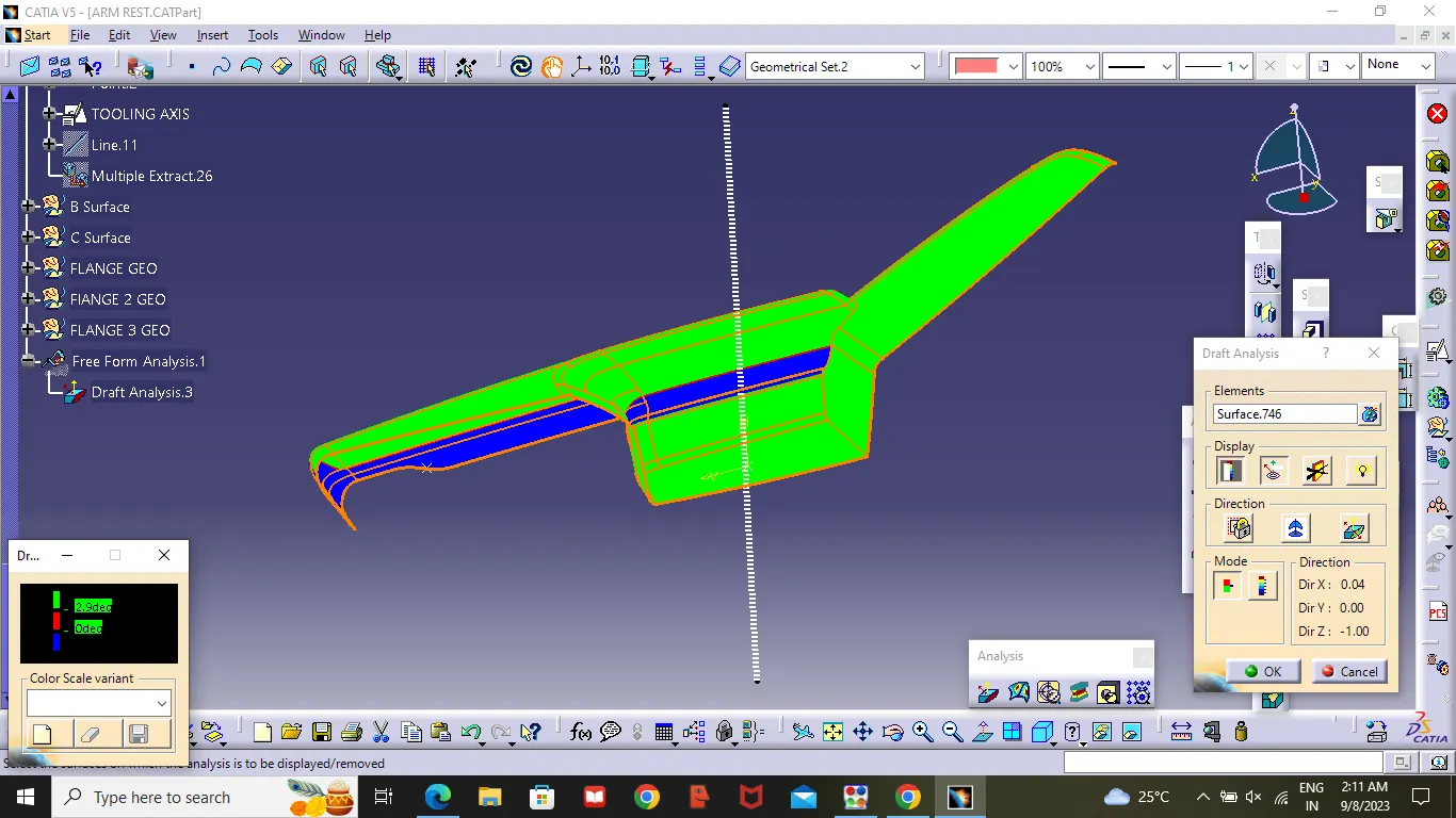
Here one tooling Axis is not Clearing the Draft Analysis ,so we are using two tooling Axis ,one is core and another is side core Axis.
Class B surface :
After completing the Tooling Axis ,Insert a Gemontrical set name it as Class B ,first we need to offset Class A surface to 2.5mm in inside direction to the component. After offset, will get some open Patches, by using the Multi-extract and option(with reference surface ). I have closed all the open Patched . and checked Class B surface whether it is having any Patches by using Boundary option .
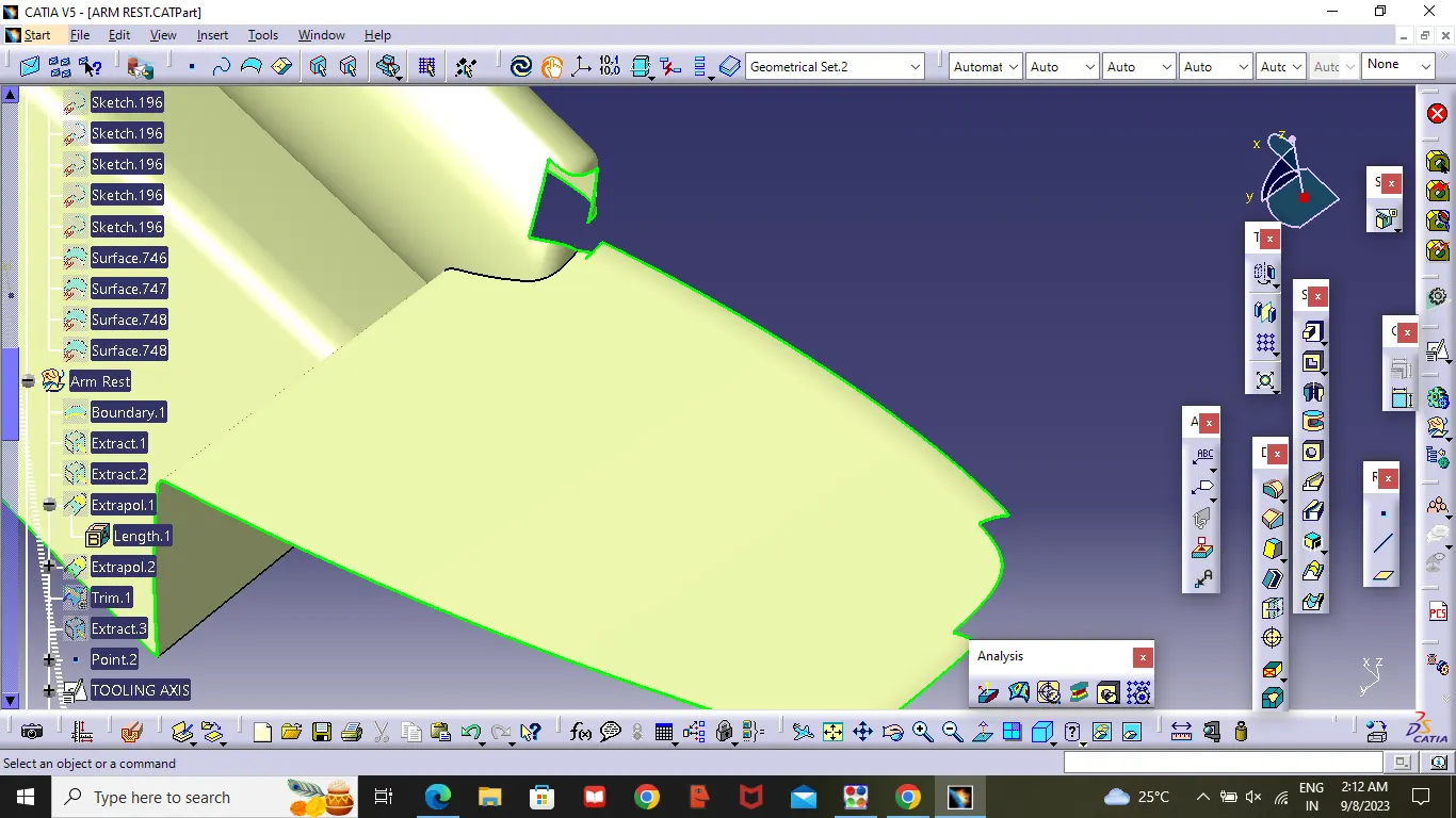
now the class B surface is good
Class C surface.
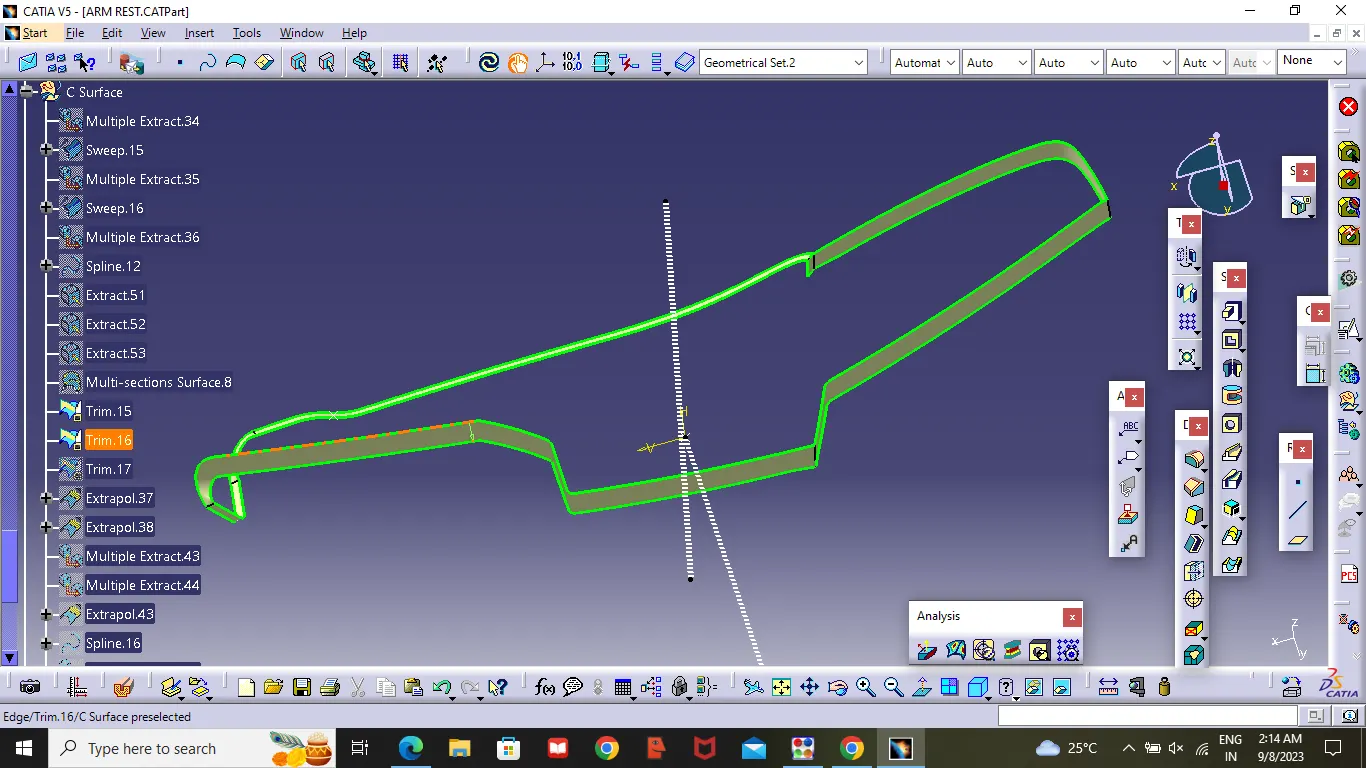
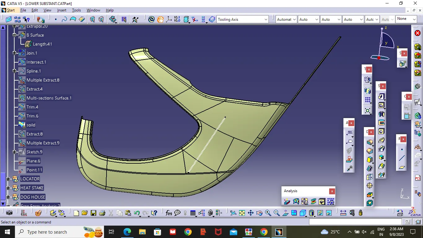
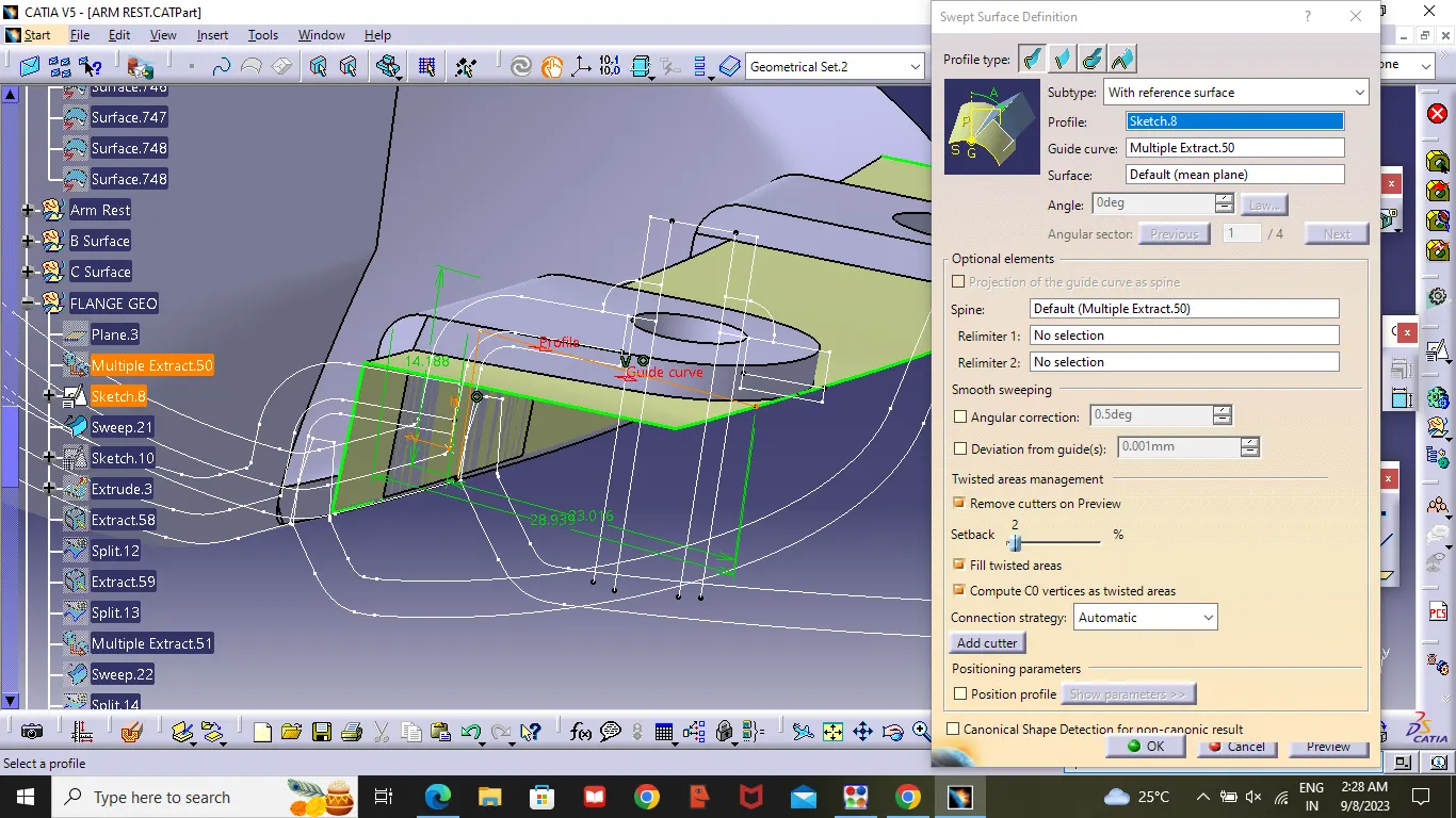
After completing Class B surface ,Unhide the class A Surface ,create Boundary lines by using extract or boundary command , after getting the lines , by using swept command we create a extand of class A at 3 degree .As showen in the figure . after completing the class c surface unhide the class B Surface.By using the trim option trim the extra surface from class A and Class C. then we will get a Closed Surface . After getting the closed surface . check the component whether it is have any open surface in the middle . our's component is closed component . so we can convert the Surface to closed material by going in the part design then to closed surface option .
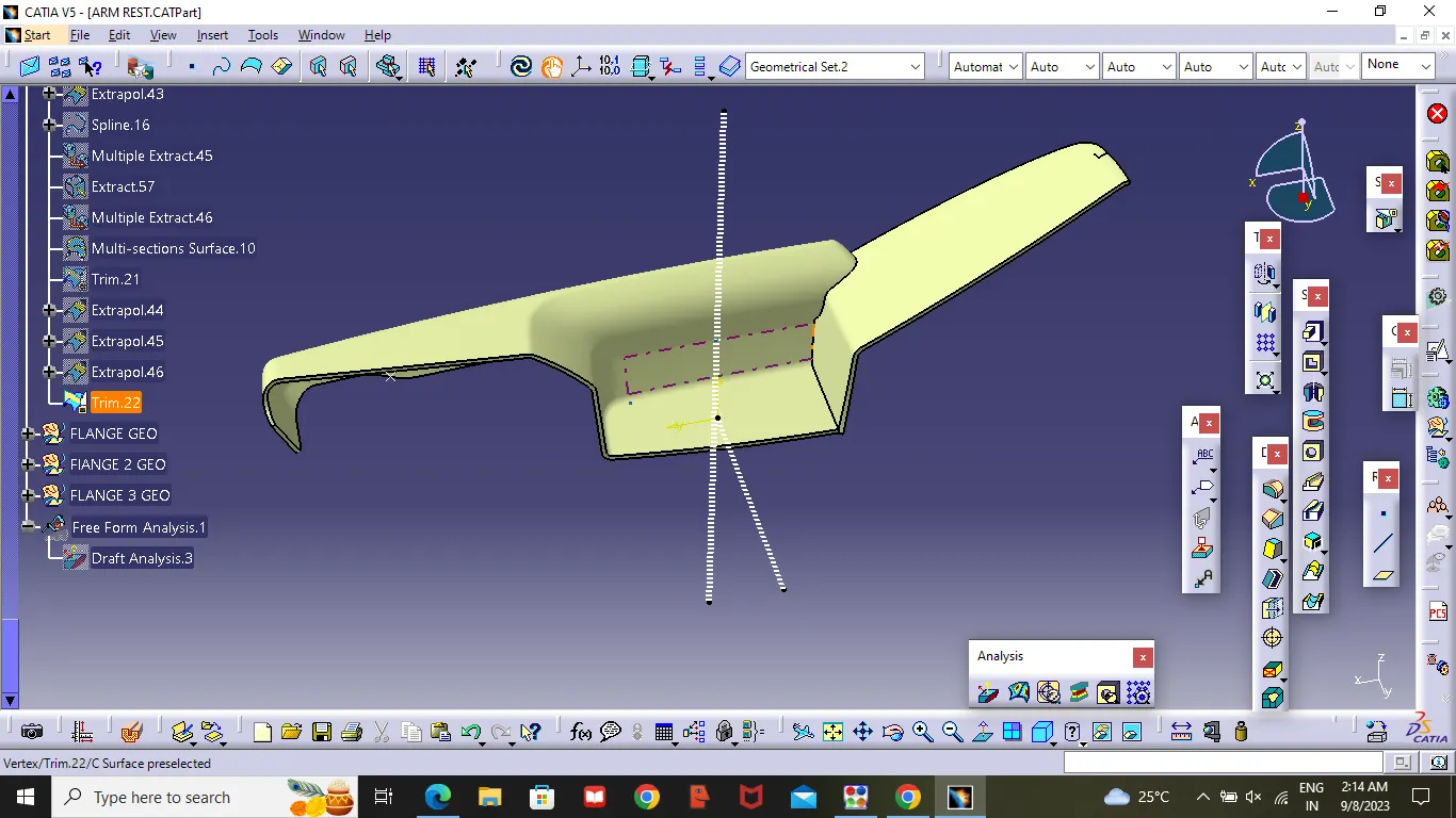
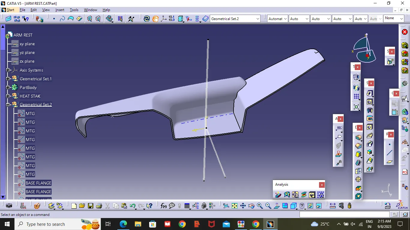
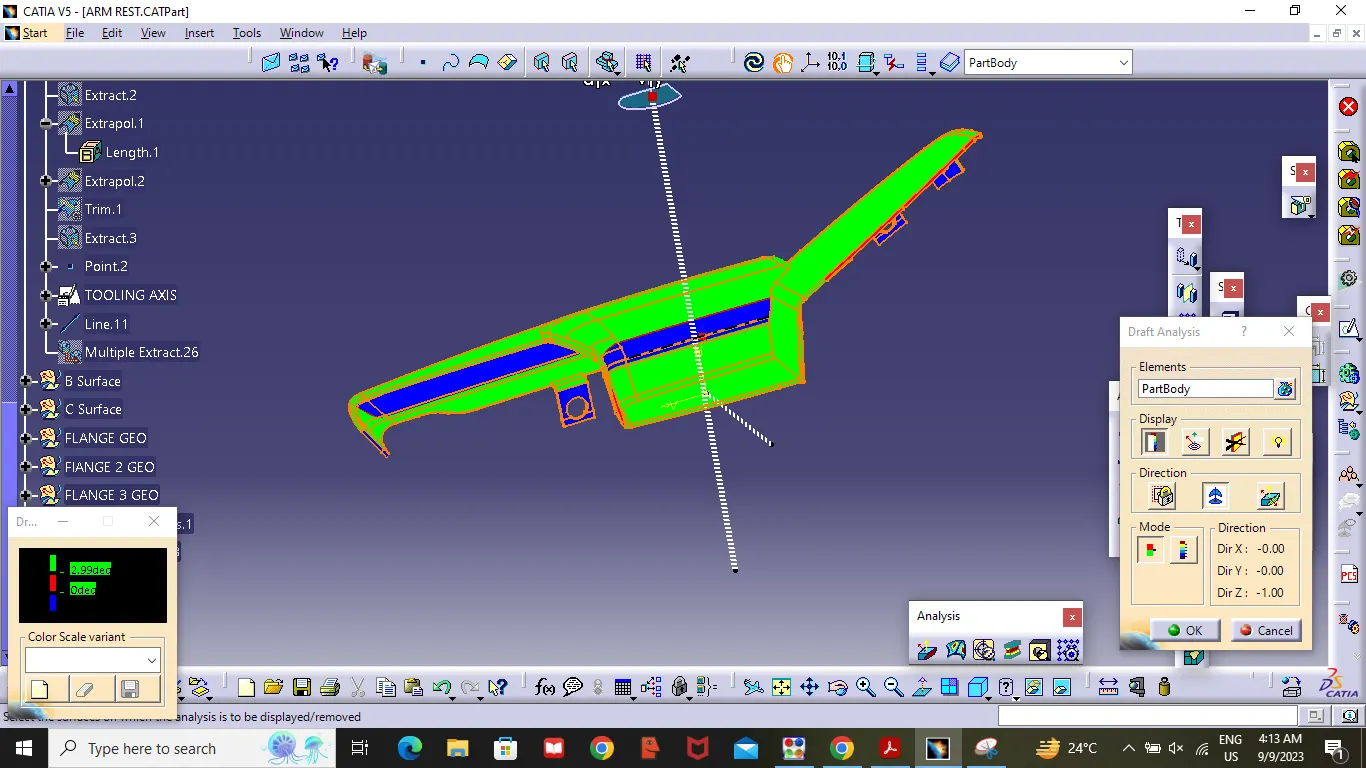
From the above Draft analysis we have notised that there is lot of Improvements of Class A surface .we have to send a report to Class A Team.
Lower Substant:
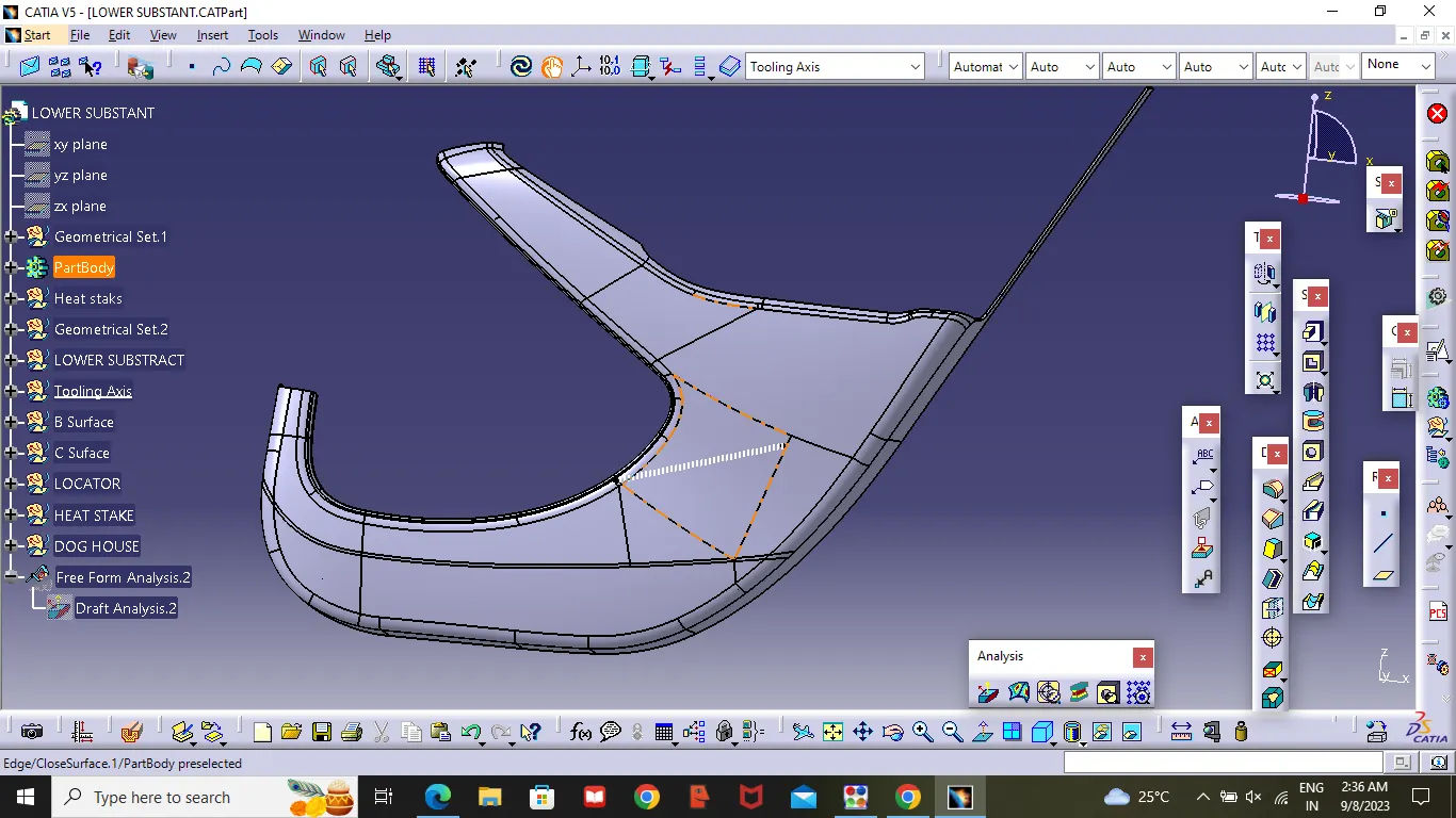
Given Class A surface of the lower substant .
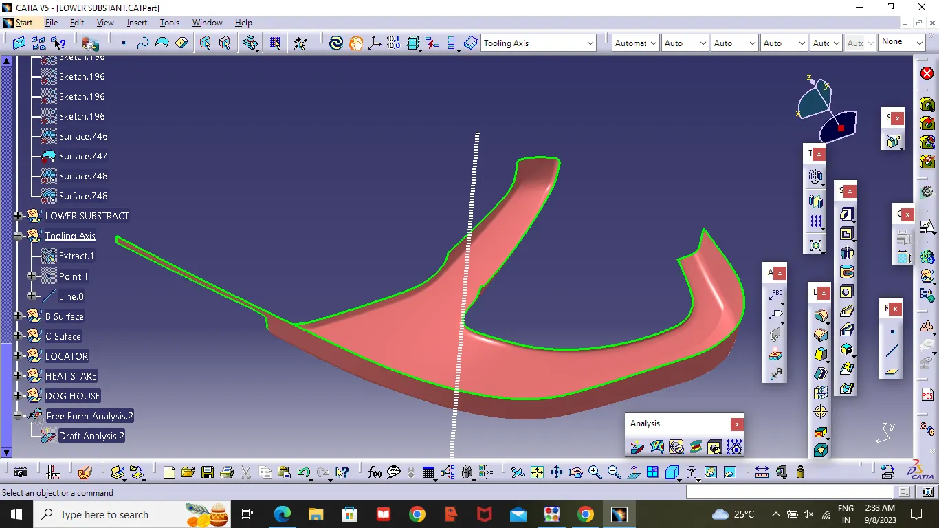
Check Class A surface have any open surface are not by using boundary ,in this component there is no open surface .so we need to create a tooling Axis which will clear the Draft.
Tooling Axis :
Extract the surface and create a point on the extracted surface and make a line on that point with respect to the Y-direction ,see that the tooling axis is clearing the draft or not
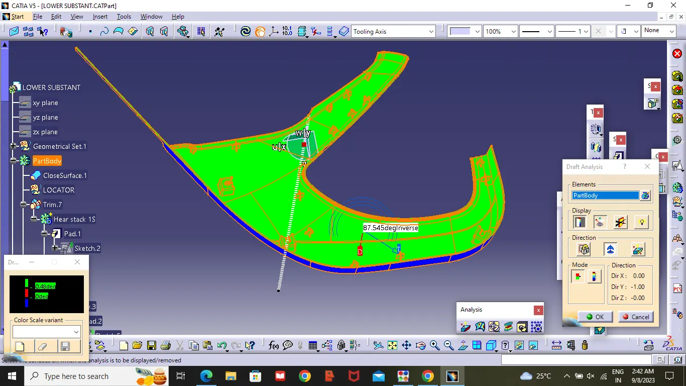
Draft Analysis
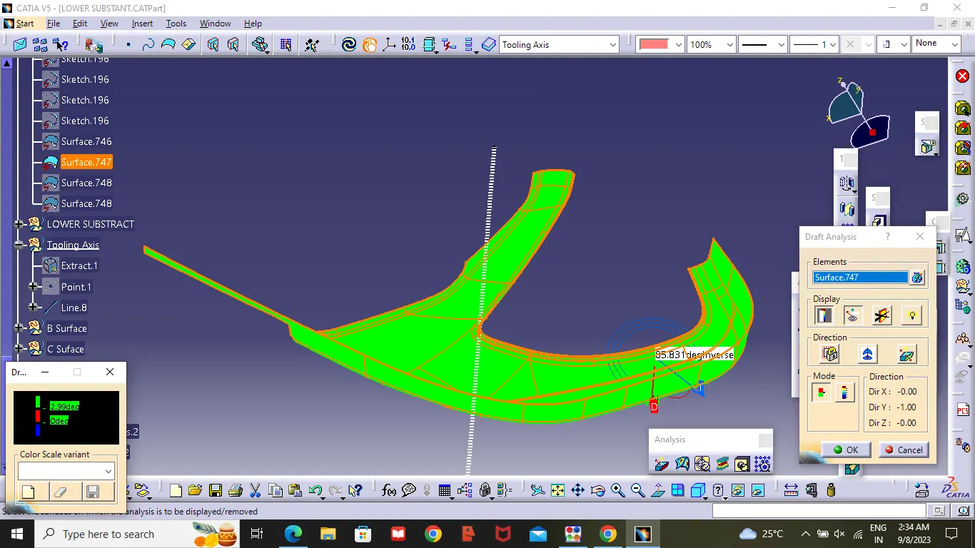
The Class A surface is Completely Clearing the Draft Analysis of the 3Degree with Respect to the tooling Axis
Class B surface
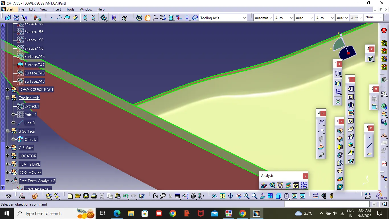
- After completing the tooling axis , create class B surface by offseting the class A surface to 2.5mm in inside direction to the component .as showen in the figure .
Class C surface :
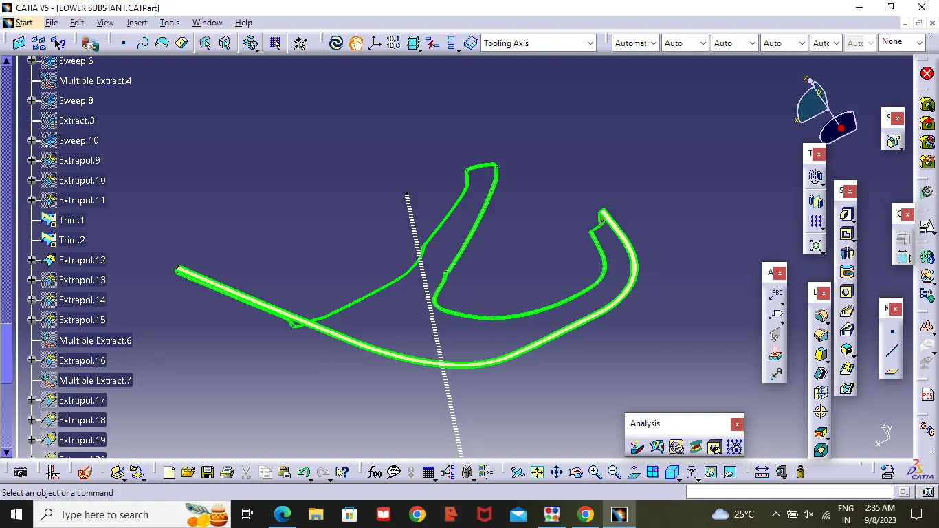
To create a class C surface ,when the class C surface is parallel to the tooling Axis then use the sweep command with respect to the draft direction to an angle of 3 degree.if class C surface perpendicular to the tooling axis then make the sweep with the reference surface with 90 degree.
MAP POCKET:
Map Pocket is the Sub Element which is located at right side to the lower substant of the door trim panal .
Given class A surface of MAP Pocket
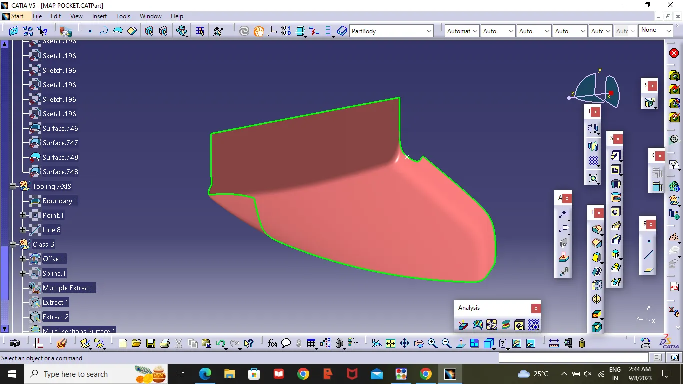
Check whether the Map pocket surface is having any open surface in the middle ,by using boundary surface command ,hence our map pocket surface is not having any open surface ,so we can proceed with tooling axis
Tooling Axis :
In this case first extract the middle surface of the map pocket and set a point on the extract surface and create a line with respect Y direction(point to direction).
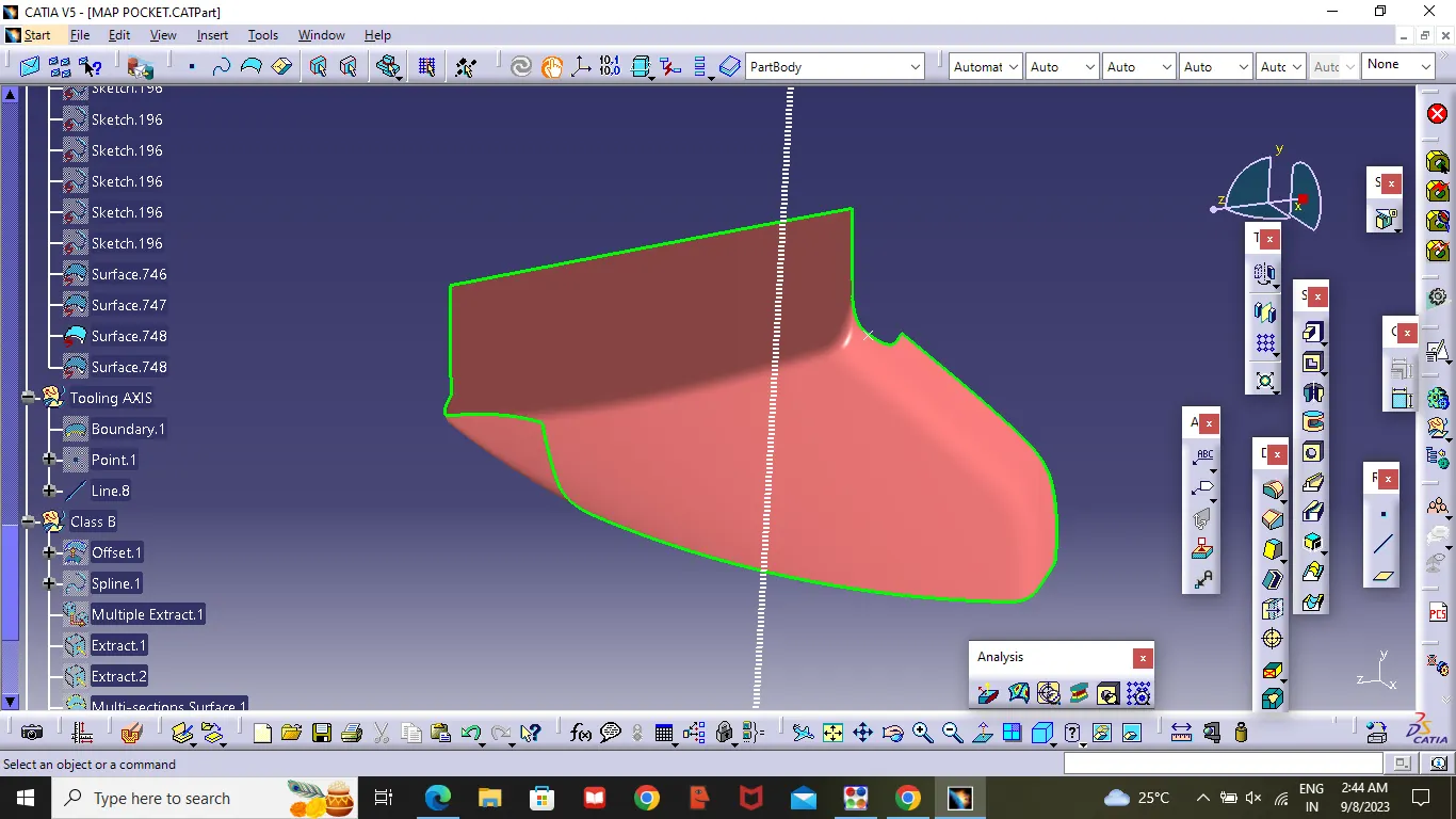
Draft Aanalysis,
After completing the tooling Axis analyze the draft for the class A surface with a draft angle of 3 Degree. so it is clearing the surface with respect the tooling axis .
Class B Surface:
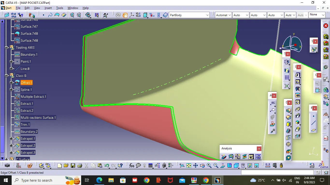
After completing the Tooling Axis ,create a gemontrical set and name it as Class B surface ,then offset the class A surface to 2.5mm inside direction,there will be some open patches in class B surface by using spline and multi-extract we can close the open surface .then extract the hole surface it 5mm , which help's in trimming the class B and Class C surfaces .
Class C surface :
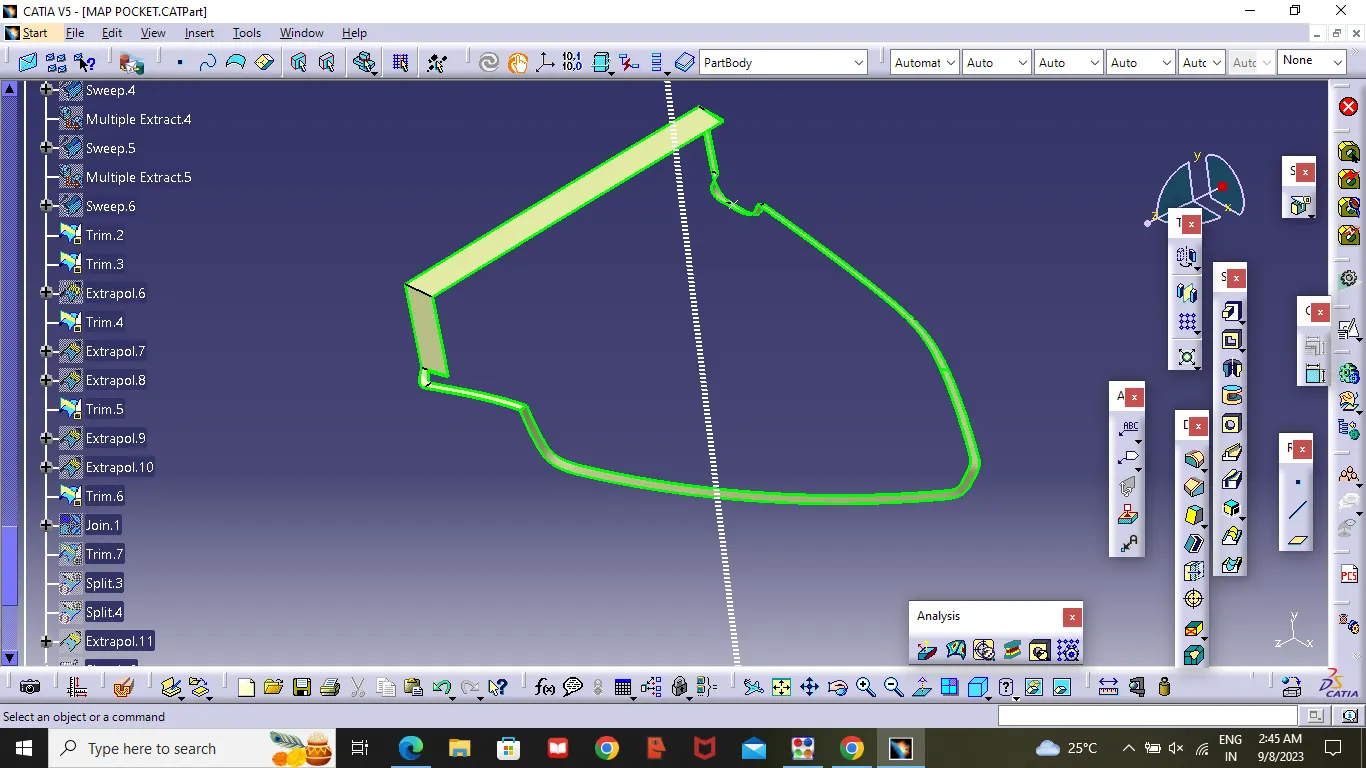
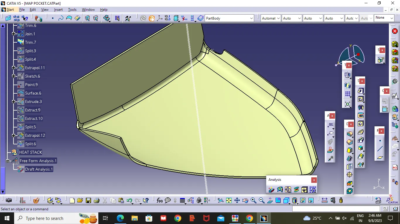
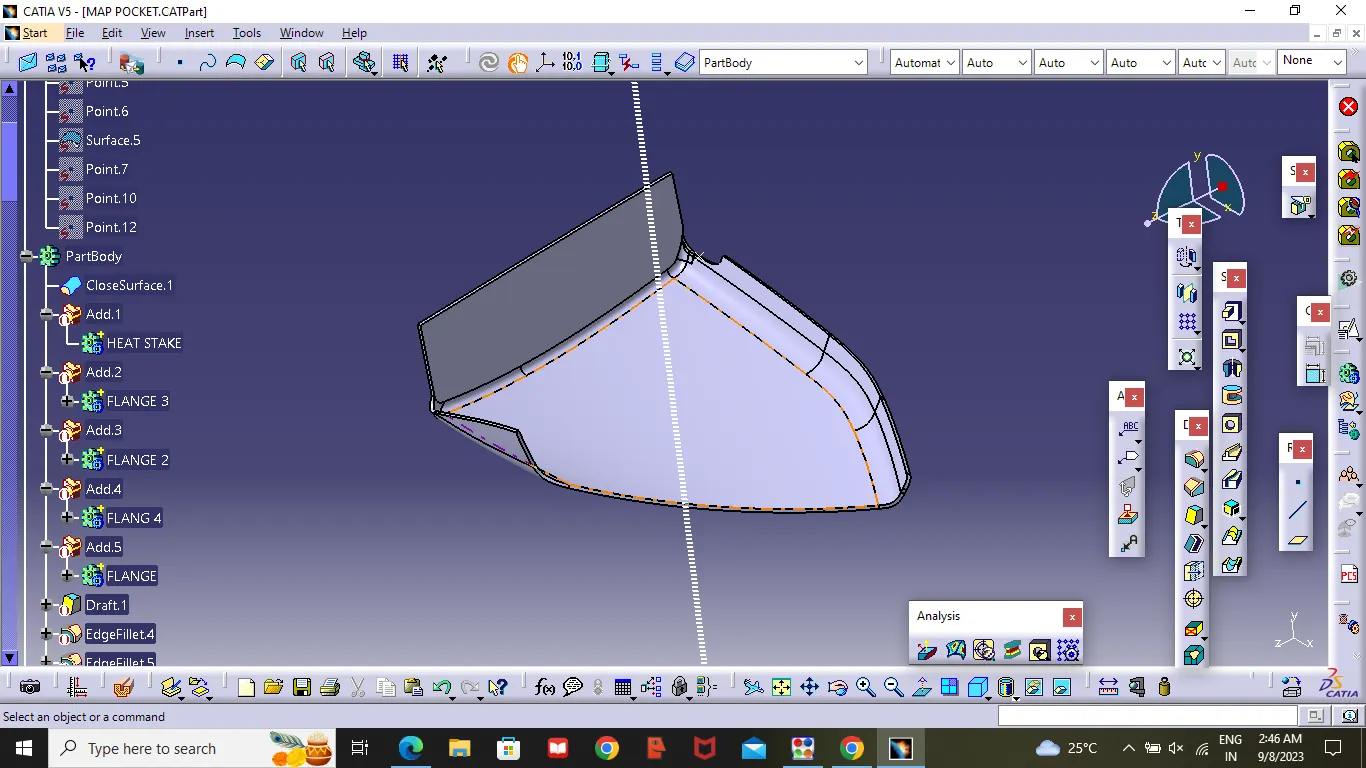
Now create class C surface by using multi-Extract ,Sweep Command and Trim Command .after completing the C surface join Class A Surface and Class C Surface . Unhide the class B surface then by using the Trim Option we will get the desire shape of the Component ,then convert the surface to Solid Body .
Draft Analysis
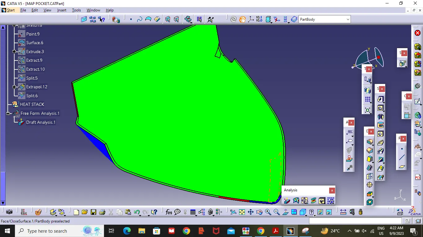
Here all the surface are clearing with the draft angle of 3 Degree .But some of the corner curvature are not be that perfect to clear the draft angle of 3 degree.
Bottle Holder :
Given Class A surface
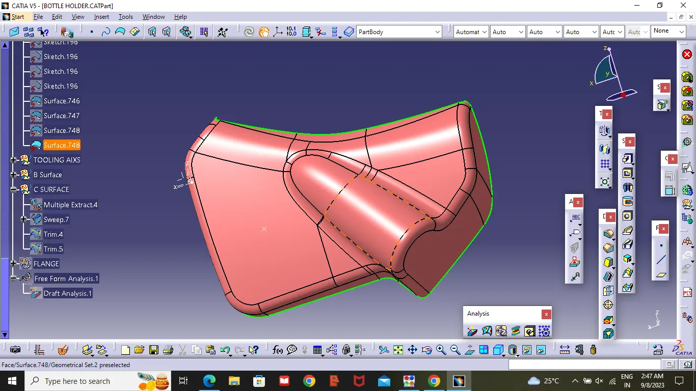
Continueing the same process ,checking that the surface is having any open surface are not ,in this bottle Holder there is no open surface ,so we can create the tooling Axis .
Tooling Axis :
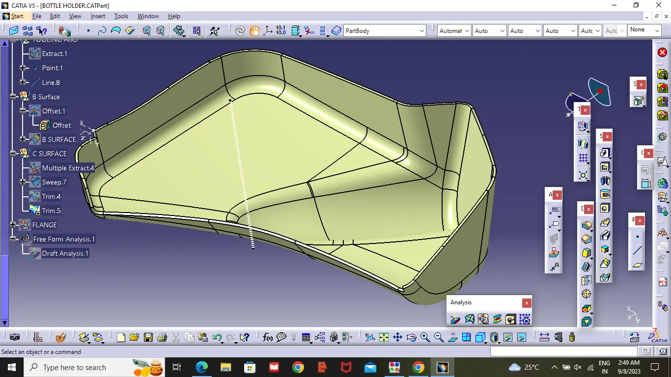
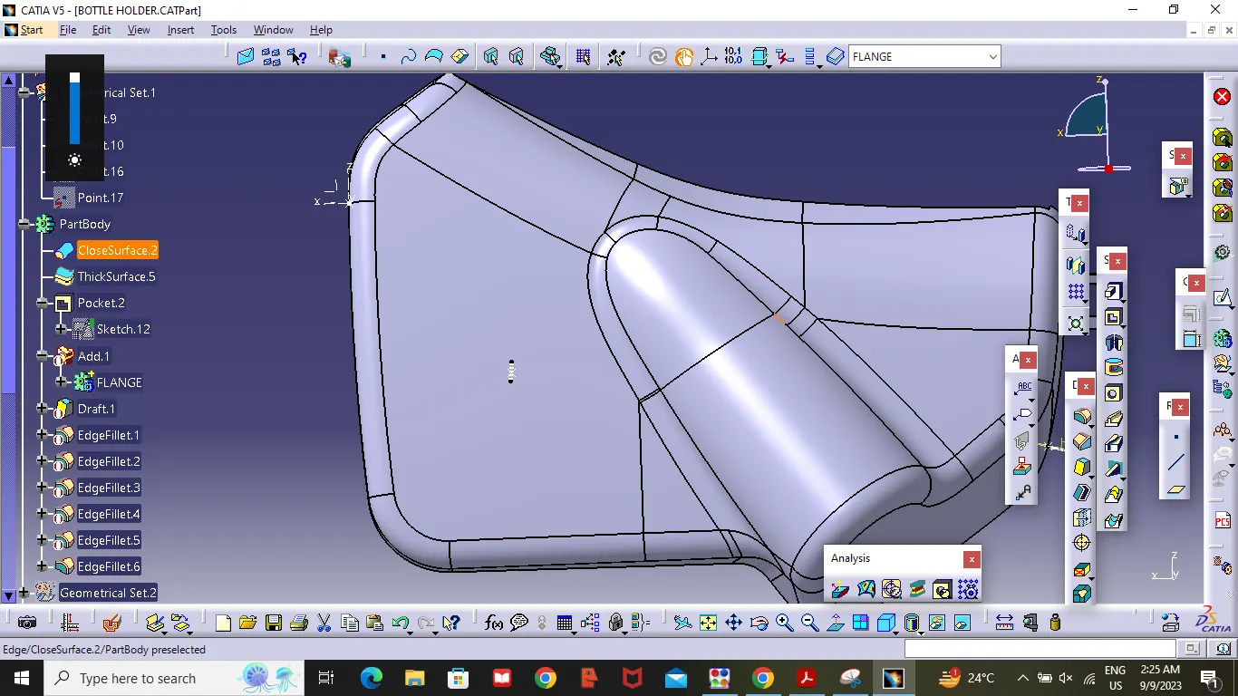
Extract the class A Surface in middle as showen in the figure , then create a point in the extract surface then create a line with respect the y-direction as showen in the figure .
Draft Aanalysis,
After completing the tooling Axis analyze the draft for the class A surface with a draft angle of 3 Degree. so it is clearing the surface with respect the tooling axis .
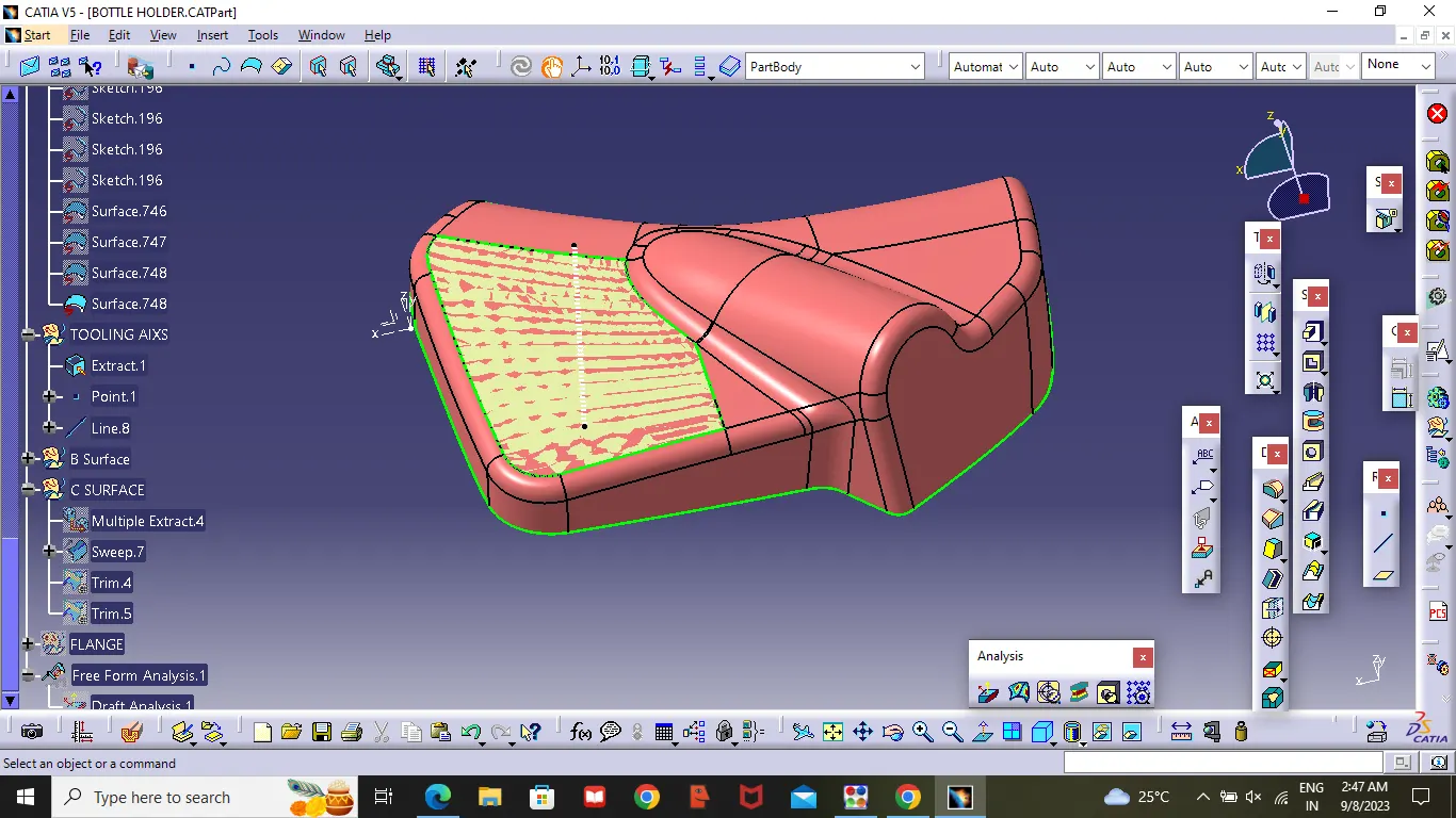
Class B surface :
After completing the class A surface ,offset the class A surface to 2.5mm ,in this bottle holder the B surface does have any open surface .so we can continue with class C Surface .
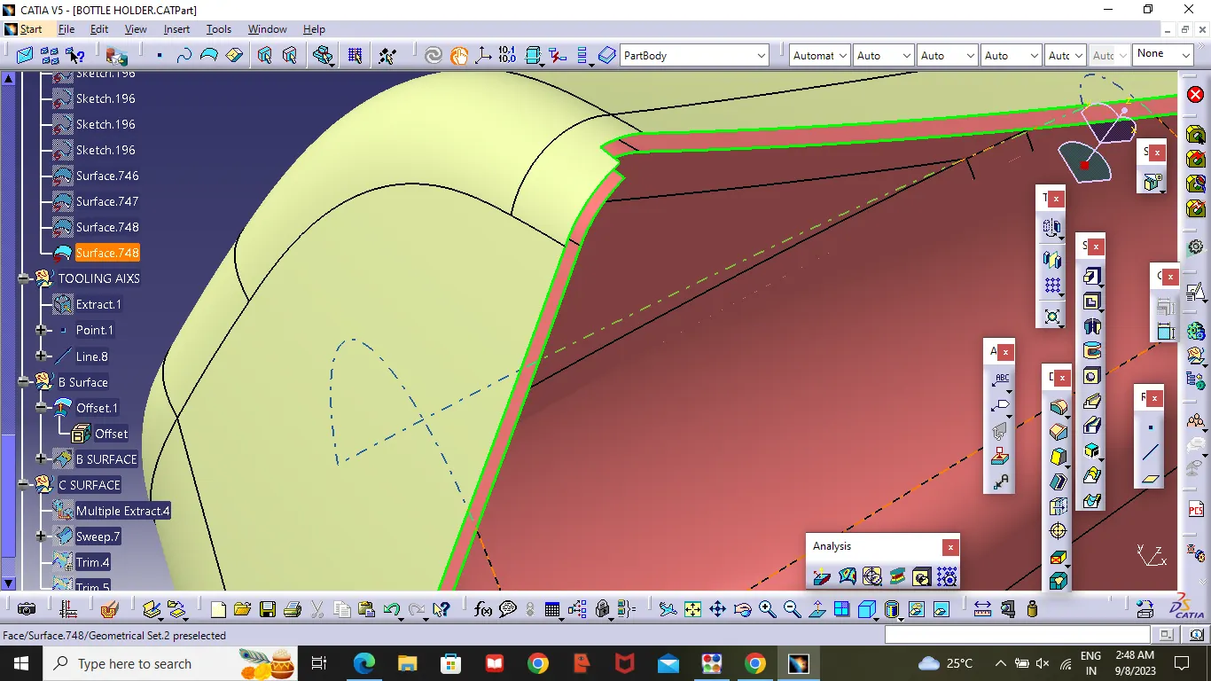
Class C surface :
Create Class C Surface by using Sweep Commant and Join the Class A Surface and Class C surface .then convert the surface into solid body by using closed surface in partbody .
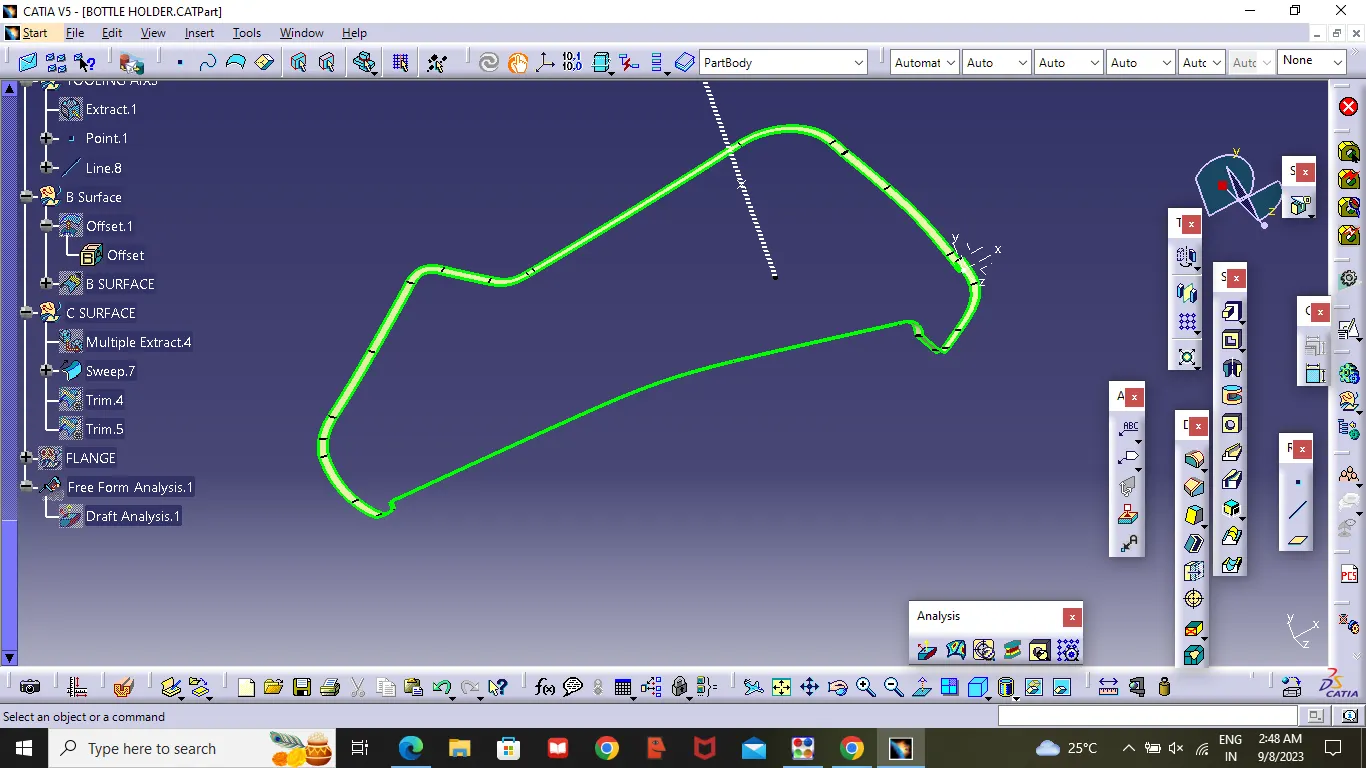
Draft Analysis
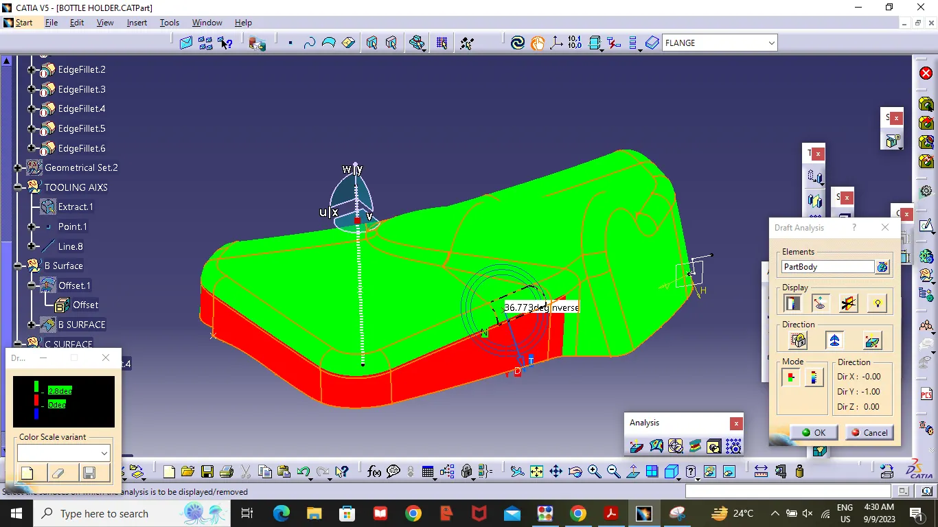
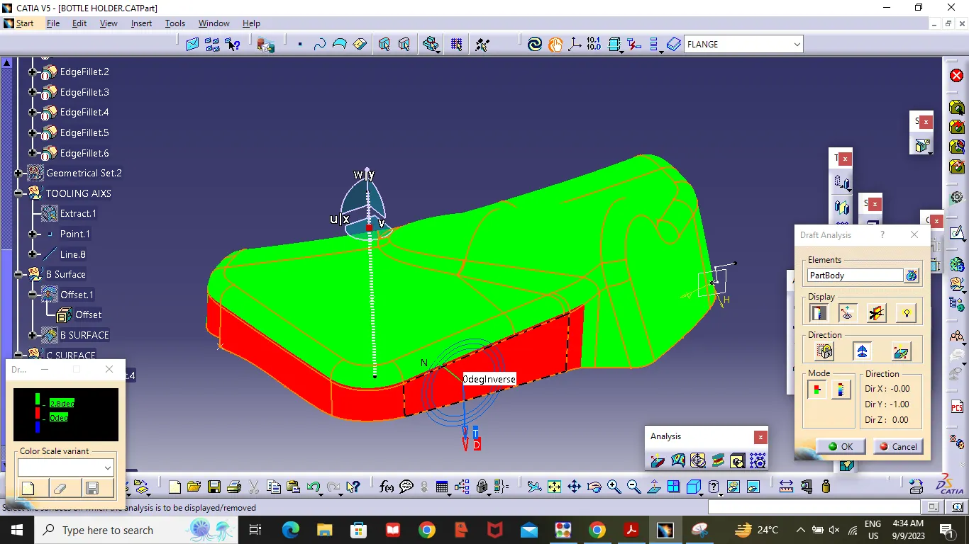
In this component the draft analysis of the patches are red the draft is 0 .so we need to report to the class A team as to draft on the given surface is not appropriate and need to get Modified.
B Side Engineering Features :
If all the components are converted to solid body then we move onto the B side Engineering Features .
Arm Rest:
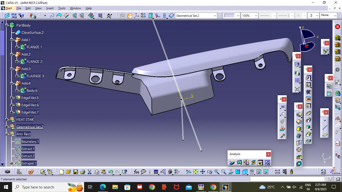
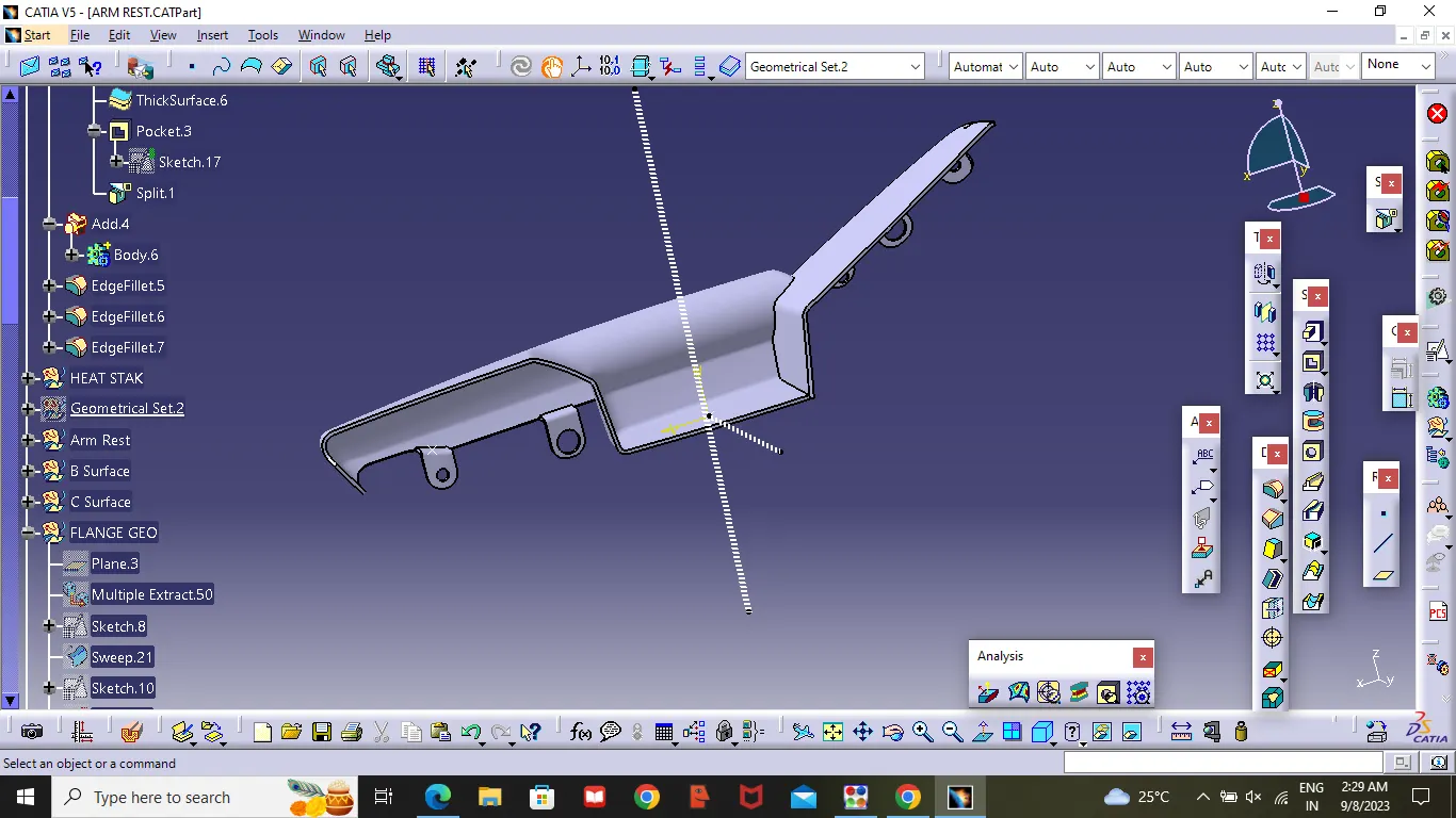
First Based on the master Section's Provided form the inputs surface the Arm rest is indicating that the Flanges are positioned on the surface .
Draft Analysis
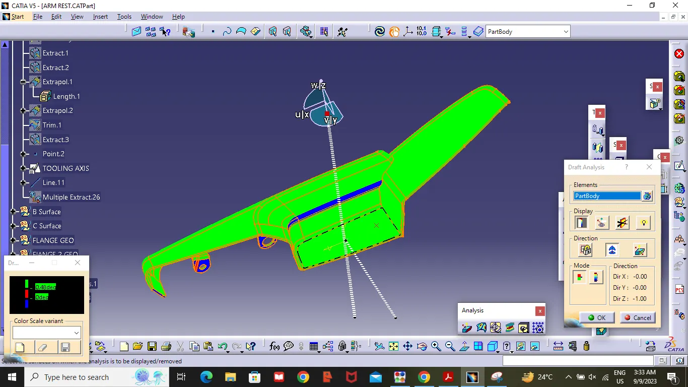
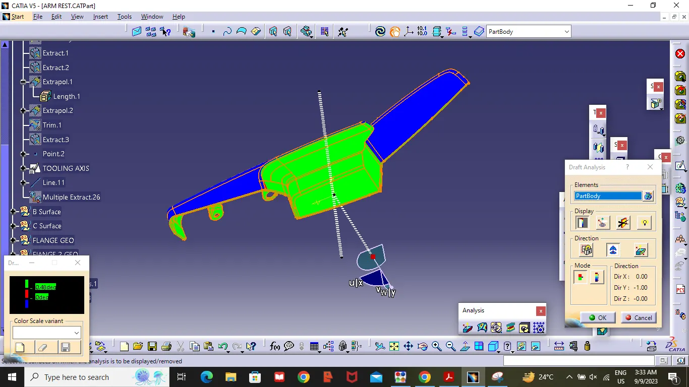
Here one tooling Axis is not Clearing the Draft Analysis ,so we are using two tooling Axis ,one is core and another is side core .but need lot of imporvements in class A surface
Lower Substant:
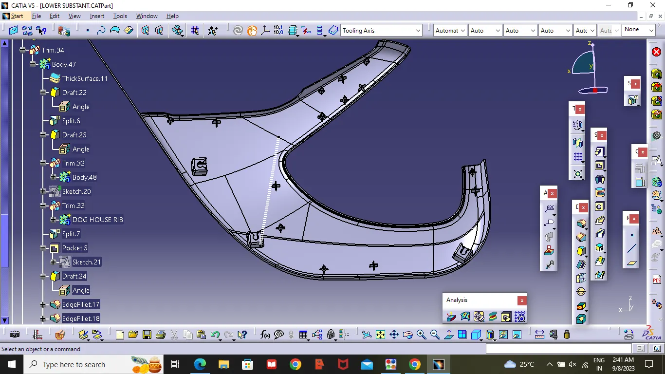
Based on the master Section's Provided form the inputs surface the lower Surface is indicating that the Heat Stake are positioned on the surface .
Follow the Master Section ,
Heat stake :
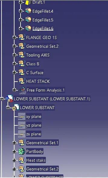
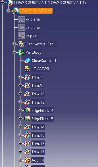
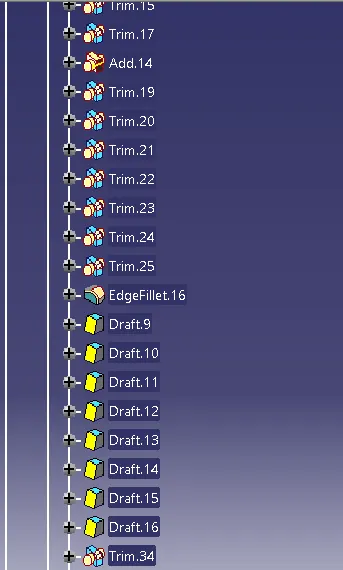
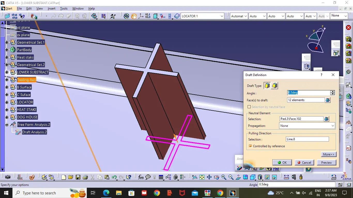
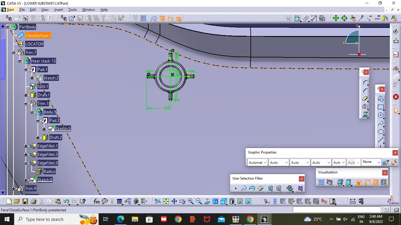
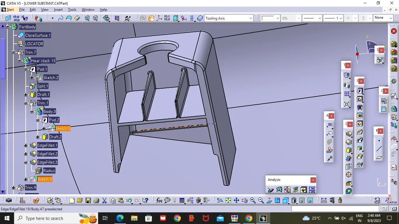
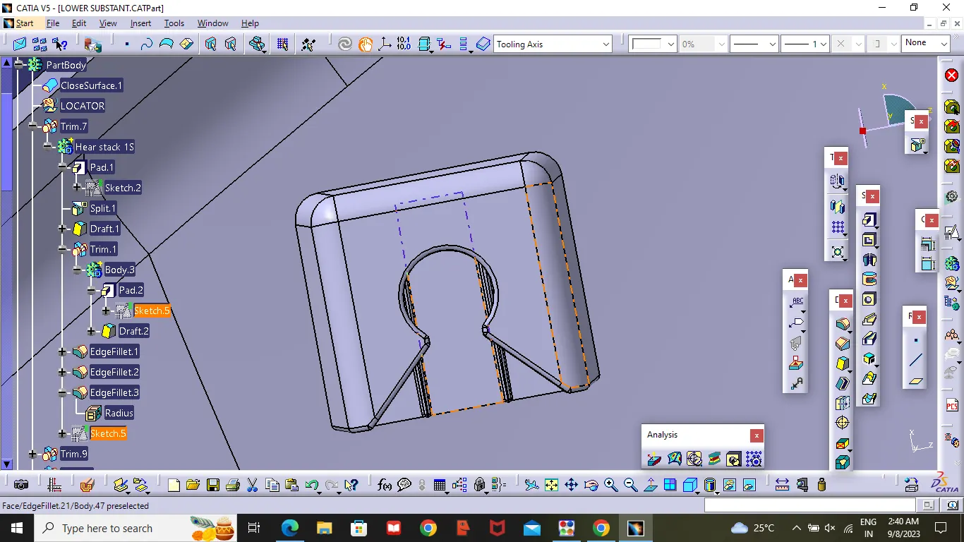
Create a sketch on the plane with respect to the given master section as showen in the figure .then pad it the sketched surface after that i have given a draft angle of 0.5deg on inside and out side of the heat stake ,after creating that i have created rib's for the support after that give draft for all the sides of ribs of 0.5mm with respect the tooling Axis ,fillet the edge with 0.25mm.
After creating one heat stake copy the body sketch of the heat stake and go to part body at it's Particular component click and select past specical then select as result with the line .then click transalation option point-point .select first heat stake point then select the point where it shoud be placed .
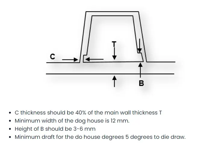
Procedure to Make Dog House :
Create a point on the surface and create plane on that point .As showen in the fig. Draw the Sketch On that Plane .
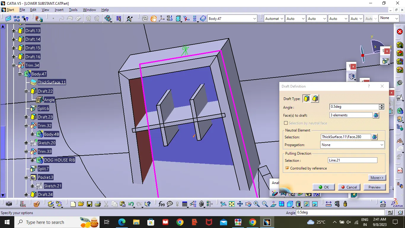
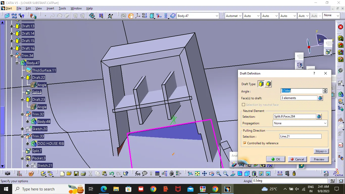
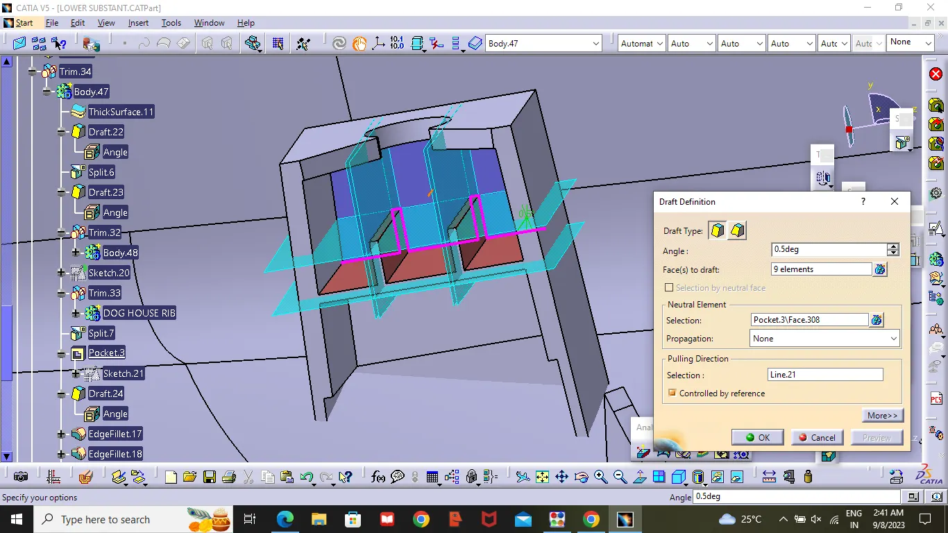
After creating the Sketch Use the Sweep commend to extraxt the Sketch at 1.5 Degree .After completing the side walls Create a Line on the point in Y-direction . Offset the Base Part to top of 26-30mm height ,after that using the trim option make it as a shell .
After getting shell insert a body and use Thicksurface command to shell in outer side with 2mm. then use draft command .draft the innter part at 0.5mm .Then use fillet commend to make the innter surface smooth .
After compleating this process offset the base surface to 3-6mm height and by using trim option make a small shell and then go to part design and choose Trim option and trim the step surface .
Locators :
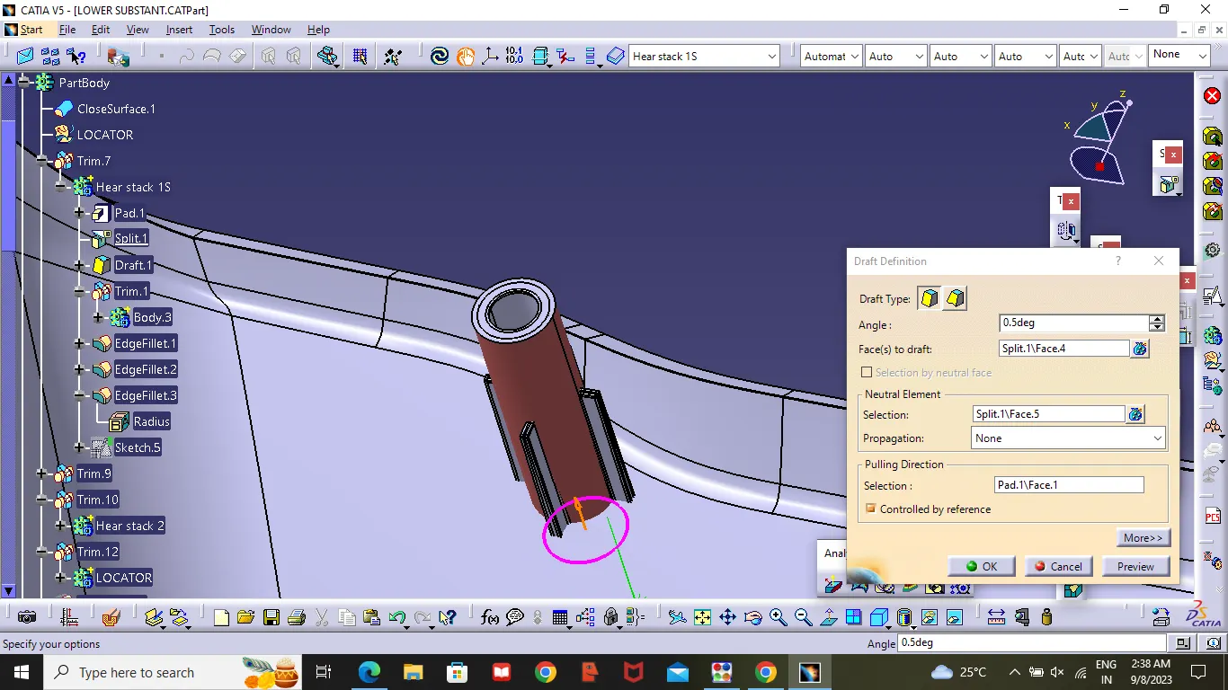
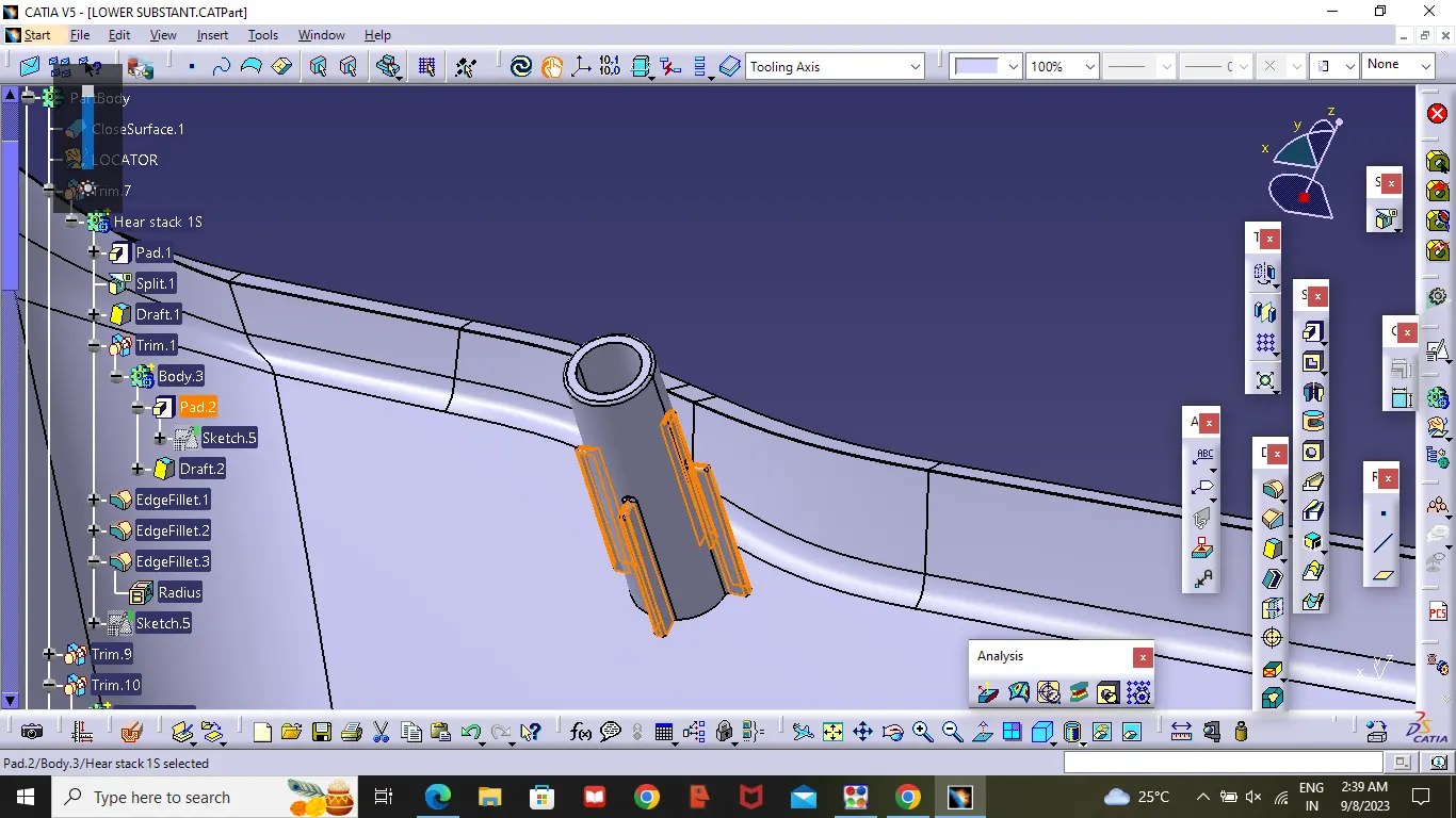
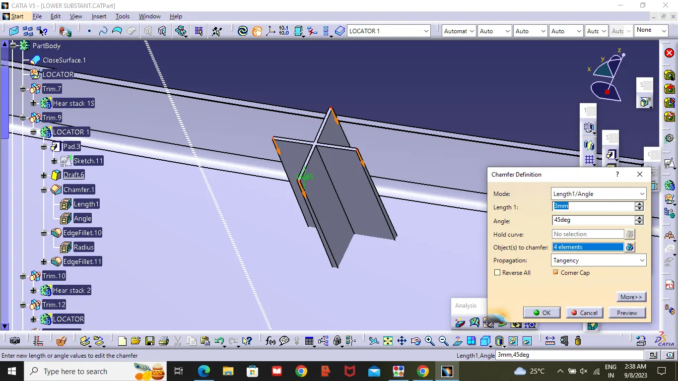
To Create a Locator I have taken a point and added a plane on that point ,then skech on the Plane ,After creating the sketch , Pad it. then draft it with 0.5deg in the direction of the tooling Axis .then i have given 3mm Chamfer with 45mmdeg of inclination and after then give fillet of 0.25mm radius .
Draft Analysis
Map Pocket
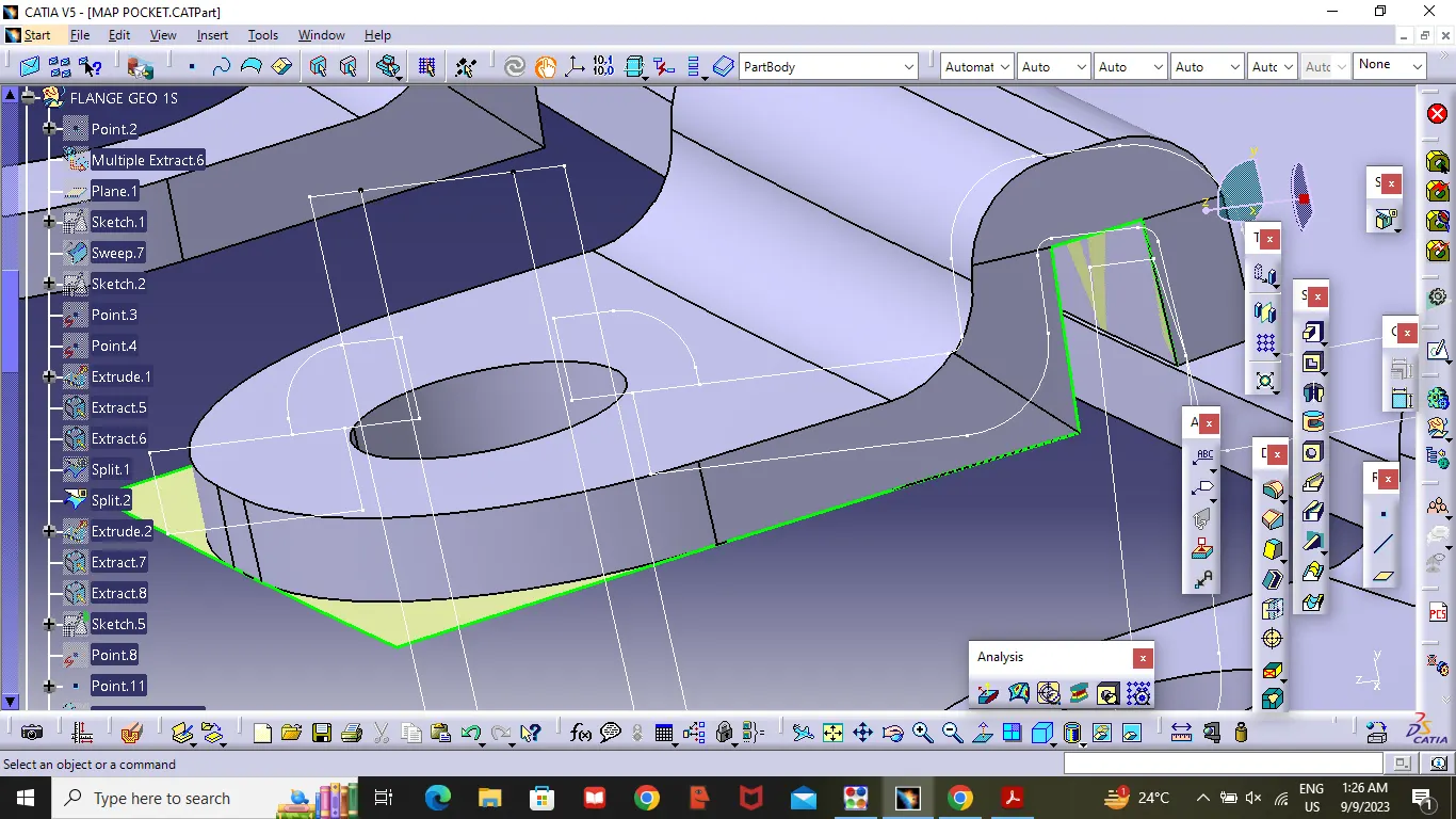
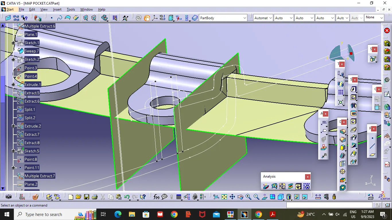
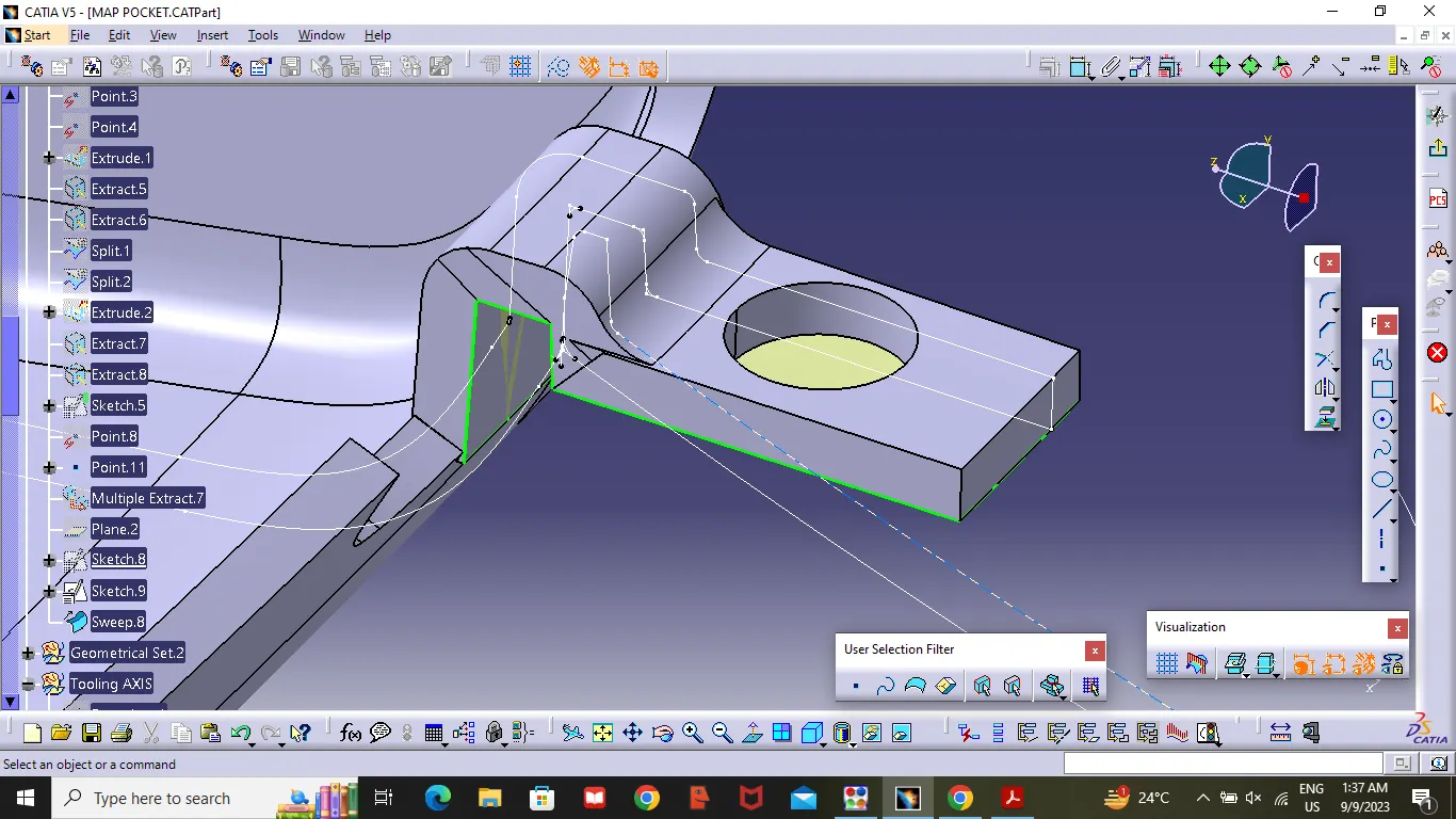
the master Section's Provided form the inputs surface the Map Pocket is indicating that the Flanges are positioned on the surface .
Draft Analysis
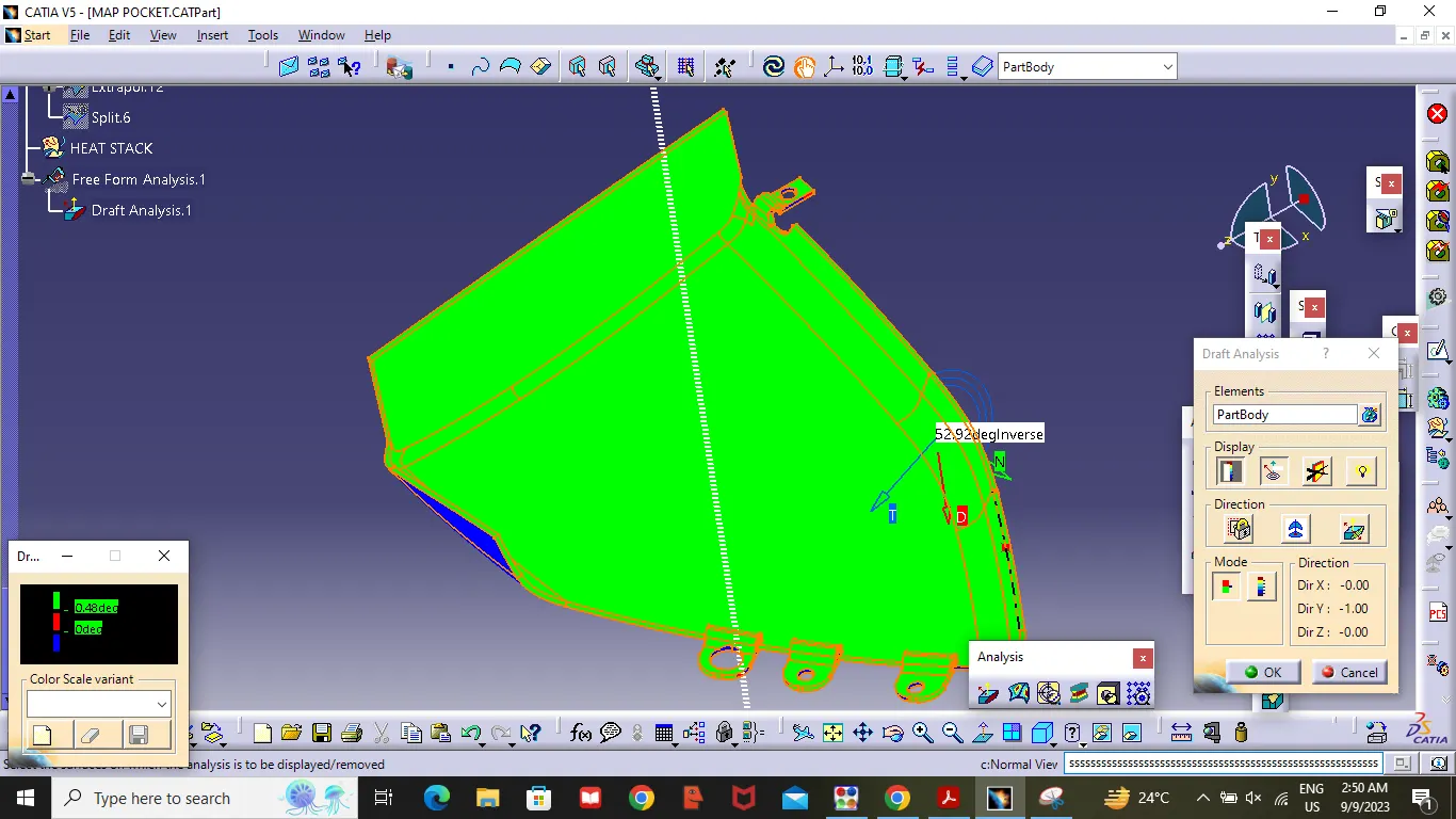
Here all the surface are clearing with the draft angle of 3 Degree .But some of the corner curvature are not be that perfect to clear the draft angle of 3 degree.
Bottle Holder:
The master Section's Provided form the inputs surface the Bottle Holder is indicating that the Flanges are positioned on the surface .
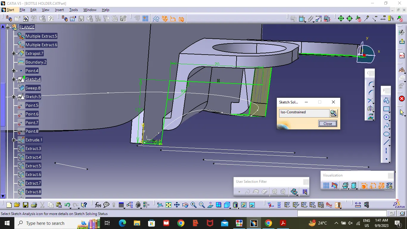
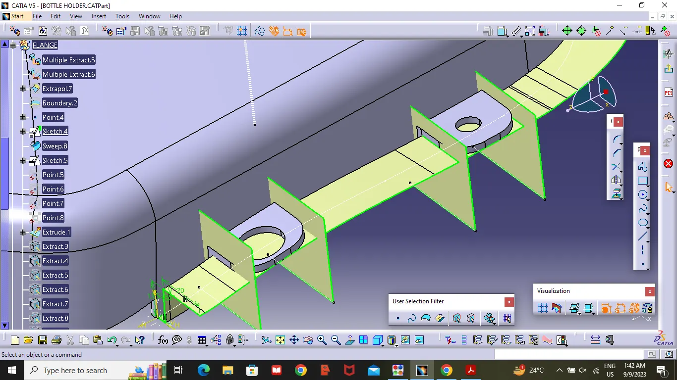
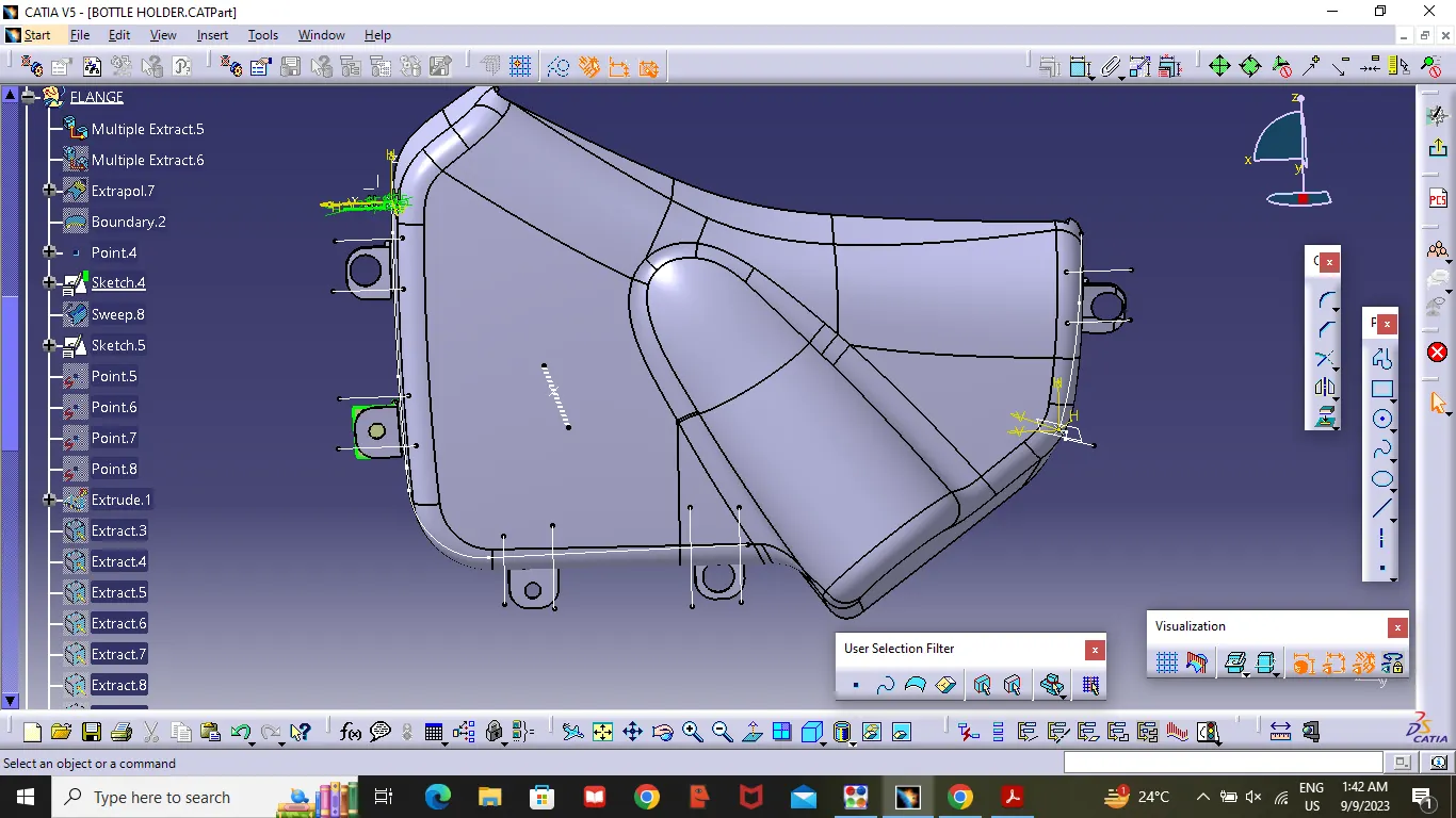
But for the Bottle holder there is no master section. by using previous components we created the flanges as showen in the figure .
Draft Analysis
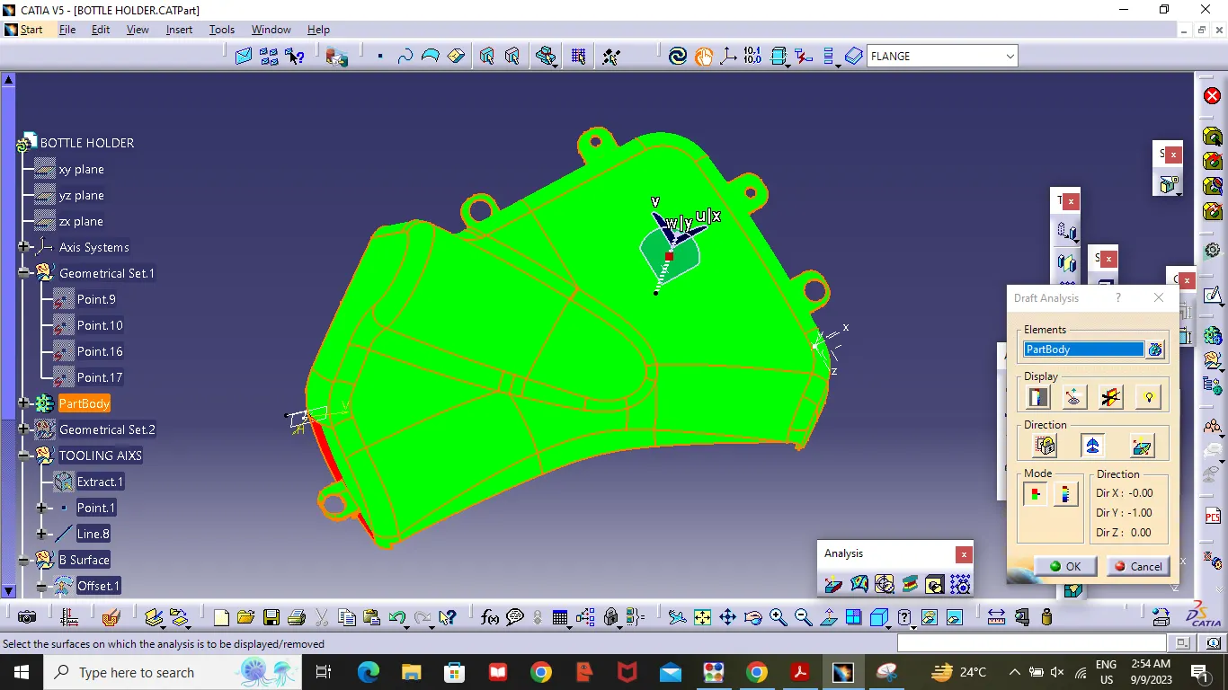
In Bottle Holder ,the Entire surfaces of the solid body cannot be able to clear the draft analysis in the solid body, because of the errors that spotted on the class A surface draft analysis, so we need to make a report including the errors that spotted on the solid body and submit to the respective team to alter then changes in the input surface to obtain a proper output .
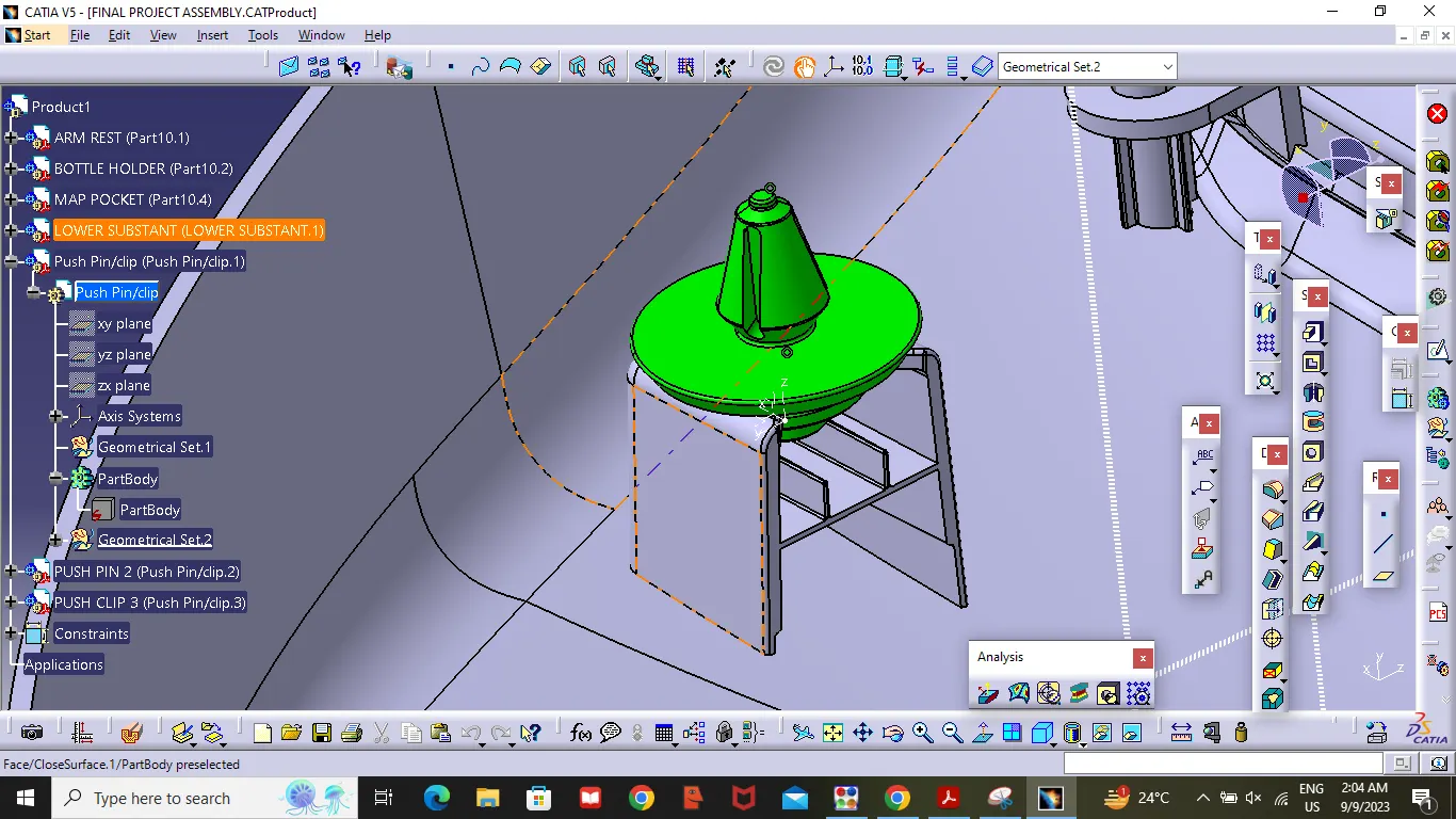
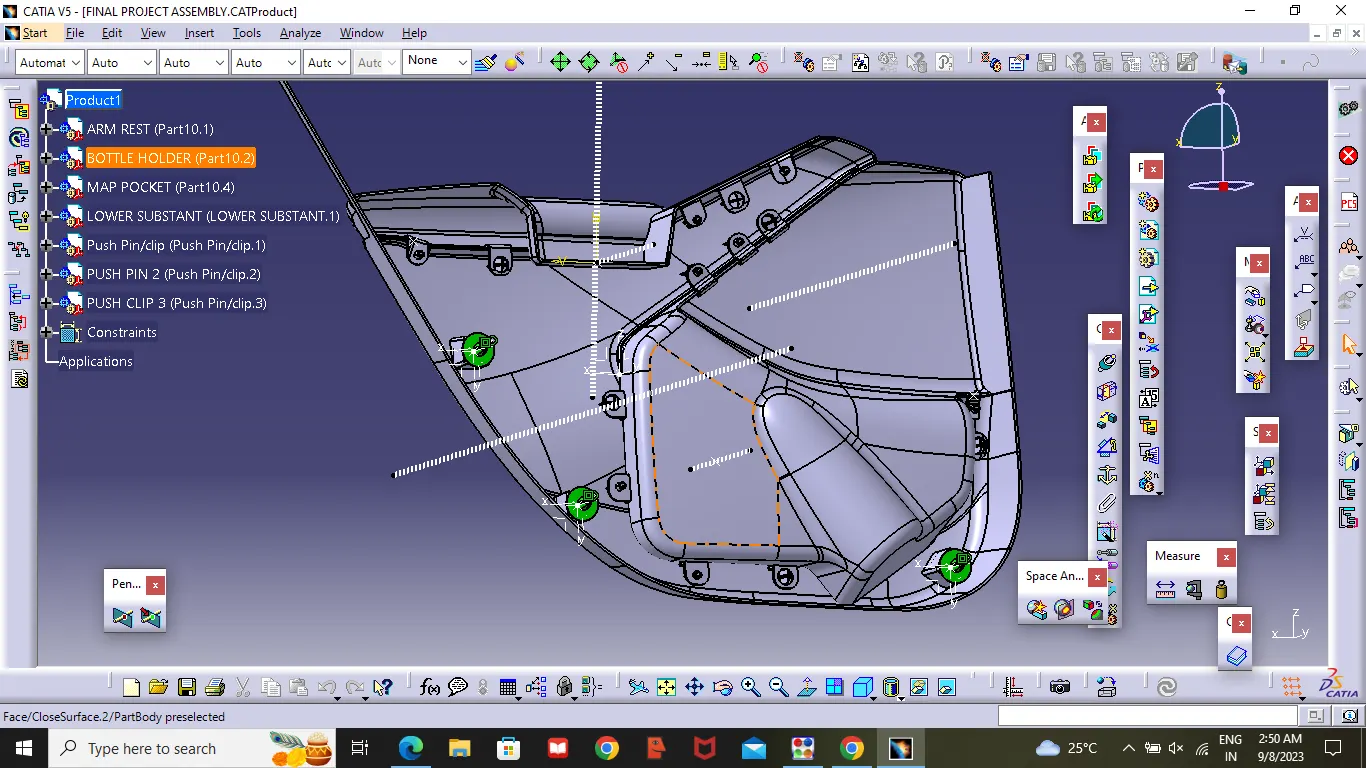
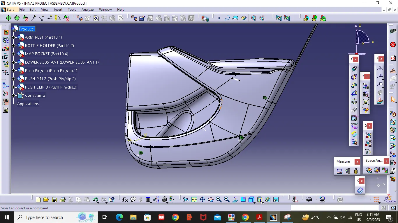
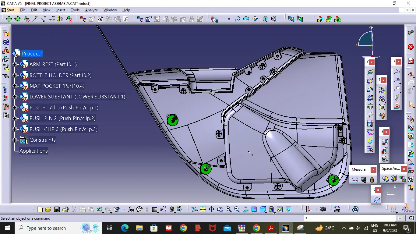
Assembly of Push pin
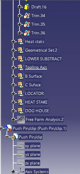
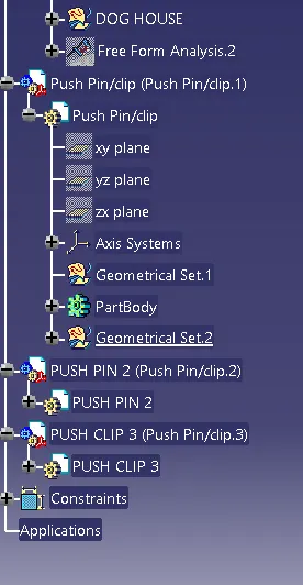
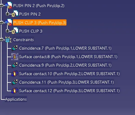
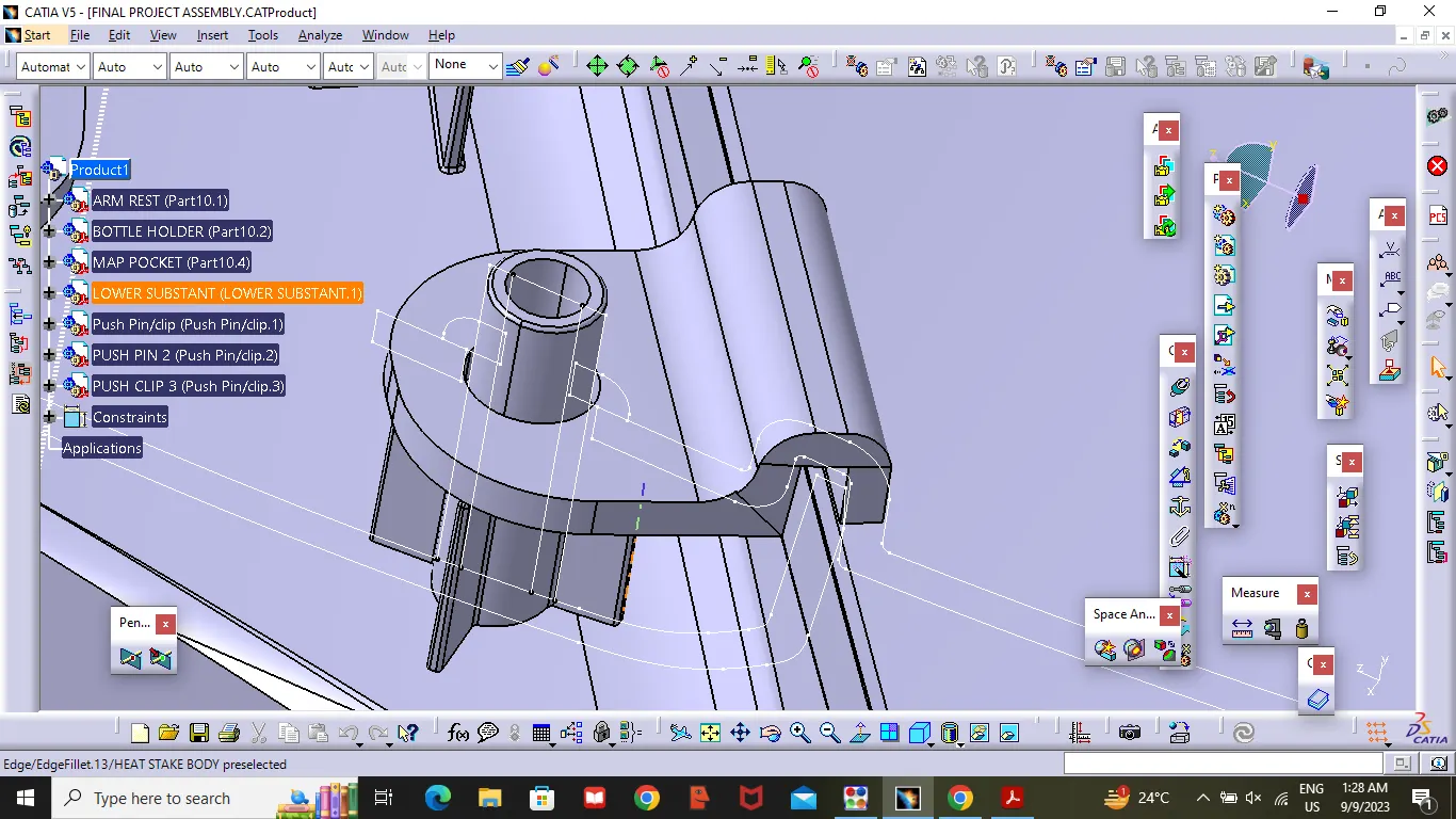
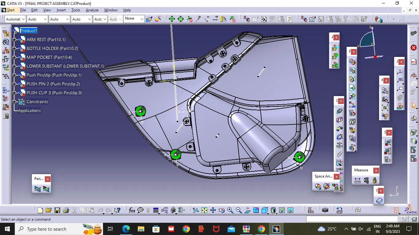
After Assemblying all the parts , now go to Exisiting component and insert the Push Pin after that by using Coincidence alline doghouse axis line to push pin axis line then update , now select contact constraint and select 3rd diameter surface of the push pin and select doghouse top panal then click update ,then it will get attached to the Doghouse .
Conclution:
Hence, the given Class A surface was successfully created as closed body with all the necessary attachement of Engineering Feature by following all the design rule .