Week 9 Challenge
AIM & INTRODUCTION:
To calculate the wave load on the bridge superstructure shown in fig. The maximum crest elevation for the wave is 3 m. The deck of the slab is supported by three I Girders. Each I Girder is 1.7 m height with a top and bottom flange width of 2.5m. The thickness of flange and web is 500 mmThe Span of the bridge is 12m. The width of deck slab is 9m and the thickness of deck slab is 2m. Assume constant r as 5. Assume Cva as 3. The Storm elevation is 8.5m. Take Cr as 0.4.
Wave Load:
*Waves are caused by a disturbance of the water surface.
*They develop due to disturbances like winds,boat, ship wakes or other forces such as underwater landslides due to earthquakes.
*When the wind blows on the sea , waves occur according to the intensity of the wind and generate a force on the any bridge substructure like piers and abutments.
*This accounted as wave loads in the design of substructure for designing bridges in the sea.
Given Data:
*Maximum Crest , ηmax=3m
*I Girder,
Top Flange=1.7m
Bottom Flange=2.5m
Thickness of Flange=0.5m
*Span of the bridge=12m
*Width of Span=9m
*Thickness of Deck Slab=2m.
*Assume constant Cr=0.4
*Assume Cva=3
*Storm Elevation=8.5m.
Calculations:
Δzh=ηmax-Centroid of I girder
=3-(3/2)
Δzh=1.5m.
Δzv=ηmax-Elevation of Bottom Deck
=3-2
Δzv=1m.
No.of Girders supporting Bridge deck,N=3
Vertical Loads, Fv=r*Δzv*Av
=5*1*(9*(1.7/2))
Vertical Loads, Fv=38.25KN
Horizontal Loads,Fh=r*Δzh*Ah
=5*1.5*(12*2)
Horizontal Loads,Fh =180KN
Max Vertical Loads,Fmax=Cva*Fv
=3*38.25
Max Vertical Loads,Fmax=114.75KN
Max Horizontal Loads,Fh=(1+Cr(N-1))*Cva*Fh
=[1+0.4*(3-1)]*3*180
Max Horizontal Loads,Fh=972KN.
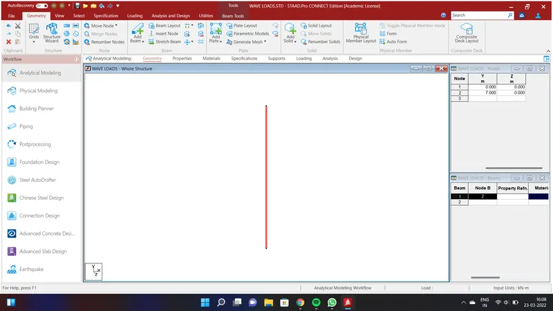
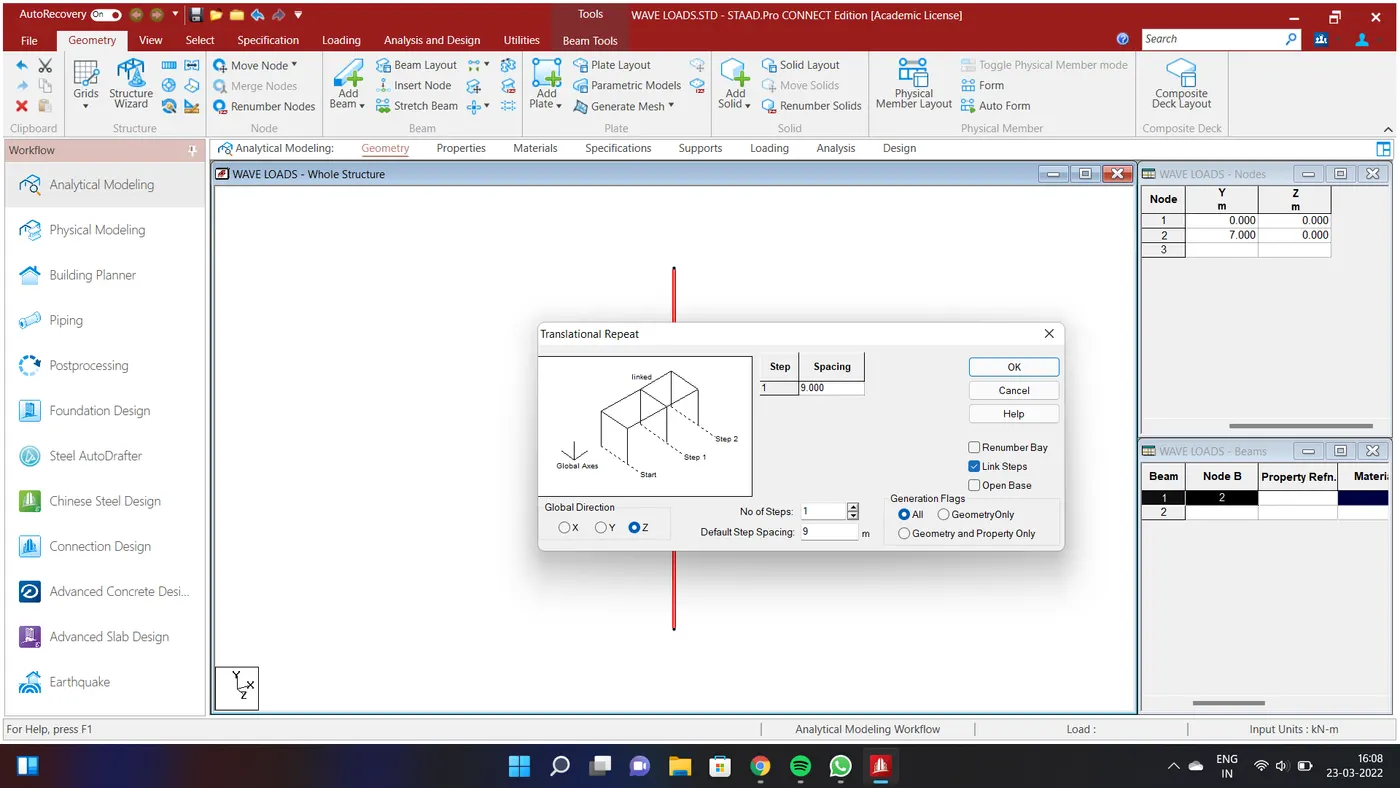
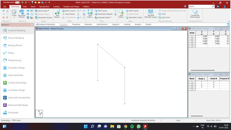
Create a node by assigning the values of Node1 as X=0;Y=0;Z=0. and Node 2=X=0;Y=7;Z=0. Connect the beams using Add beam in the Geometry Option. We will have created a pier of Height 7m. Select the beam and go to Geometry option and select the Translational Repeat in Global Z Direction by assigning the values as No.of Steps=1;Default Step Spacing=9m and click OK. Connect the two piers using Add Beam cursor so that we will have created a beams.
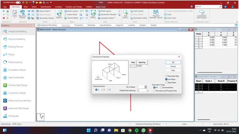
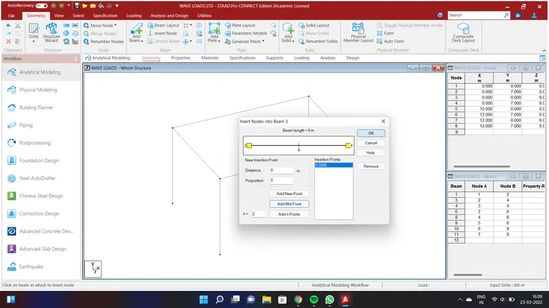
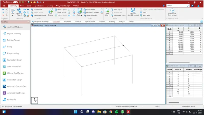
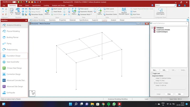
Select all the beams and go to Geometry option and select the Translational Repeat in Global X Direction by assigning the values as No.of Steps=1;Default Step Spacing=12m and click OK.in the Geometry option select the Insert node and select the Add Midpoint and click Ok.Connect the Beams at 4.5m along the width and 6m along the Length.
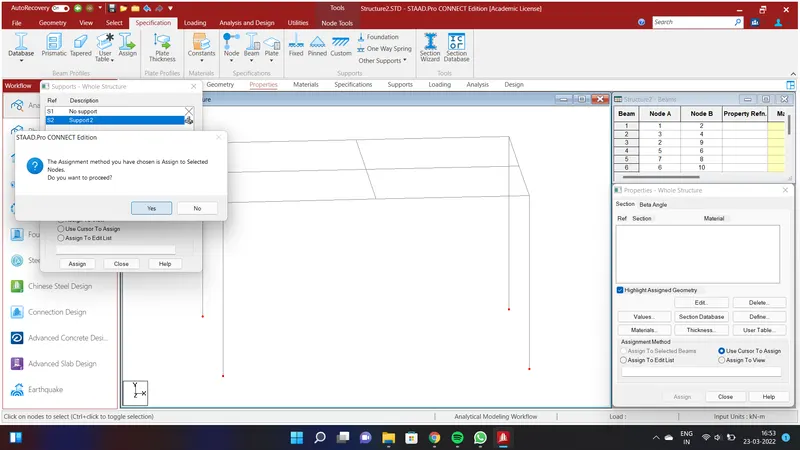
We shall assign fixed support to the bottom piers. To do that gp to Specification Option and select Fixed and Add and select support 2 and click add. Go to node cursor in the select all the nodes at the bottom of the piers and Click Assign to Selected Beams and clcik Assign and click YES.
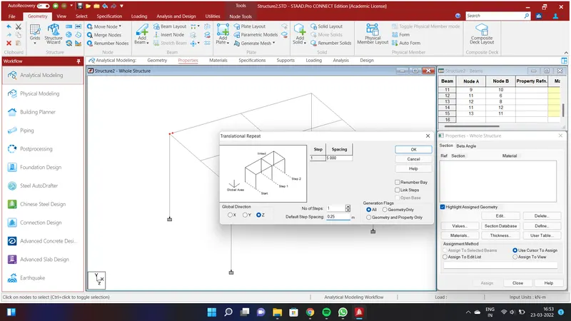
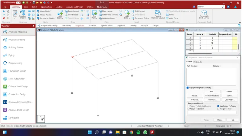
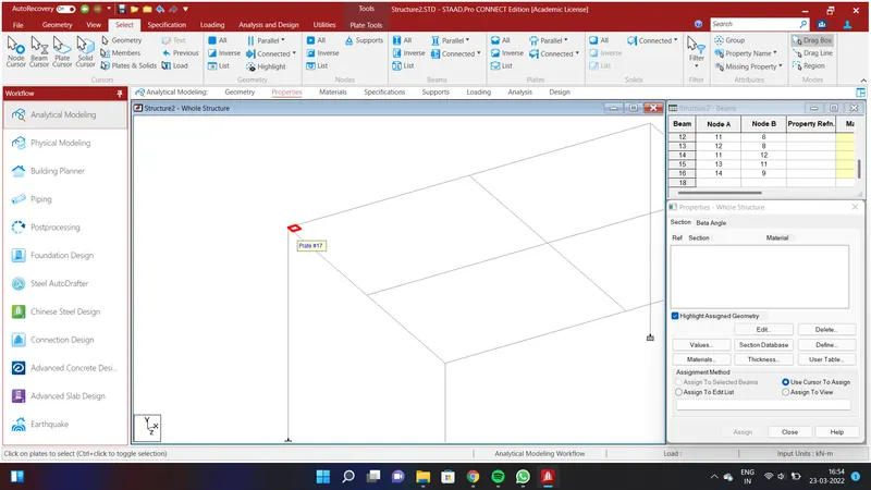
We will create a Deck Slab. Go to Geometry Option and select the Translational Repeat in Global Z Direction by assigning the values as No.of Steps=1;Default Step Spacing=0.25m and click OK.Again select the nodes and go to Geometry Option and select the Translational Repeat in Global X Direction by assigning the values as No.of Steps=1;Default Step Spacing=0.25m and click OK.Select the Add plate and select the four nodes and go to select option and select Plate option.We will have created a plate.
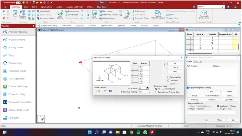
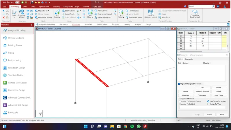
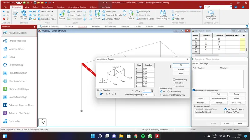
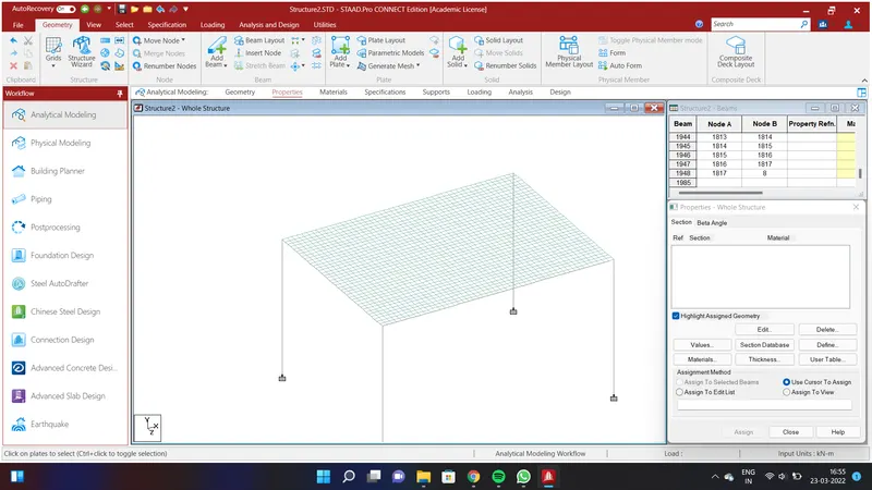
Again select the plates and go to Geometry Option and select the Translational Repeat in Global Z Direction by assigning the values as No.of Steps=35;Default Step Spacing=0.25m and click OK.Again select the plates and go to Geometry Option and select the Translational Repeat in Global X Direction by assigning the values as No.of Steps=47;Default Step Spacing=0.25m and click OK.We will have created a Deck slab throughout the beam.
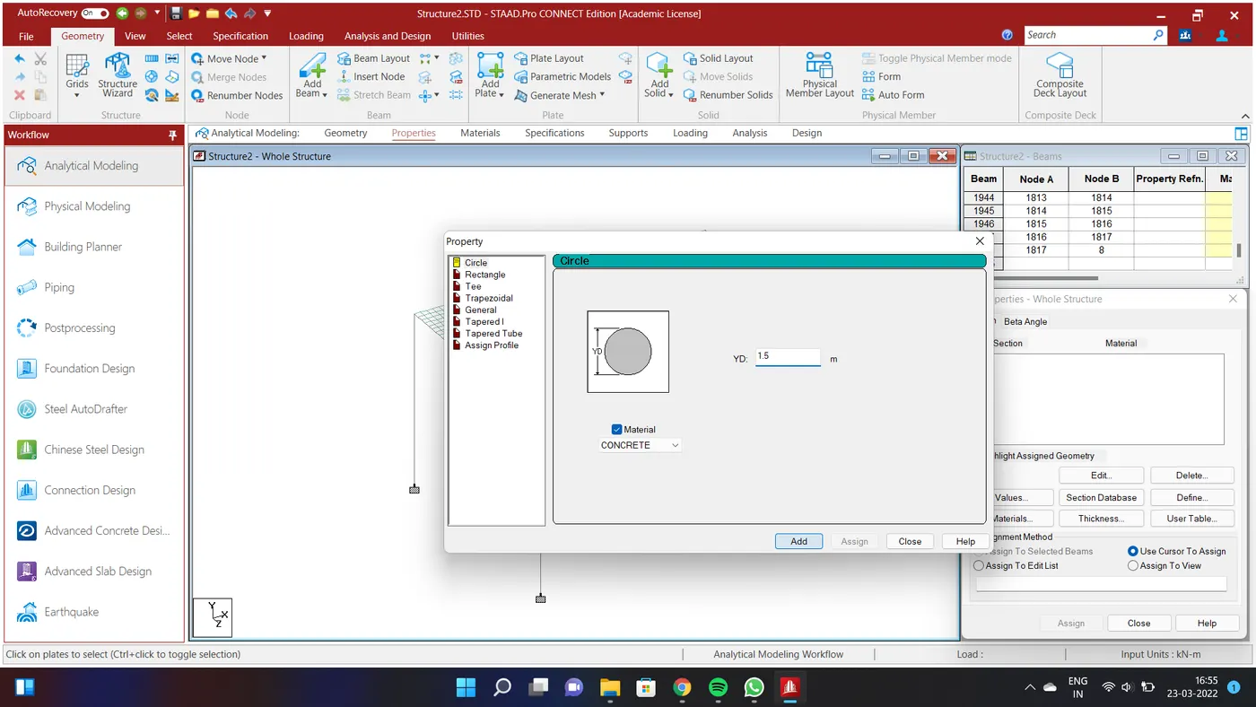
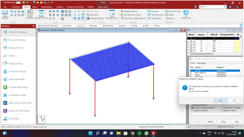
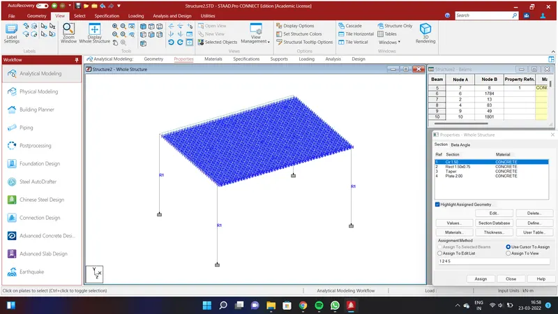
Go to Geometry option and select Specification Option and select Prismatic and go to circle and assign the values of YD=1.5m using Concrete Material and Add.Click Assign to Selected Beams and click Assign and click YES.
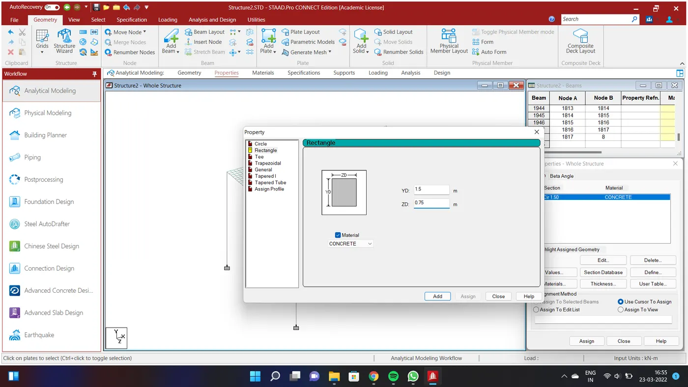
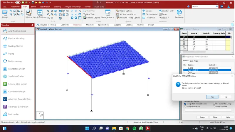
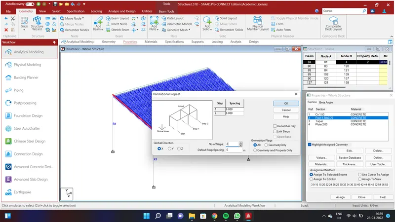
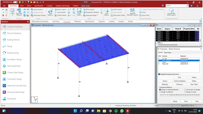
We shall assign properties to cross girders .Go to Geometry option and select Specification Option and select Prismatic and go to circle and assign the values of YD=1.5m;ZD=0.75m using Concrete Material and Add.Click Assign to Selected Beams and click Assign and click YES.Again select the cross girders and Go to Geometry Option and select the Translational Repeat in Global X Direction by assigning the values as No.of Steps=2;Default Step Spacing=6m and click OK.We shall have provided properties to the cross girders.
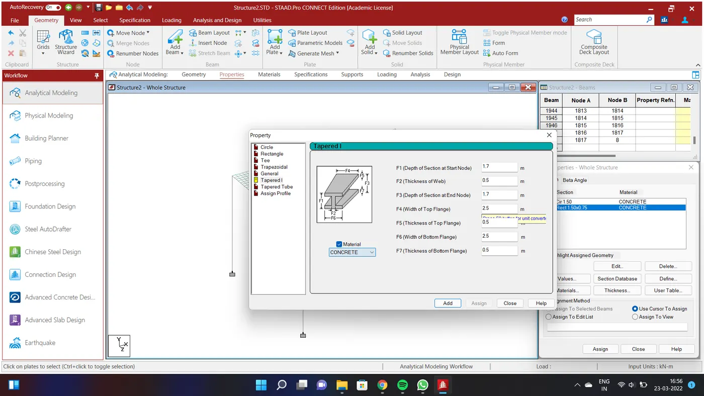
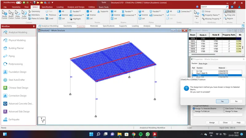
We shall assign properties to girders .Go to Geometry option and select Specification Option and select Prismatic and go to Tapered I and assign the values of F1=1.7m;F2=0.5m;F3=1.7m;F4=2.5m;F5=0.5m;F6=2.5m;F7=0.5m using Concrete Material and Add.Click Assign to Selected Beams and click Assign and click YES..We shall have provided properties to the girders.
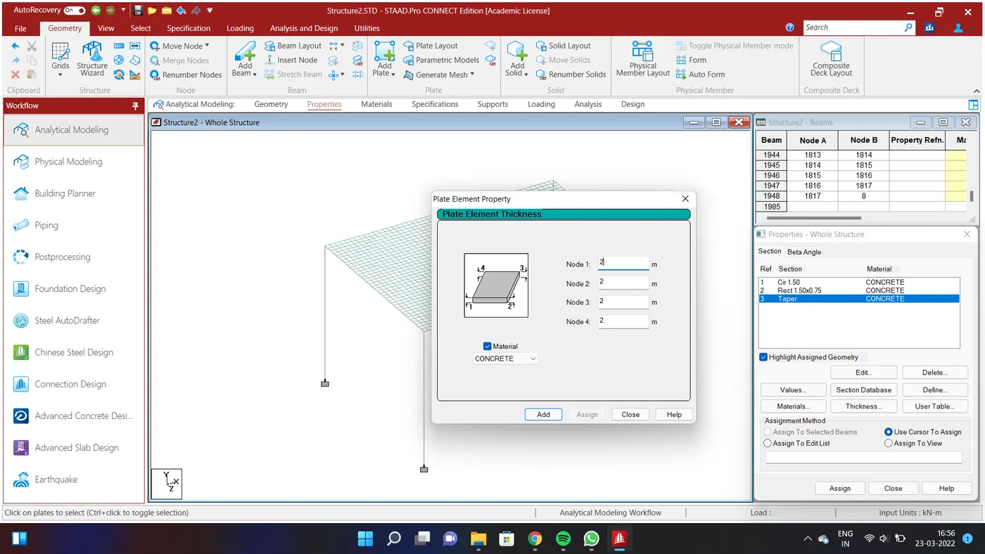
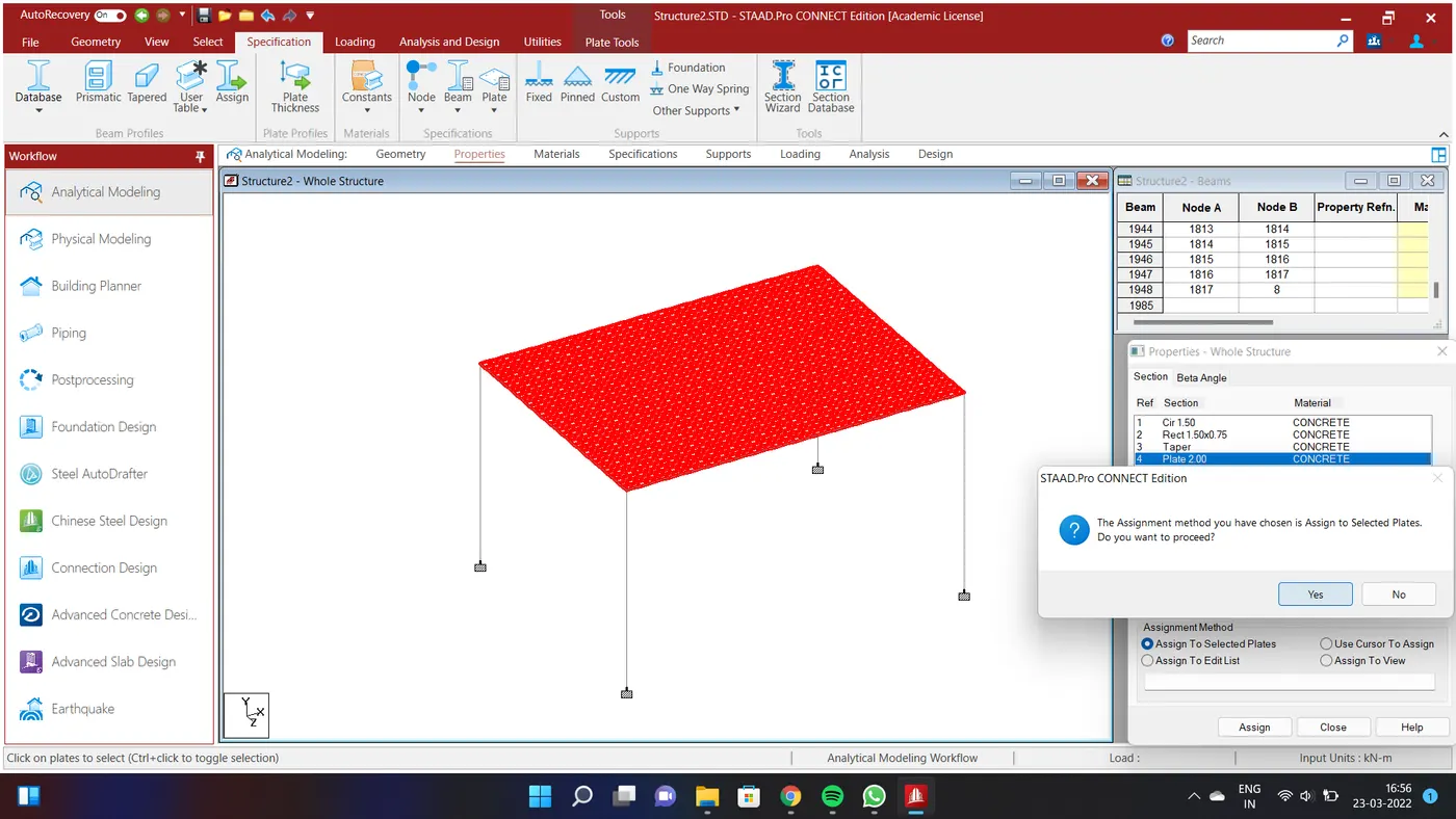
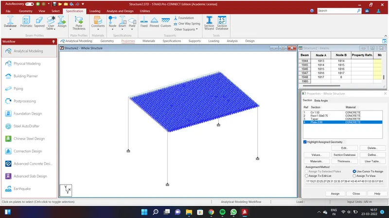
Go to Geometry option and select Specification Option and give the Deck Slab thickness as 2m and click Assign to Selected Plates and click Assign and click YES.
RESULT:
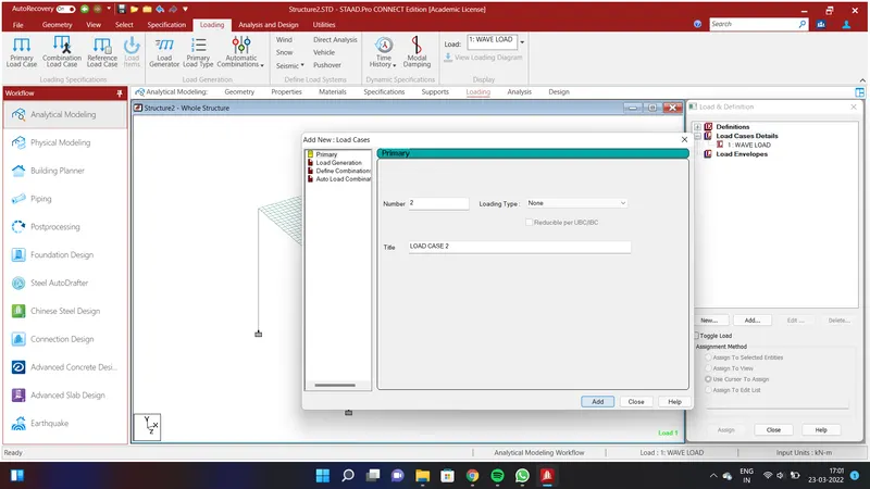
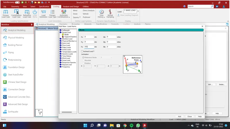
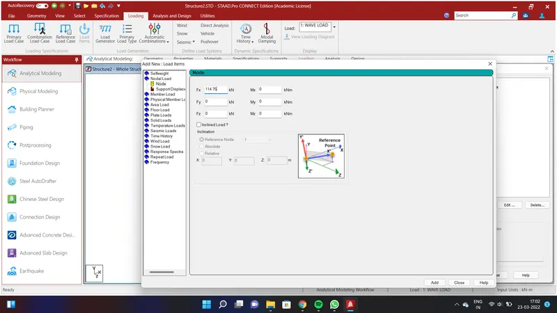
After assigning all the properties to the structure we shall apply the loading. Go to loading option and select Load Case Details and click Add . Give the title as WAVE LOAD and click add. Select the WAVE LOAD option and go to Nodal Load anf give the value Fx=0;Fy=0;Fz=972KN.
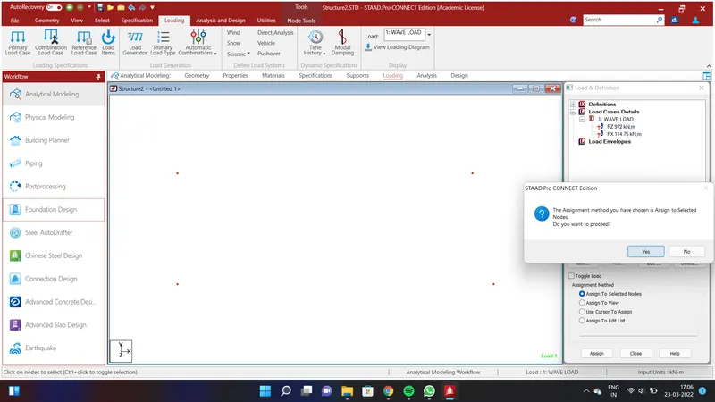
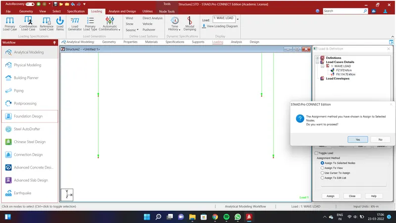
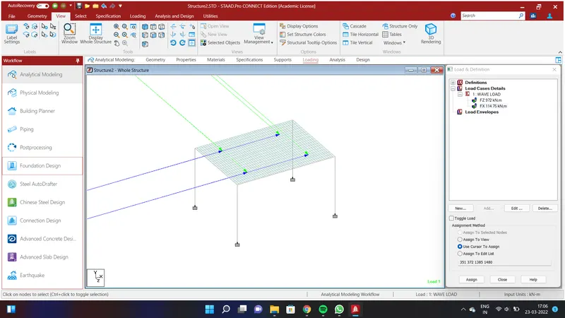
Go to select option and select node cursor and select the node at 4.5m along cross girder and 6m along the girder .Keep the centre node and select. So similarly throughout the bridge and apply the load Fz=972KN and click Assign to Selected nodes and Assign and YES. Again select the nodes and apply the load Fx=114.75KN and click Assign to Selected nodes and Assign and YES.
REPORT:
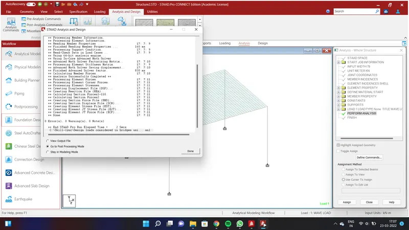
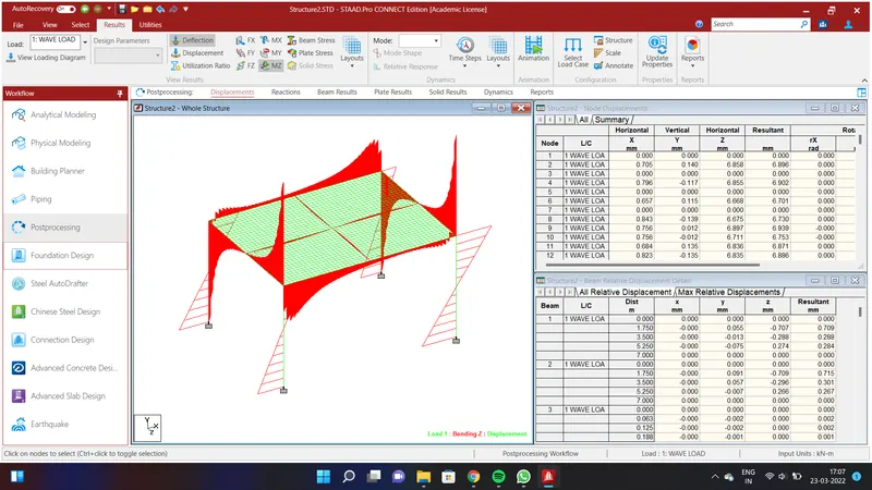
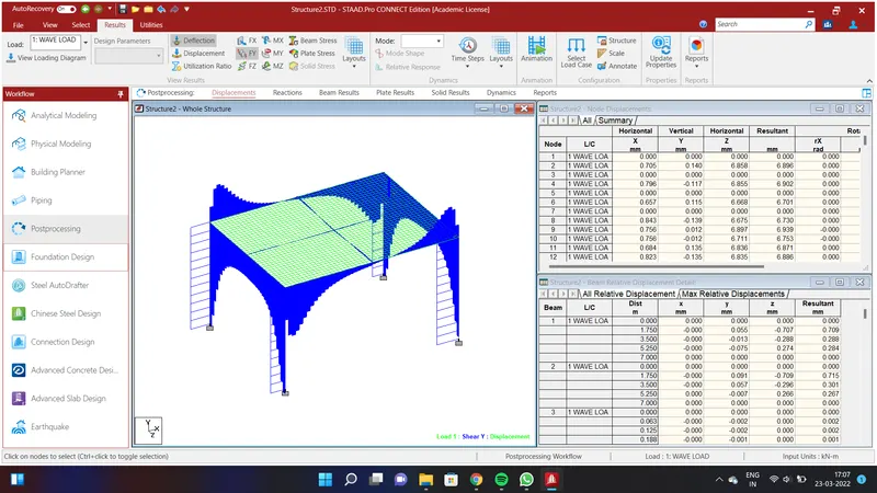
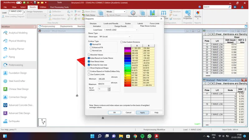
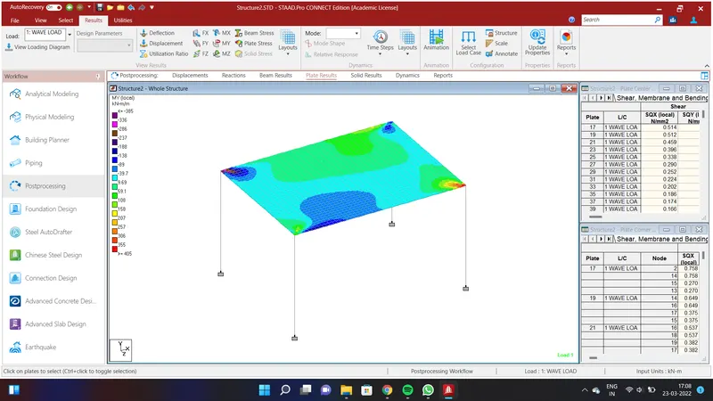
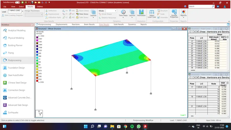
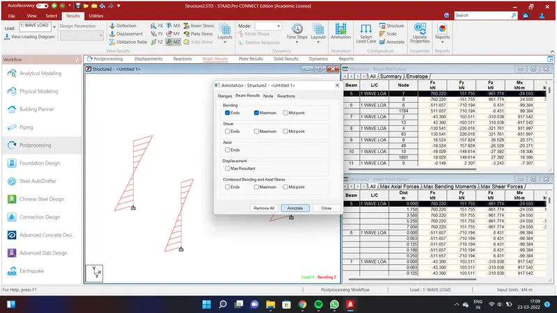
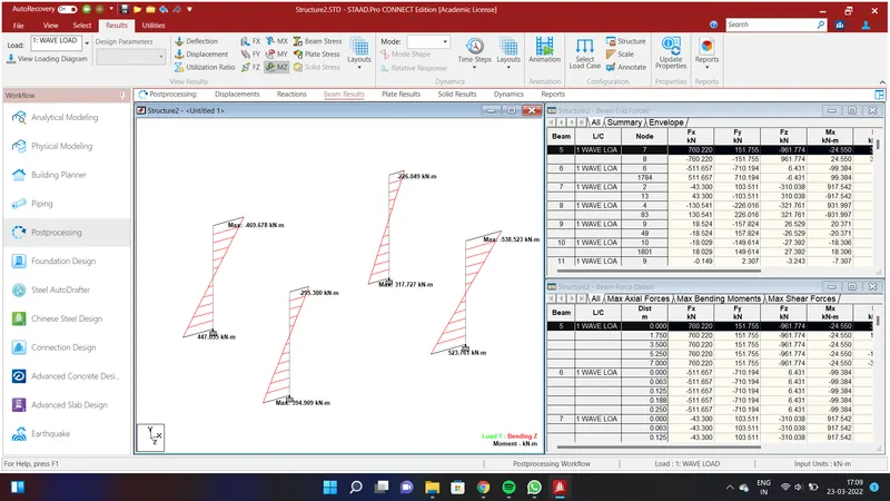
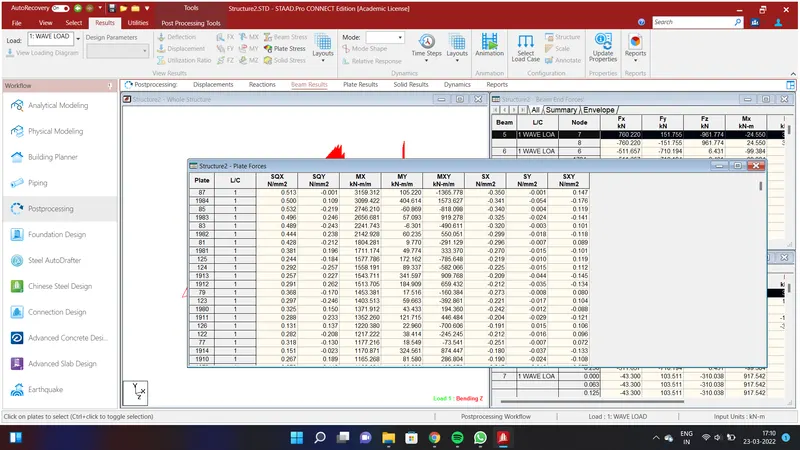
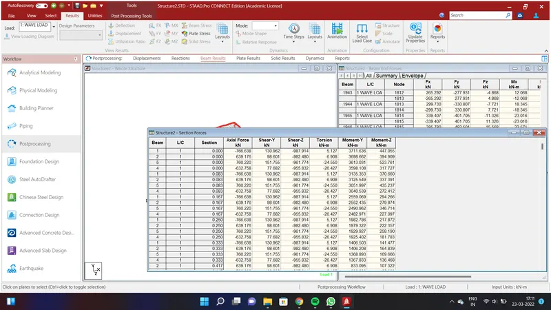
We have obtained the plate results and beam results of the following WAVE LOAD.