Week 3 Challenge
AIM & INTRODUCTION:
To design the I Girder Bridge and Apply the IRS live loads and model in Staad pro and perform the structural analysis.
The live load on the bridge, is moving load on the bridge throughout its length. The moving loads are vehicles, Pedestrians etc. but it is difficult to select one vehicle or a group of vehicles to design a safe bridge.
GIVEN DATA:
*Width of Bridge Deck=26m.
*Span of thr Bridge=25m.
*Height of the Pier=10m.
PROCEDURE:
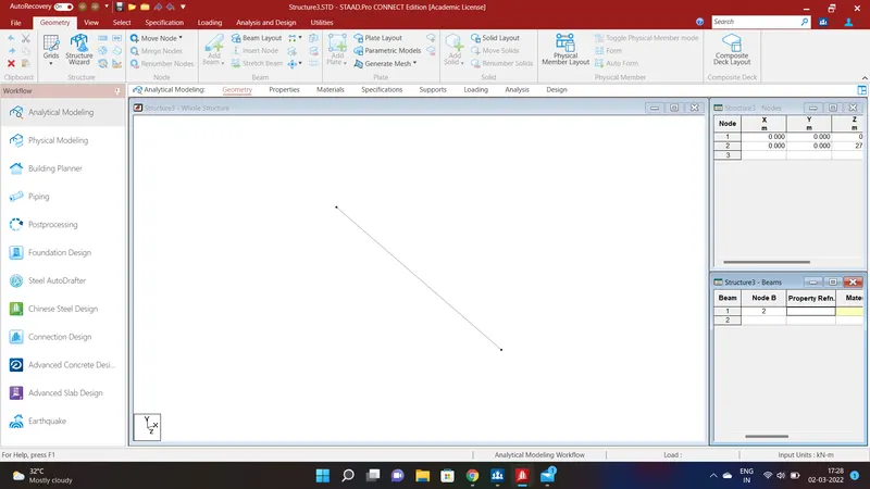
The width of the beam is taken as 28m. in XZ coordinates. To do so in STAAD Pro we have to go to the Geometry option and gives length of nodes in XZ direction and select the two nodes using add beam cursor and connect the two nodes and the width is created.
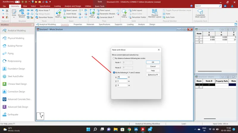
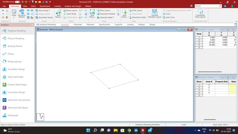
To crete another pier for a span of 25m in STAAD Pro click ctrl C and ctrl V , a box will appear. We should assign values as X=25m;Y=0;Z=0 and click OK . We shall have created another Span with a width of 28m in the X direction. Now go to Geometry and add beam and join all the beams and we shall have created all the width and span of the beams.
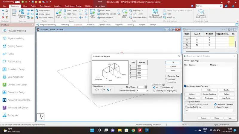
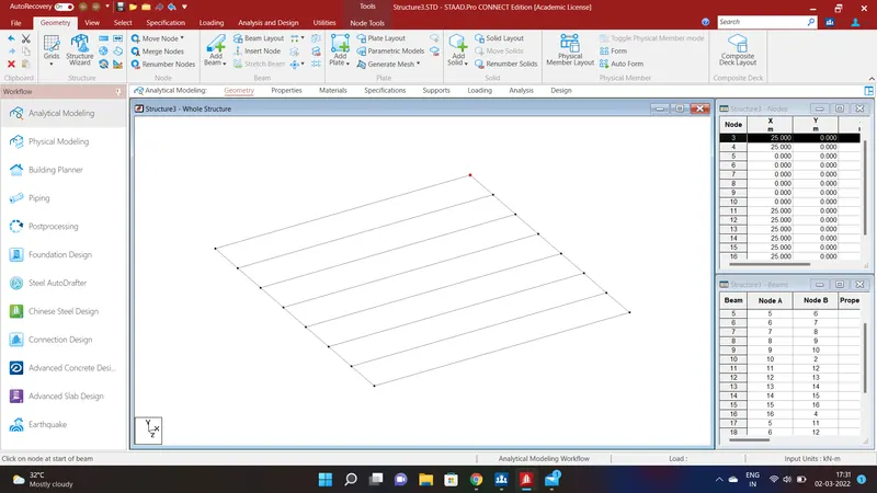
In the given question we should create girder along the X direction . To do so select the node cursor and select the beam and go to Geometry option and go to Translational Repeat in Z direction and assign the No. of Steps=6;Default Step Spacing=4m. Continue the same on the other side of the Beam and by using the Add beam cursor Join the the two nodes.
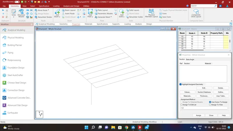
Again the select the node by using node cursor option at the 24m node and go to Geometry option and select Translational Repeat in Y direction and assign the No. of Steps=1;Default Step Spacing=-10m and link steps a Pier of Height 10m is built.
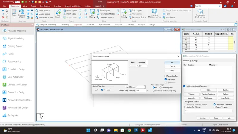
Again the select the node by using node cursor option at the 4m node and go to Geometry option and select Translational Repeat in Y direction and assign the No. of Steps=1;Default Step Spacing=-10m and link steps a Pier of Height 10m is built.
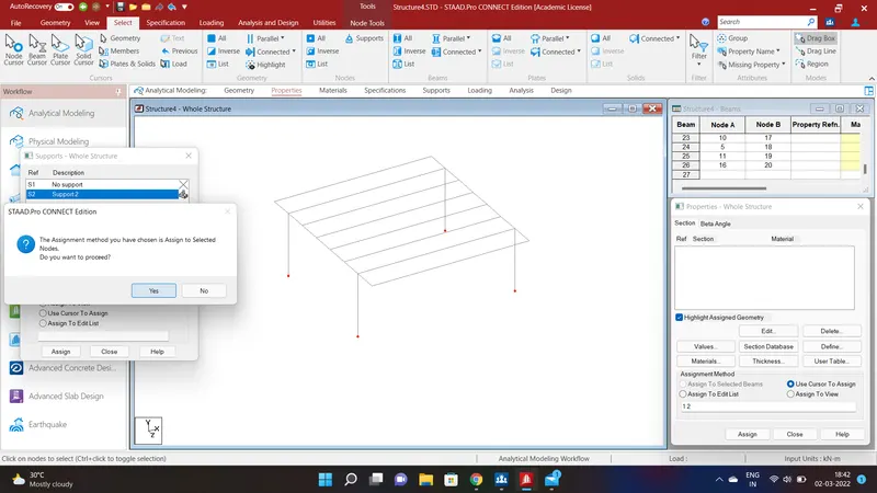
Again the select the node by using node cursor option at the 4m and 24m on the other side of the beam and go to Geometry option and select Translational Repeat in Y direction and assign the No. of Steps=1;Default Step Spacing=-10m and link steps a Pier of Height 10m is built. Now the piers are created and the girders are also designed in the STAAD Pro.
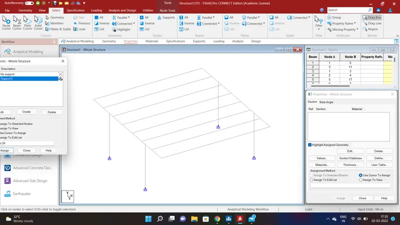
To assign fixed support to the piers go to the specification option and go to Fixed and Add the properties of the suppoer 2. Now select the node cursor from the select option and select all the pier end nodes and assign to selected Beams and assign and click YES.Now the Fixed support is created to the piers.
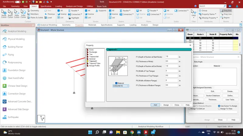
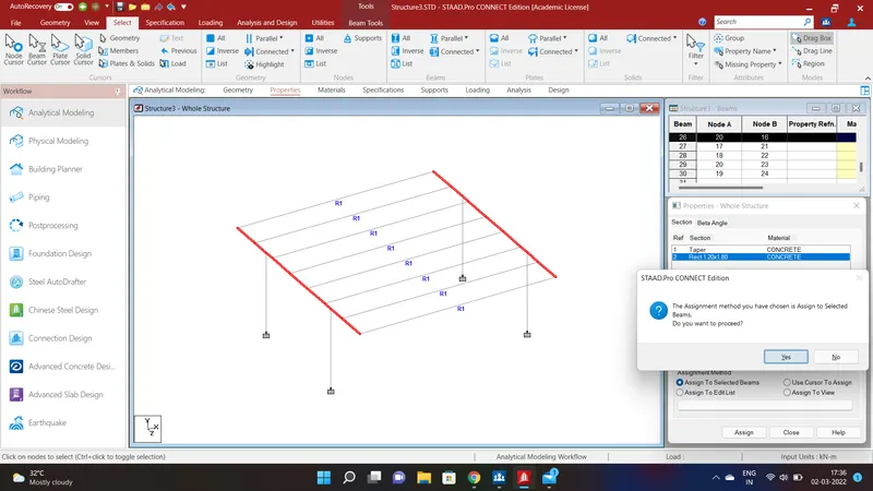
Now we have assign properties to the Beams ,Girders and Pier. Since anything is not mentioned in the given problem we can assign the propertios of the Beams ,Girders and Pier by assuming the apporpriate values. Select all the Girders and go to the specification option and Prismatic and select the Tapered I and assign the values as Follows F1=1.8 m;F2=0.5m;F3=1.8m;F4=2m;F5=0.5m;F6=2m;F7=0.5m and select the concrete material and ADD.
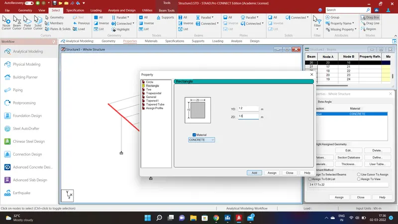
Then select all the cross Girders and go to user data and select define . in the screen select the rectangale section and add the values of YD=1.2m;ZD=1.8m using Concrete material. After that select the Beams and assign to selected beams and assign. Then click Yes.
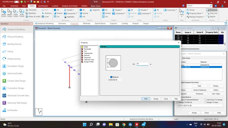
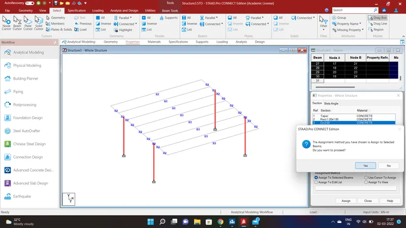
Then select all the piers and go to user data and select define . in the screen select the rectangale section and add the values of YD=2.5 using Concrete material. After that select the piers and assign to selected beams and assign. Then click Yes.
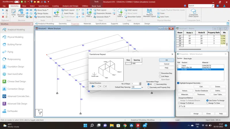
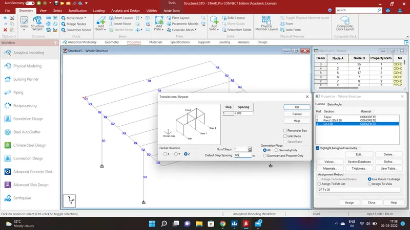
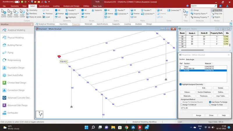
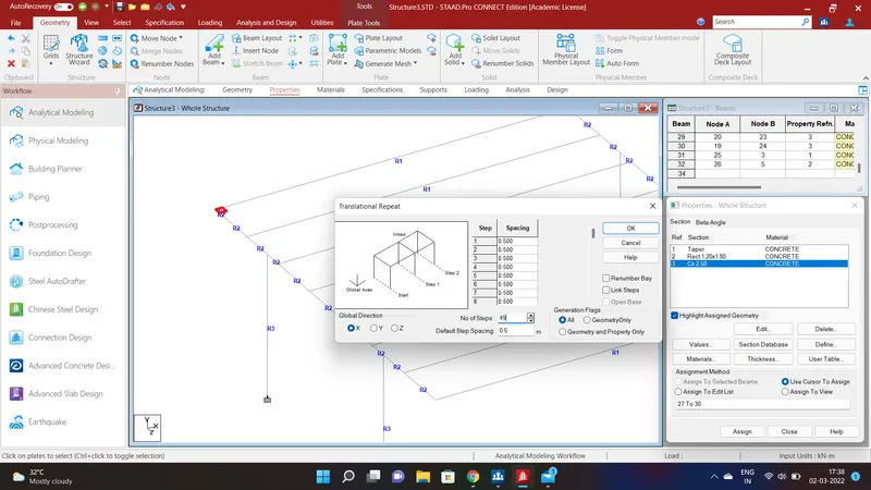

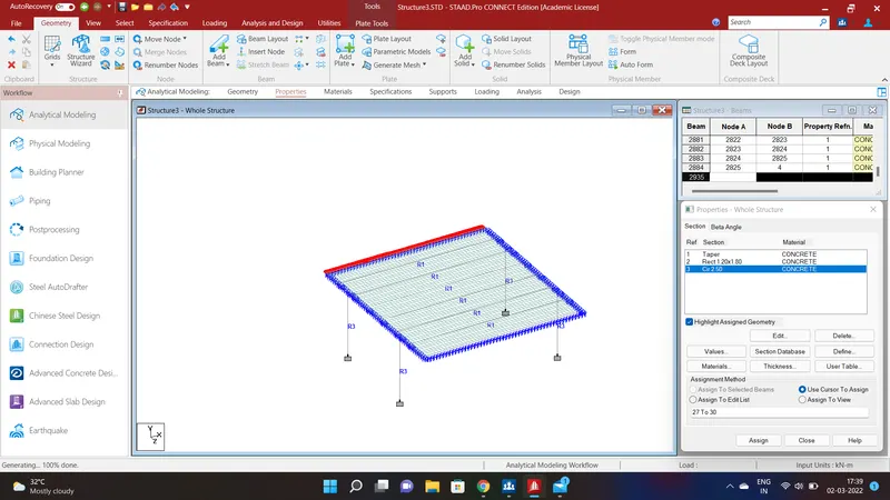
Select the node cursor and select the first pier on th beam and go to Geometry option and go to Translational Repeat in Z direction and assign the No. of Steps=1;Default Step Spacing=0.5m. Again Select the node cursor and select the first pier on th beam and go to Geometry option and go to Translational Repeat in X direction and assign the No. of Steps=1;Default Step Spacing=0.5m. A box will be made using the plate beam and a plate is applies using the plate cursor. Select the plate and go to Geometry option and go to Translational Repeat in X direction and assign the No. of Steps=49;Default Step Spacing=0.5m. Now copy all the plates and go to Geometry option and go to Translational Repeat in Z direction and assign the No. of Steps=55;Default Step Spacing=0.5m. We will have created all the plates.
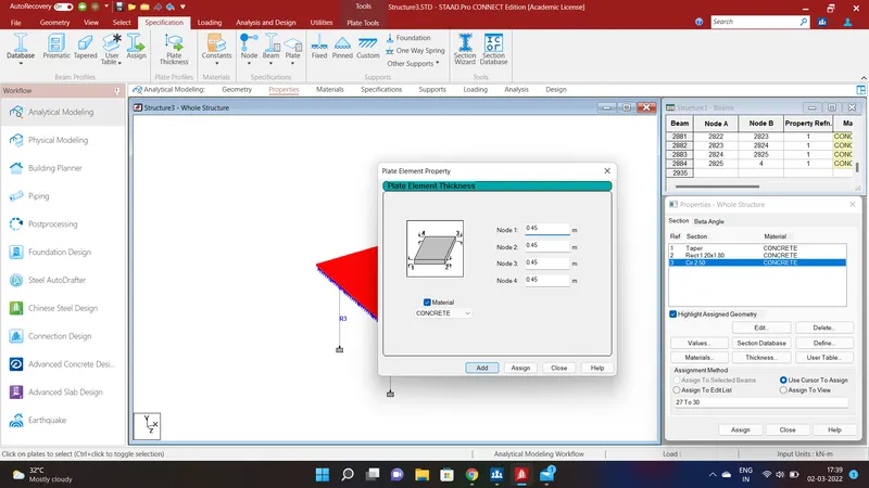
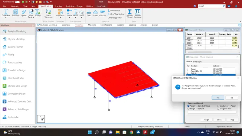
To assign values for the plates go for the Specifications Options and select the Plate Thickness and give values as Node 1=0.45m;Node 2=0.45m;Node 3=0.45m;Node 4=0.45m. using Concrete material. After that select the Beams and assign to selected beams and assign. Then click Yes.
RESULTS:
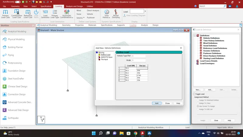
To obtain results we need assign the live loads to the structure. In order to do so we should go to the Loading menu and go to Definition and select Vehicle Definition. Click add and define load. Mention the width as 1. Add the Electric Train loading as mentioned in IRS code. and click Add.
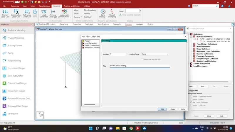
 .
.
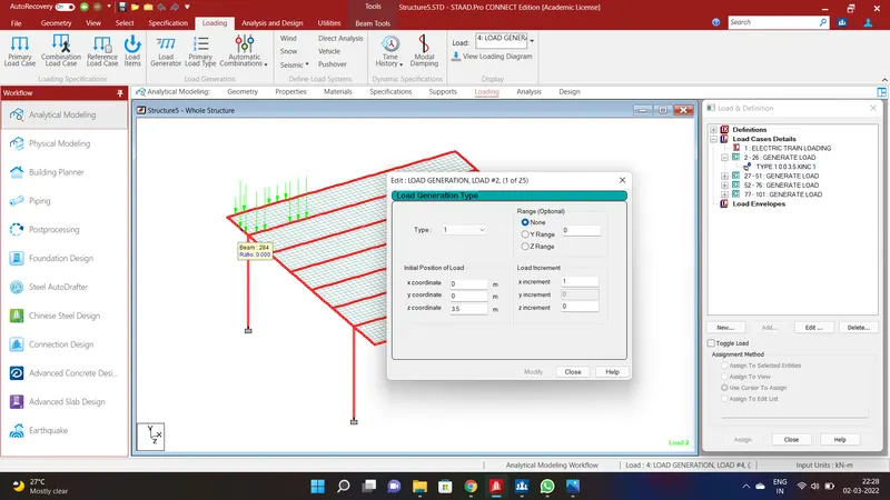

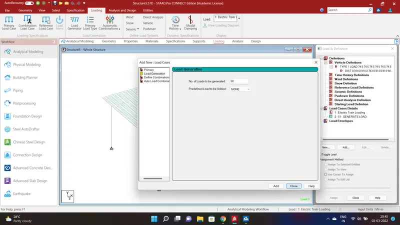
Since it is four lane bridge we have to assign the load in 4 points . To do so select the Load Case Details and click Add and go to load Generation and add the No. of Loads to be Generated as 25 and add. We should apply the load at the specific point on the slab. To do that go to Load Generation Type and select Initail Portion of Load and give following values as X=0;Y=0;Z=3.5m and Load Increment as 1 in X Increment Electric Train loading. Do the same for the other load and give following values as X=0;Y=0;Z=8.5m and Load Increment as 1 in X Increment Electric Train loading.
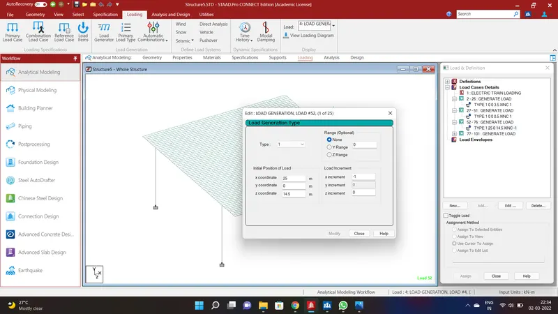
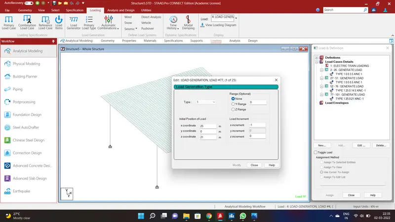
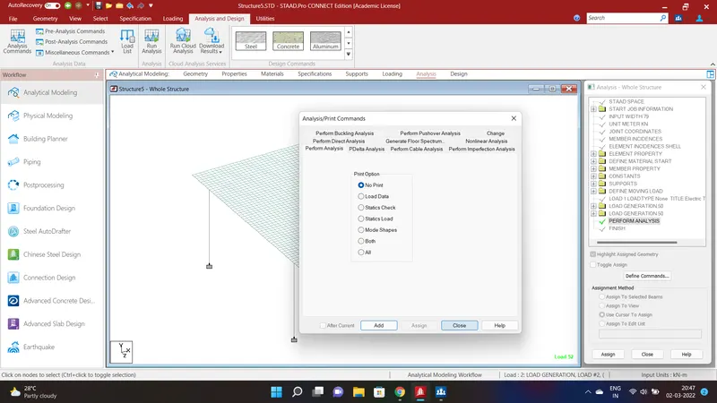
Select the Load Case Details and click Add and go to load Generation and add the No. of Loads to be Generated as 25 and add. We should apply the load at the specific point on the slab. To do that go to Load Generation Type and select Initail Portion of Load and give following values as X=25m;Y=0;Z=14.5m and Load Increment as -1 in X Increment. for Electric Train loading. Do the same for the other load and give following values as X=25m;Y=0;Z=21m and Load Increment as -1 in X Increment Electric Train loading. After assign the Loads Go to analysis and Design Command and select the Analysis Command and Perform Analysis. Then go to Run analysis and go to the Post Processing Mode. IN the Post Processing Mode we can obtain the Required Results.
REPORT:
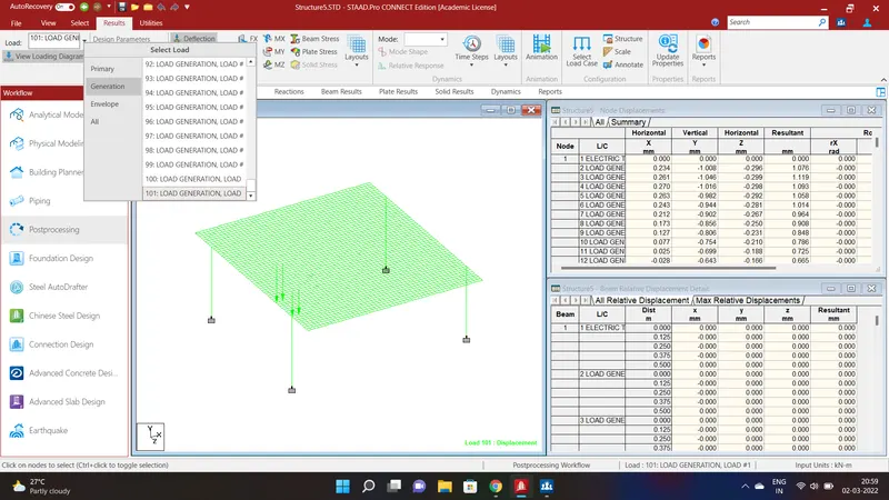
Loada at different points in the lane which we have acquired from the view loading Diagram.
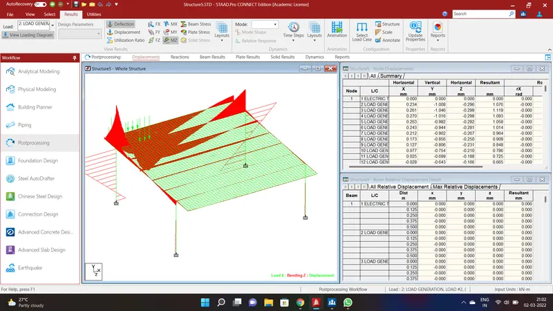
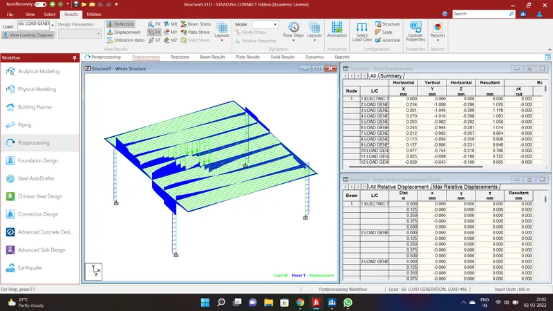
When moment is applied in the X direction and shear force at Y direction.
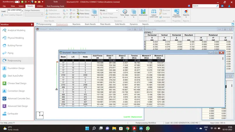
Beam End Forces is obtained by selecting all the beamd using beam cursor and gp to results and select the beam end forces and the moment at Y direction and we can obtain the max.moment at Y .To obtain the results at Z Direction go to results and select the Beam End Forces and the moment at Z direction and we can obtain the max.moment at Z.
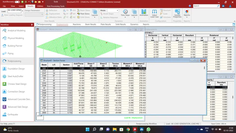
Section Forces is obtained by selecting all the beam using beam cursor and go to results and select the Section Forces and the moment at Y direction and we can obtain the max.moment at Y. To obtain the results at Z Direction go to results and select the section Forces and the moment at Z direction and we can obtain the max.moment at Z.
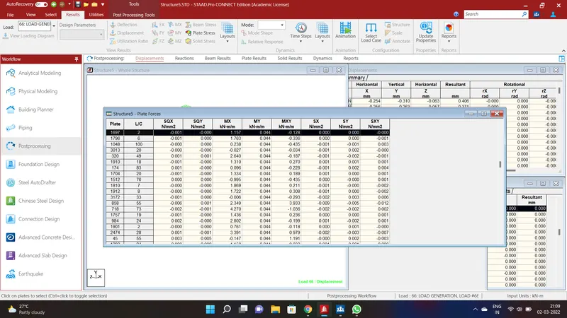
To obtain Plate Results select all the plates using plate cursor using select option go to results and select the Plate Stresses and the moment at Y direction and we can obtain the max.moment at Y. To obtain the results at Z Direction go to results and select the Plate Stresses and the moment at Z direction and we can obtain the max.moment at Z.
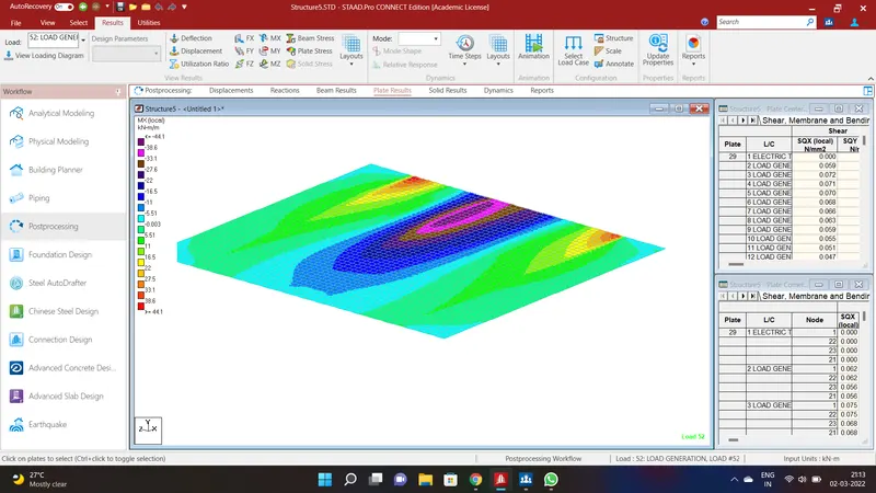
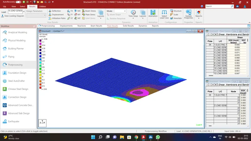
Max moment obtained on the plates in the bridge is 44.1 in MX(LOCAL) & 24.6 in MY(LOCAL).
The results are generated in STAAD Pro and the Beam stresses and loads are obtained. The result obtained are as follows
* Beam End Forces - Moment at Z
* Beam End Forces - Shaer at Y
* Section Forces- Moment at Z
* Section Forces - Shaer at Y
Plate Forces;
* Plate Stresses.