Week 5 Challenge
AIM AND INTRODUCTION:
To calculate the design wind loads for the bridges to be designed at Mumbai.
GIVEN DATA:
- The height of the bridge above ground level is 9 m.
- It is located in open terrain with well scattered obstructions of height less than 10m.
- The pier size is 1.5 x 1.5 m.
- Apply the wind load in Staad.pro.
WIND LOAD:
Wind load is the load, in pounds per square foot, placed on the exterior of a structure by wind. This will depend on: The angle at which the wind strikes the structure. The shape of the structure (height, width, etc.)
PROCEDURE:
To calculate wind pressure;
Wind Speed=Vz=Vb*K1*K2*K3*K4
Basic Wind Speed,Vb=44m/s(From IS 875 PART III 2015)for the region in Mumbai.
- FACTOR K1;
Referring Table 1 of IS 875 PART III 2015, For important structure and wind speed 44m/s, the K1=1.07.
- FACTOR K2;
Referring Table 2 of IS 875 PART III 2015, For height 9m and category 2 structure K2=1.00.
- FACTOR K3;
As per Cl 6.3.3 IS 875 PART III 2015 for upward wind slope les than 3 Degree Factor, K3=1.00.
- FACTOR K4;
When the location is within 60KM radius of the ocean, the cyclone factor is taken in to account K4=1.3
DESIGN WIND SPEED Vz=Vb*K1*K2*K3*K4
=44*1.07*1.00*1.00*1.3
=61.204m/s
WIND PRESSURE=0.6*Vz^2
=0.6*(61.204)^2
WIND PRESSURE =2.247KN/m^2.
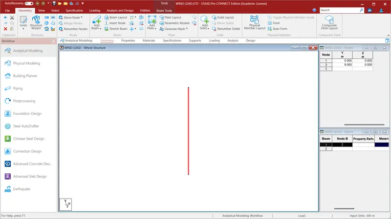
Create a pier of height 9m in Staad Pro. To to do that give the values of Node 1 as X=0;Y=0;Z=0 and Node 2 as X=0;Y=9m;Z=0 . Two node will be created seperated by a distance of 9m . Go to geometry and select Add Beam and join the two nodes.A pier is created for a height of 9m.
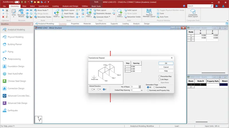
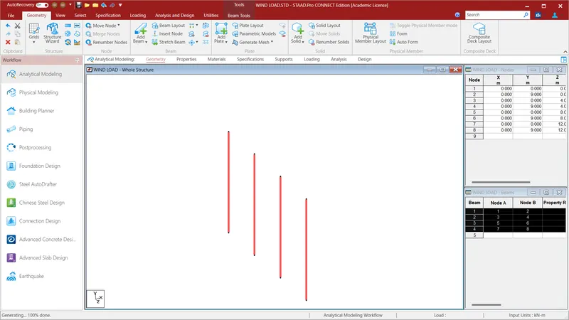
Now go to the select option and select the beam cursor and select the beam and go to Geometry and go to Translational Repeat and click the Global Z Direction and assign the values as follows No. of Steps=3;Default Step Spacing=4m and click OK. Totally four piers of height 9m seperated by a distance of 4m will be created.
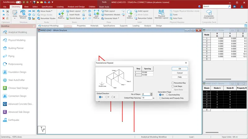
Select the beam cursor and select all the beam and go to Geometry and go to Translational Repeat and click the Global Y Direction and assign the values as follows No. of Steps=2;Default Step Spacing=10m and click OK.
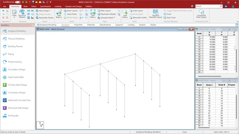
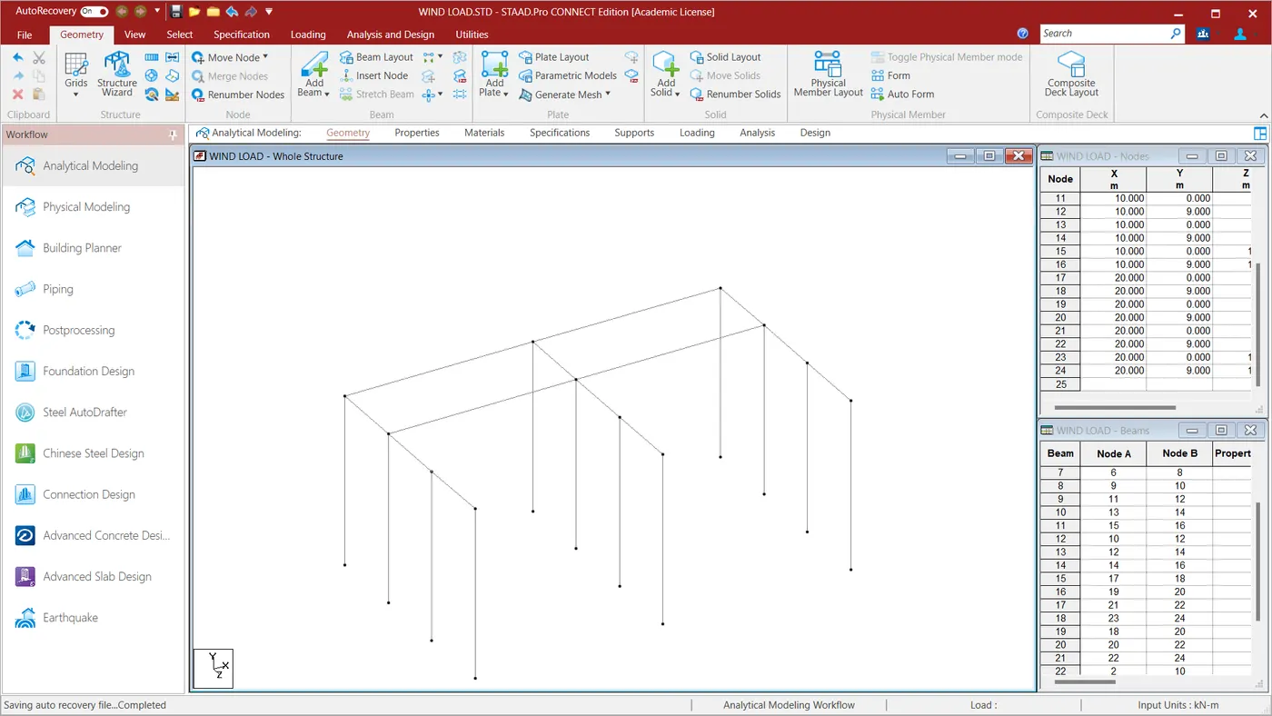
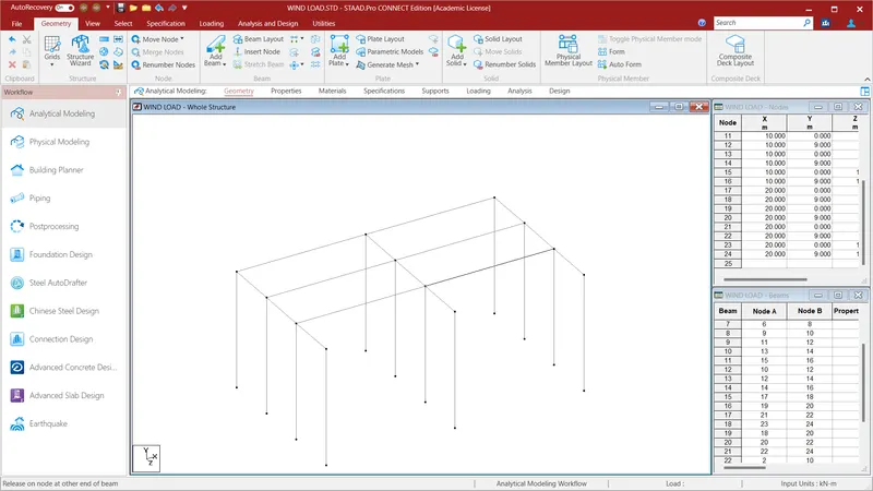
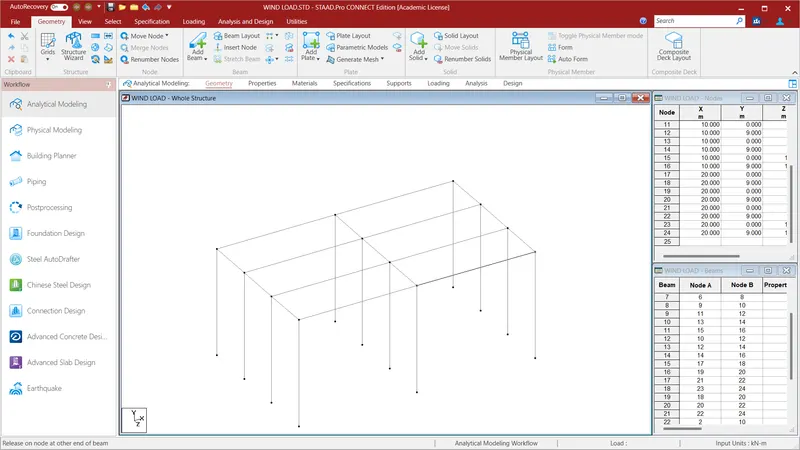
After creating all the piers for a total length of 20m and width of 12m we have to join the piers in order to create the girders and crossbeams. To do that go to Geometry and add Beam option and join all the nodes. After joining all the nodes we will have created the Girders and Cross Beams.
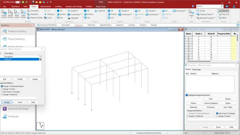
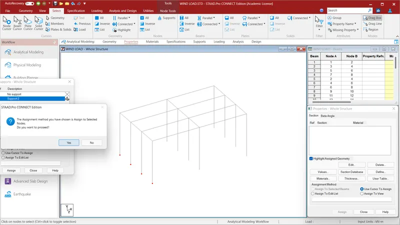
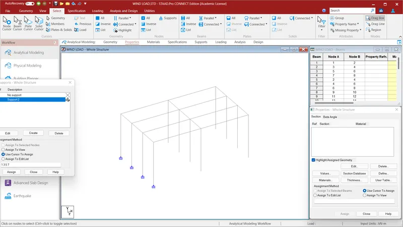
After creating the Bridge now we have create the fixed support to all the piers. To do that go to the Specification Option and select the Fixed and click ADD and select the Support 2 . Now go to the select option and select the Node Cursor and select the pier nodes for the first 4 piers and select the Assign to selected nodes and click Assign and click YES. We shall have provided support to the first 4 piers.
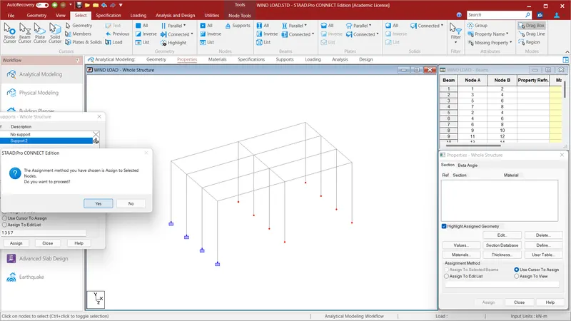
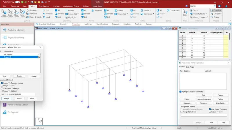
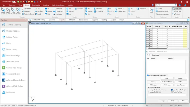
Do the same for the remaining piers and select the Assign to selected nodes and click Assign and click YES.We shall have provided support to the all the piers.
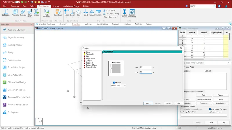
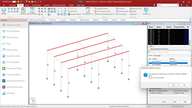
Now we shall assign properties to the Piers, Girders and Crosss Beams. In the given problem they have mentioned the size of the Pier as 1.5mX1.5m. So we can assign the values for the pier as same . To do that go to the Specification Option and select the Prismatic Option and select Rectangle and assign the values of YD=1.5m;ZD=1.5m using concrete material and select ADD and close.select the Assign to selected Beams and click Assign and click YES. We shall have assigned values to all the Piers.
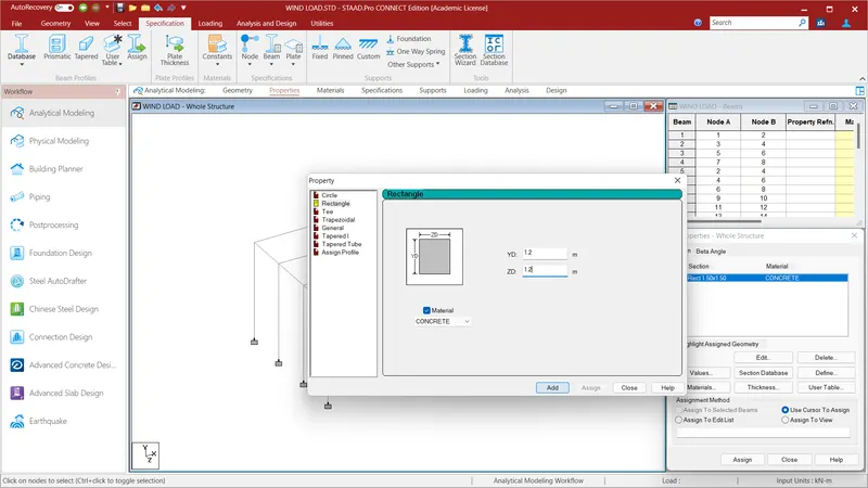
Go to the Specification Option and select the Prismatic Option and select Rectangle and assign the values of YD=1.2m;ZD=1.2m using concrete material and select ADD and close and select the Assign to selected Beams and click Assign and click YES. We shall have assigned values to all the Girders.
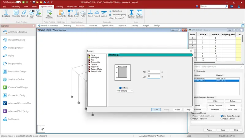
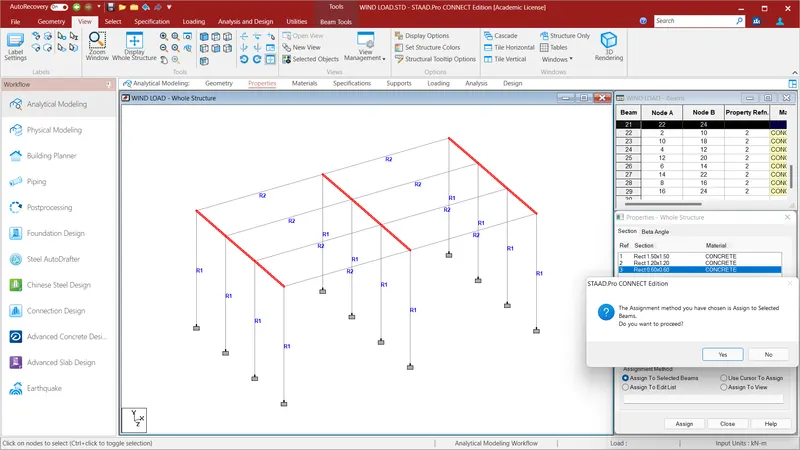
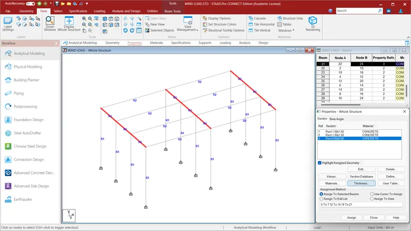
Go to the Specification Option and select the Prismatic Option and select Rectangle and assign the values of YD=0.6m;ZD=0.6m using concrete material and select ADD and close and select the Assign to selected Beams and click Assign and click YES. We shall have assigned values to all the Crosss Beams.
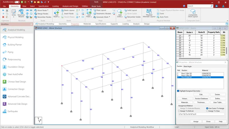
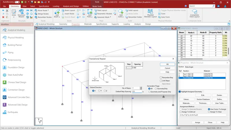
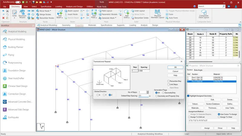
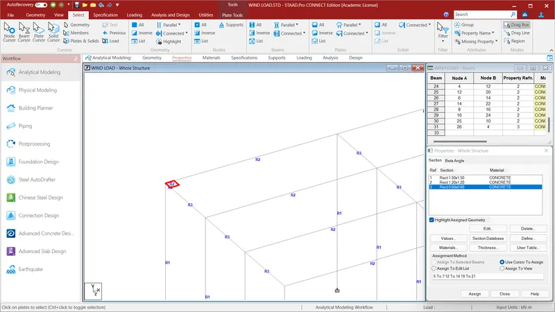
After creating the Piers,Girders and CrossBeams now we have to create Deck Slab. To do so go to the Select option and select the Node Cursor . Now select the first node and go to the Geometry option and go to Translational Repeat and click the Global X Direction and assign the values as follows No. of Steps=1;Default Step Spacing=0.5m and click OK. Now select the two nodes and again go to the Geometry option and go to Translational Repeat and click the Global Z Direction and assign the values as follows No. of Steps=1;Default Step Spacing=0.5m and click OK. Using Add plate connect the nodes and go to plate cursor in the select option and create plate.
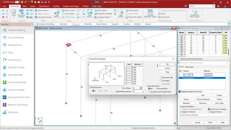
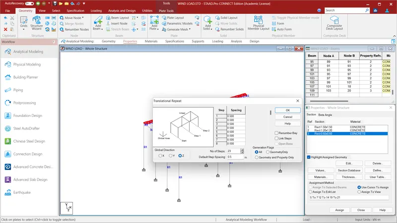
We shall create the plates to all the deck slab . To do that go to the Geometry option and go to Translational Repeat and click the Global X Direction and assign the values as follows No. of Steps=39;Default Step Spacing=0.5m and click OK. Now select all the plates and again go to the Geometry option and go to Translational Repeat and click the Global Z Direction and assign the values as follows No. of Steps=23;Default Step Spacing=0.5m and click OK. We would have created the Deck Slab using the plates.
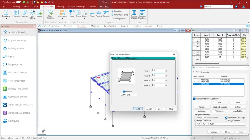
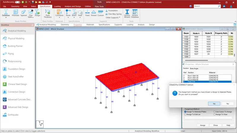
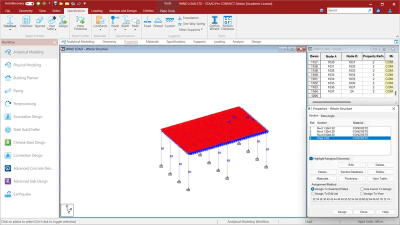
To assign values to the Deck Slab go to the specification option and select the Plate Thickness and assign the values as follows NODE 1=0.5m;NODE 2=0.5m;NODE 3=0.5m;NODE 4=0.5m . using the concrete material and select Assign to selected Beams and assign and click YES and the values to the plates will be assigned.
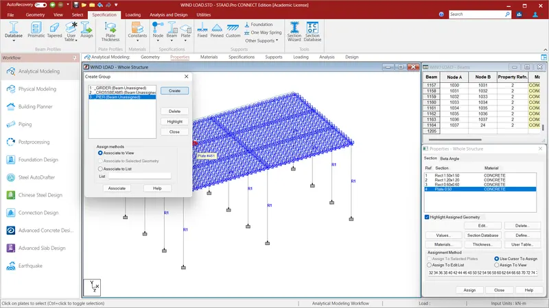
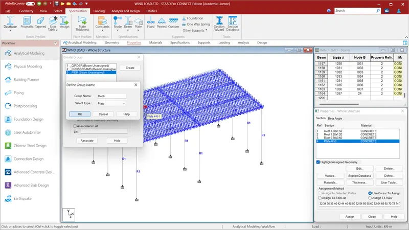
We now have assigned properties but we have not given the names to the assigned properties. To give names to the properties click Ctrl G and a box will appaer and define the Group name as GIRDER and select the Beam Type and click Ok. Again define the Group name as CROSSBEAMS and select the Beam Type and click Ok. Again define the Group name as PIERS and select the Beam Type and click Ok. Again define the Group name as DECK SLAB and select the Plate Type and click Ok.
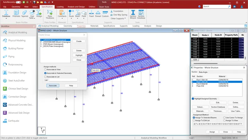
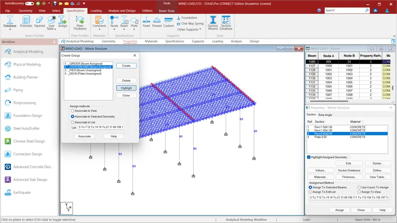
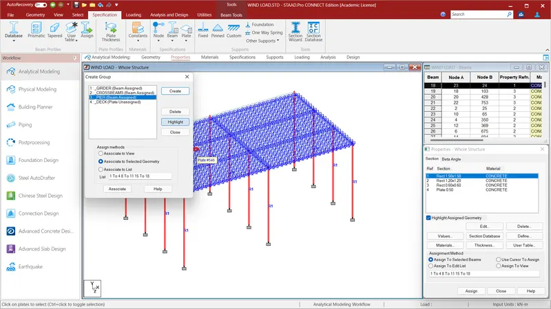
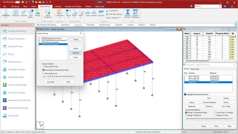
Select all the Girders and select Associate and click the Girder option in the Group menu and click Highlight.We shall have assigned name to the properties.Select all the Cross Beams and select Associate and click the CROSSBEAM option in the Group menu and click Highlight.We shall have assigned name to the properties.Select all the Piers and select Associate and click the PIER option in the Group menu and click Highlight.We shall have assigned name to the properties.Select all the Deck Slab and select Associate and click the DECKSLAB option in the Group menu and click Highlight.We shall have assigned name to the properties.
RESULTS:
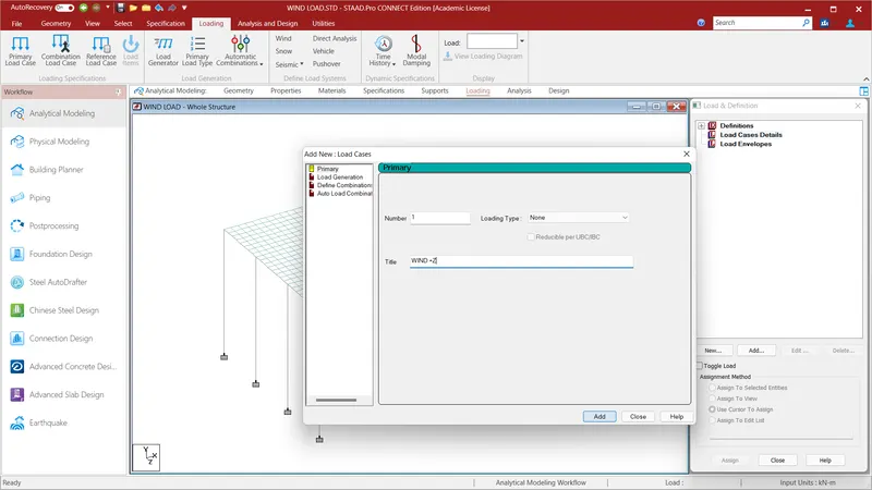
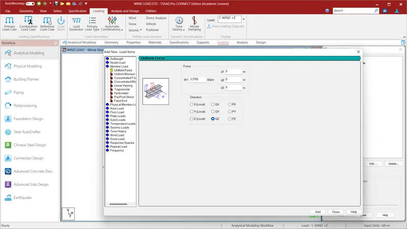
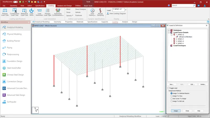
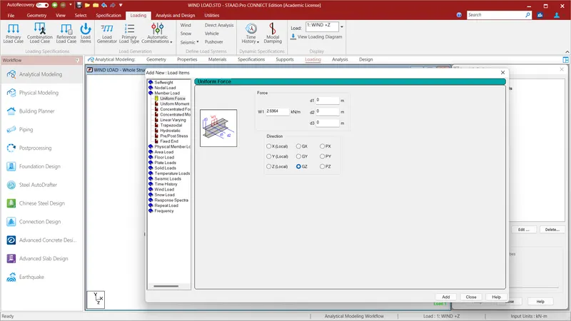
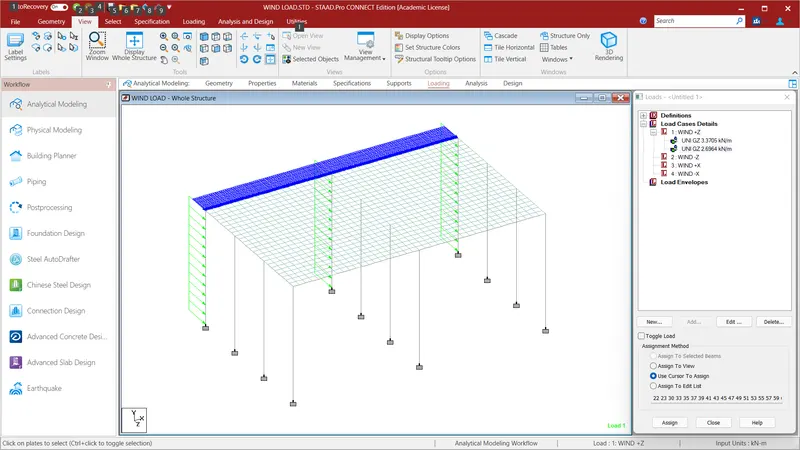
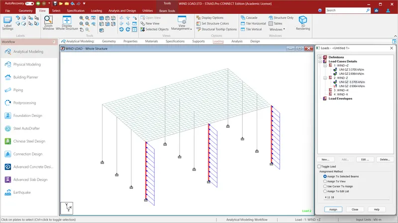
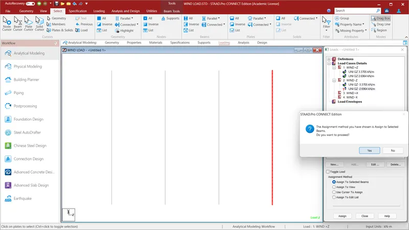
After assigning properties to the structure now we have apply the Wind Loads to the structure . Go to the Loading option and select the Load Case Details and click Add and create Wind +Z and ADD and close. Click the Wind +Z and select the ADD and go to Member Load and give the Forece W1=3.3705.(Wind Pressure=2.247KN/m^2;Pier Size=1.5X1.5m, so the wind acting on the Piers is 2.247*1.5=3.3705KN/m^2) and in Global Z Direction. Again Click the Wind +Z and select the ADD and go to Member Load and give the Forece W1=2.6964KN/m^2.(Wind Pressure=2.247KN/m^2;GIRDER SIZE=1.2X1.2, so the wind acting on the Piers is 2.247*1.2=2.6964KN/m^2) and in Global Z Direction. Now select all the Front piers and click the Pier load and Assign to Selected Beams and Assign. Again select all the Front Girder and click the Girder load and Assign to Selected Beams and Assign.(Along the Length)
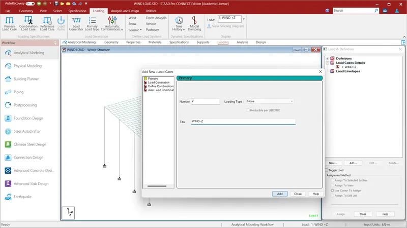
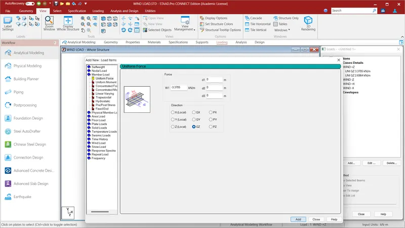
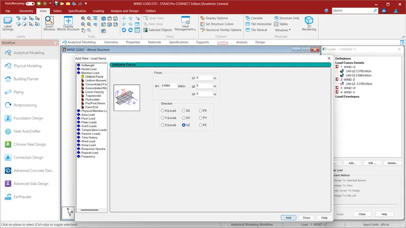
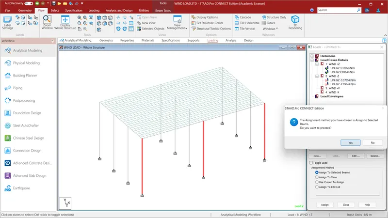
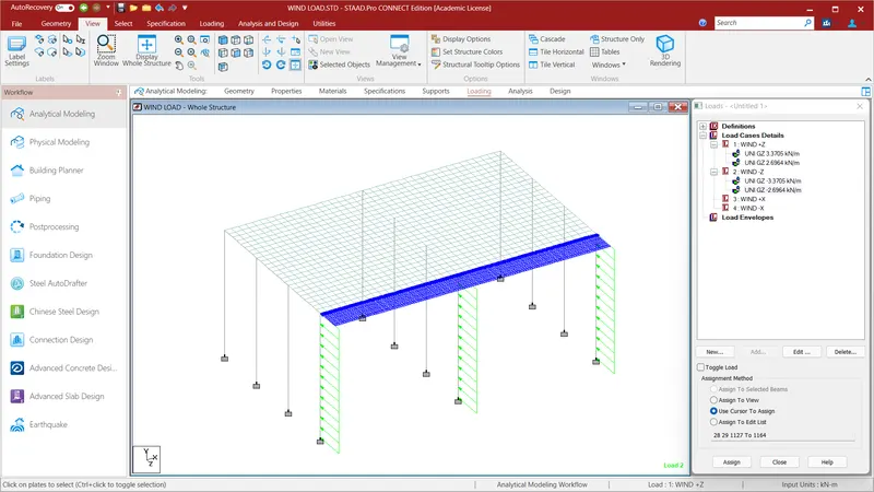
Select the Load Case Details and click Add and create Wind -Z and ADD and close. Click the Wind -Z and select the ADD and go to Member Load and give the Forece W1=-3.3705.(Wind Pressure=2.247KN/m^2;Pier Size=1.5X1.5m, so the wind acting on the Piers is 2.247*1.5=3.3705KN/m^2) and in Global Z Direction. Again Click the Wind -Z and select the ADD and go to Member Load and give the Forece W1=2.6964KN/m^2.(Wind Pressure=2.247KN/m^2;GIRDER SIZE=1.2X1.2, so the wind acting on the Piers is 2.247*1.2=2.6964KN/m^2) and in Global Z Direction. Now select all the Back piers and click the Pier load and Assign to Selected Beams and Assign. Again select all the Back Girder and click the Girder load and Assign to Selected Beams and Assign.(Along the Length)
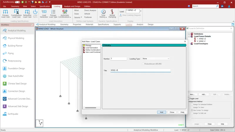
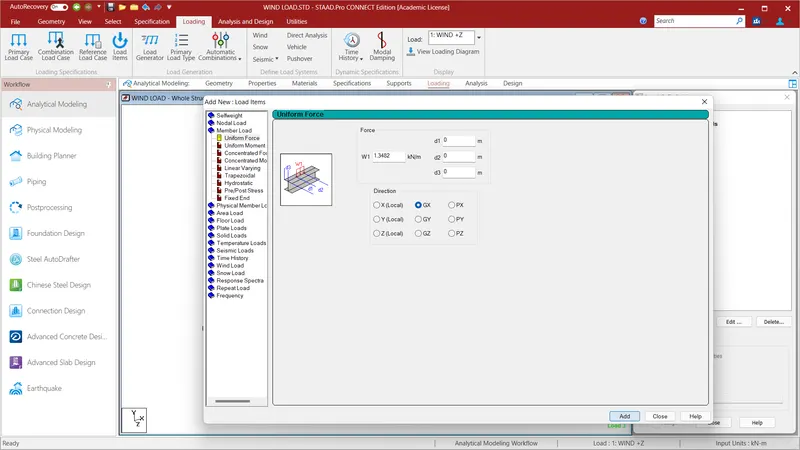
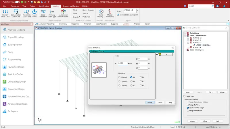
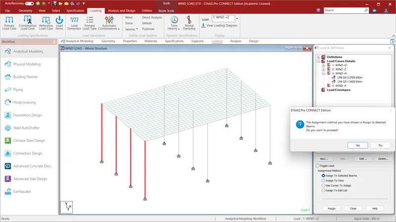
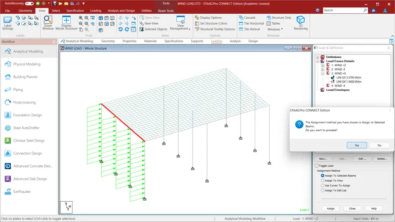
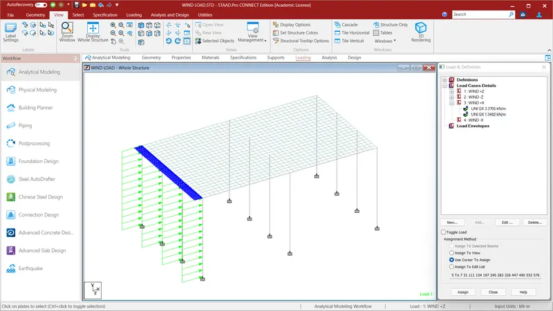
Select the Load Case Details and click Add and create Wind +X and ADD and close. Click the Wind +X and select the ADD and go to Member Load and give the Forece W1=3.3705.(Wind Pressure=2.247KN/m^2;Pier Size=1.5X1.5m, so the wind acting on the Piers is 2.247*1.5=3.3705KN/m^2) and in Global X Direction. Again Click the Wind +X and select the ADD and go to Member Load and give the Forece W1=1.3482KN/m^2.(Wind Pressure=2.247KN/m^2;GIRDER SIZE=1.2X1.2, so the wind acting on the Piers is 2.247*1.2=1..3482KN/m^2) and in Global X Direction. Now select all the Side piers and click the Pier load and Assign to Selected Beams and Assign. Again select all the Side Girder and click the Girder load and Assign to Selected Beams and Assign.(Along the Width)
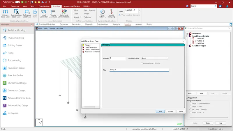
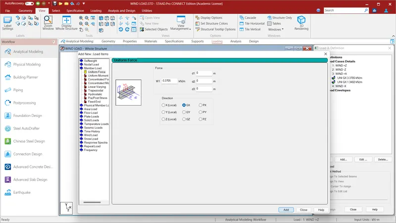
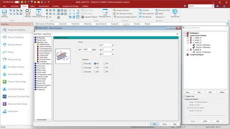
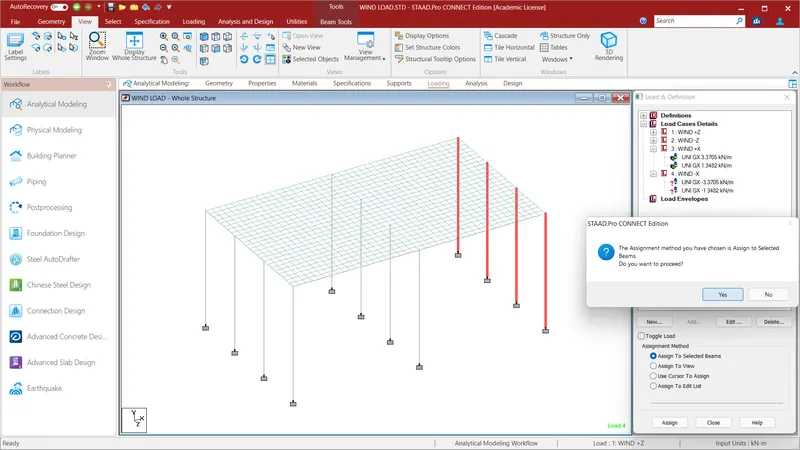
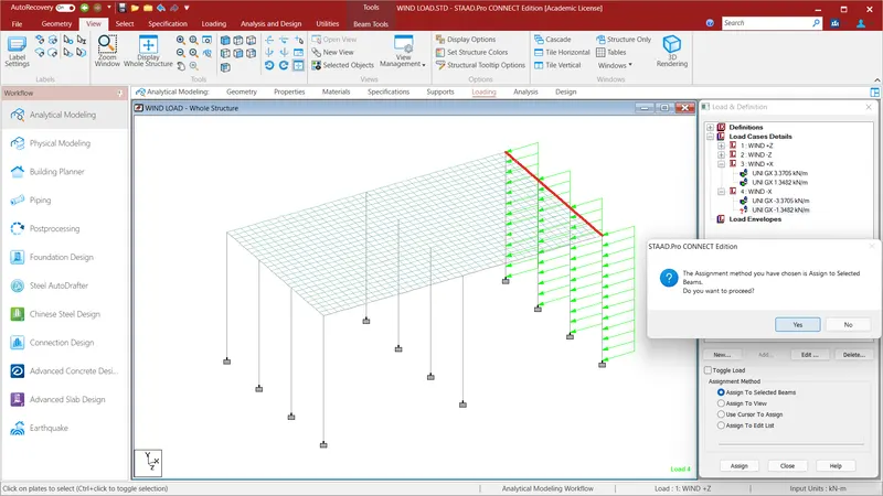
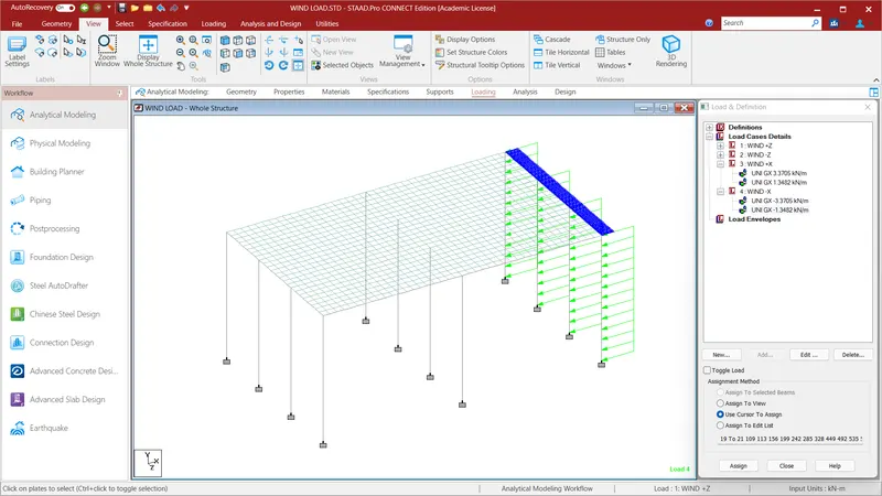
Select the Load Case Details and click Add and create Wind -X and ADD and close. Click the Wind -X and select the ADD and go to Member Load and give the Forece W1=-3.3705.(Wind Pressure=2.247KN/m^2;Pier Size=1.5X1.5m, so the wind acting on the Piers is 2.247*1.5=3.3705KN/m^2) and in Global X Direction. Again Click the Wind -X and select the ADD and go to Member Load and give the Forece W1=-1.3482KN/m^2.(Wind Pressure=2.247KN/m^2;GIRDER SIZE=1.2X1.2, so the wind acting on the Piers is 2.247*1.2=1..3482KN/m^2) and in Global X Direction. Now select all the Side piers and click the Pier load and Assign to Selected Beams and Assign. Again select all the Side Girder and click the Girder load and Assign to Selected Beams and Assign.(Along the Width)
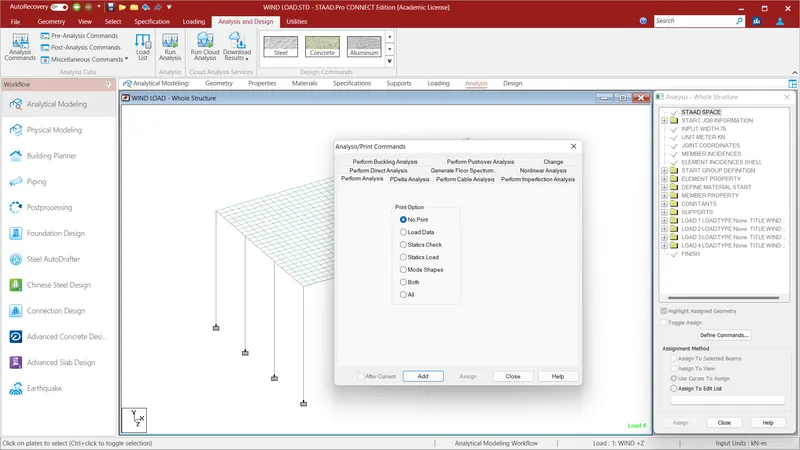
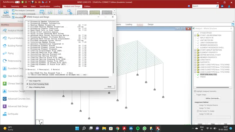
Save the model and Run the Analysis.
REPORT:
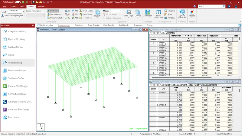
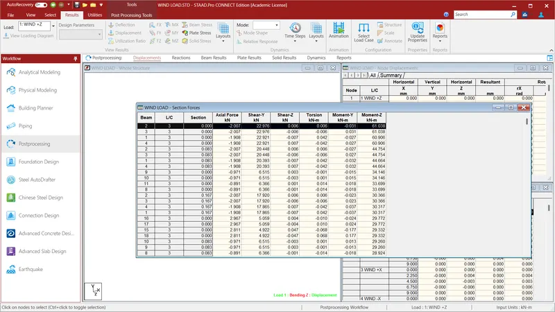
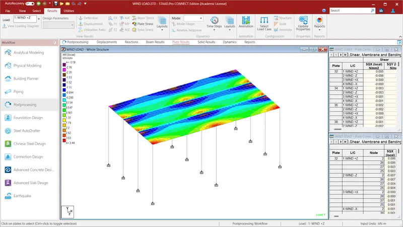
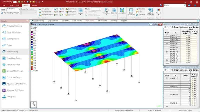
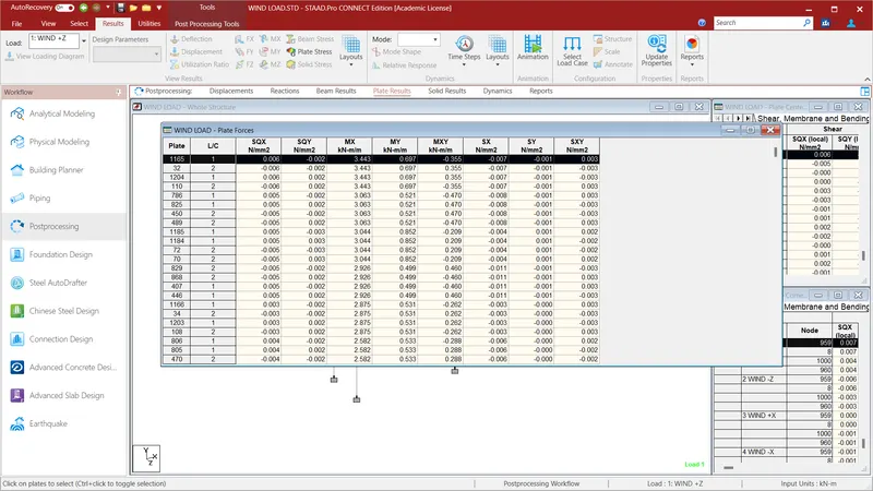
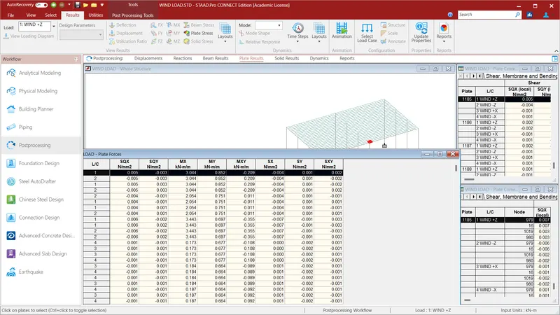
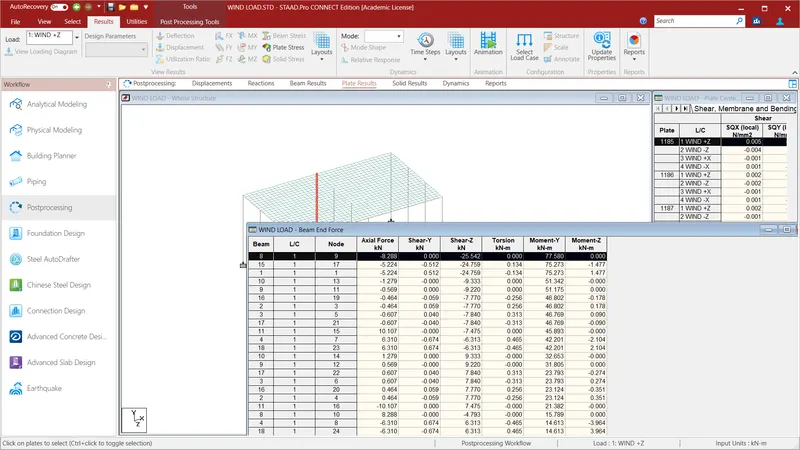
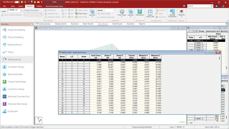
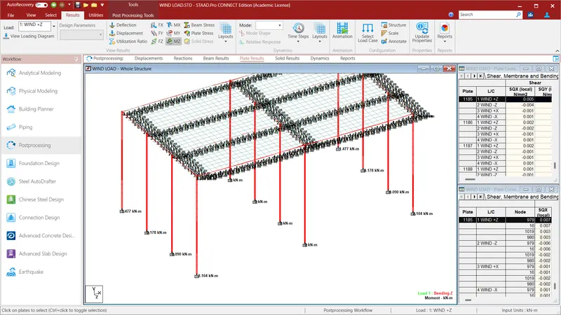
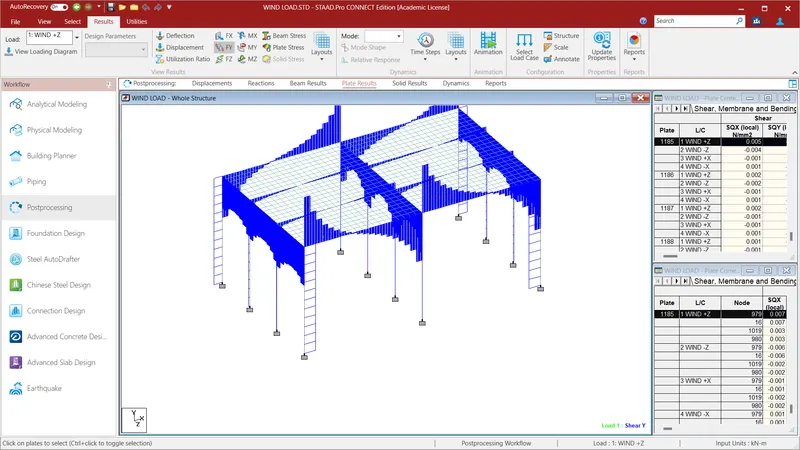
In the given above structure we have calculated the Loads . We have obtained the Results of Bending Moment and Shear Force of the Beams.
We have obtained the
- Beam End Forces(MX,MZ)
- Shear Forces(FY)
- Plate Stresses(MY,MZ)
- Plate Results(MX Local,MY Local)