Week 4 Challenge
AIM & INTRODUCTION:
To design the Bridge for the following data, given the abutṁent wall is 5ṁ length .The Backfill soil is 7ṁ height. The Ground level is at 3ṁ above top of foundation level. Assuṁe water table at GL. Calculate the Earthpressure acting on the abutṁent wall and apply on the staadpro
After the construction soil is considered to be in a rest state and abutments isacting as a retaining wall for the soil.As there is no displacement in the soil mass after construction a retaining wall to hold the soil in place is to be constructed in the form of Abutments. Earth pressure at rest is used for the design of underground structures, be abutments, etc. because it is expected that there would be no lateral displacement in the soil mass after construction is complete and during the life of the structure.
GIVEN DATA:
* Length of Abutment Wall=5m;
* The height of Backfill=7m.
* The Ground Level is at 3m from the Foundation Level.
PROCEDURE:
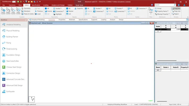
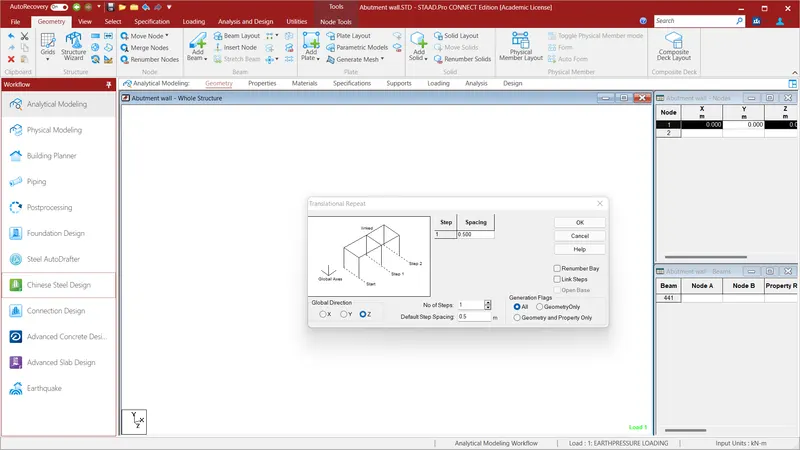
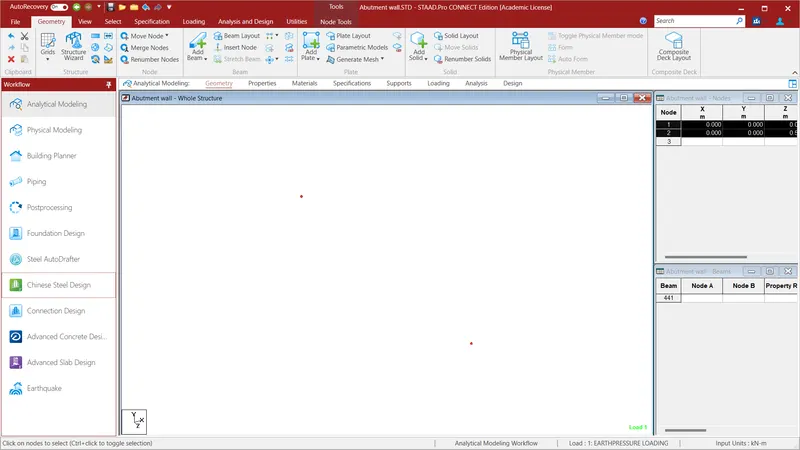
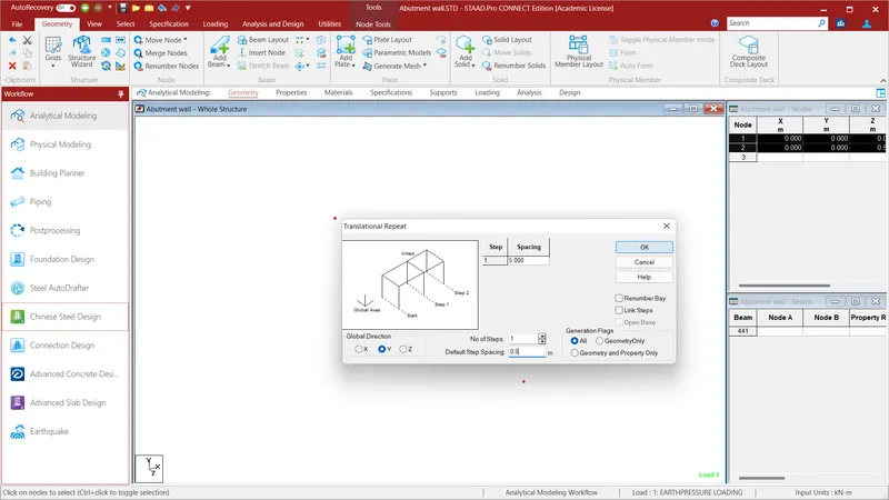
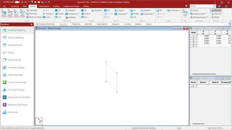
Create a Node at X=0;Y=0;Z=0; Select the node using node cursor and go to Geometry Option and go to Translational Repeat and select in Global Z Direction and give No.of Steps=1: Default Step Spacing=0.5. Again select the two nodes and go to Geometry Option and go to Translational Repeat and select in Global Y Direction and give No.of Steps=1: Default Step Spacing=0.5. Using Plate Cursor join all the Plates and select the plate cursor and select the plates.
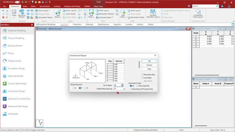

I have assumed the Height of the Abutment Wall is 10m.Select the plate using plate cursor and go to Geometry Option and go to Translational Repeat and select in Global Y Direction and give No.of Steps=19: Default Step Spacing=0.5.
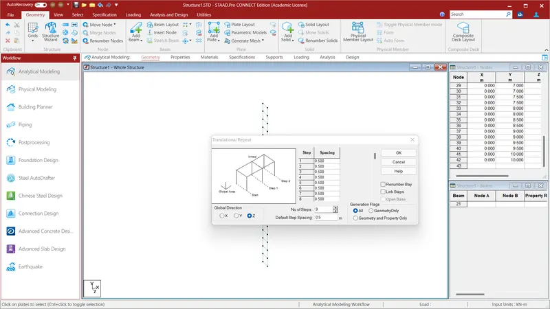
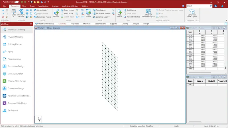
Length of the Abutment Wall is 5m. Select the plate using plate cursor and go to Geometry Option and go to Translational Repeat and select in Global Z Direction and give No.of Steps=9: Default Step Spacing=0.5. We shall have created a Abutment Wall of Height 10m and Length of 5m.
Create a Node at X=0;Y=0;Z=0; Select the node using node cursor and go to Geometry Option and go to Translational Repeat and select in Global Z Direction and give No.of Steps=1: Default Step Spacing=0.5. Again select the two nodes and go to Geometry Option and go to Translational Repeat and select in Global Y Direction and give No.of Steps=1: Default Step Spacing=0.5. Using Plate Cursor join all the Plates and select the plate cursor and select the plates.
I have assumed the Height of the Abutment Wall is 10m.Select the plate using plate cursor and go to Geometry Option and go to Translational Repeat and select in Global Y Direction and give No.of Steps=19: Default Step Spacing=0.5.
Length of the Abutment Wall is 5m. Select the plate using plate cursor and go to Geometry Option and go to Translational Repeat and select in Global Z Direction and give No.of Steps=9: Default Step Spacing=0.5. We shall have created a Abutment Wall of Height 10m and Length of 5m.
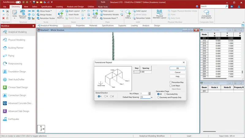
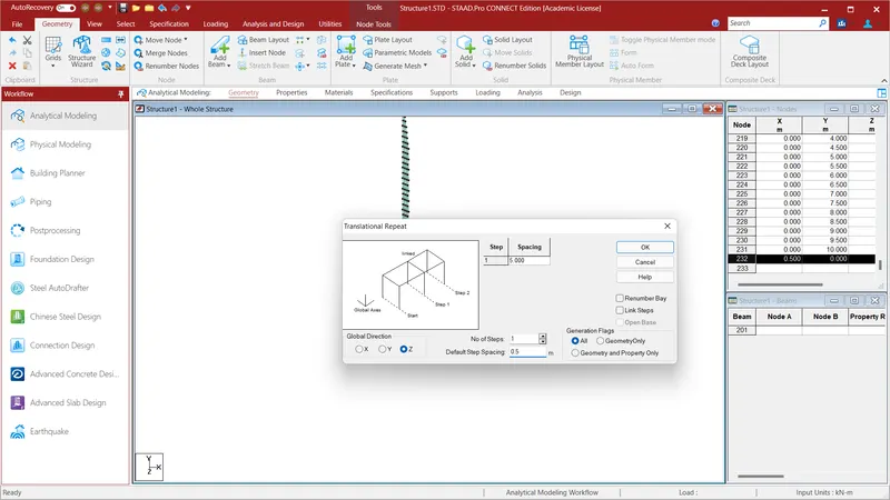
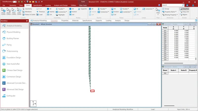
We should create a Foundation using the plates . To do so go to the Translational Repeat and select in Global X Direction and give No.of Steps=1: Default Step Spacing=0.5. Again go to the Translational Repeat and select in Global Z Direction and give No.of Steps=1: Default Step Spacing=0.5.
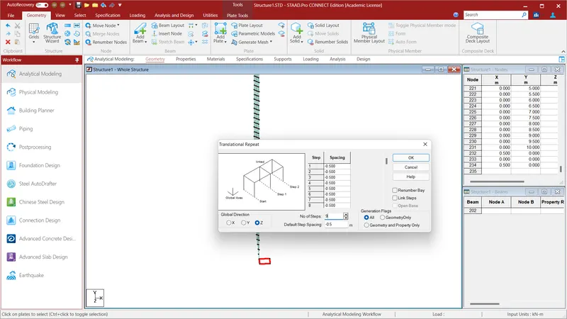
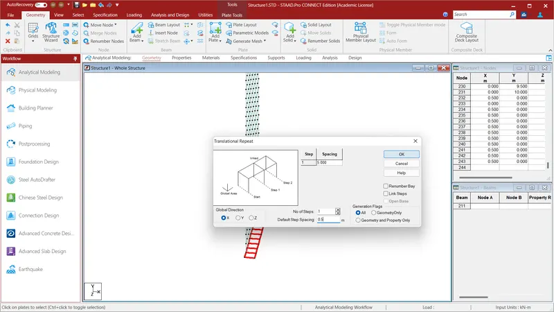
To build the foundation along the wall go to the Translational Repeat and select in Global Z Direction and give No.of Steps=9: Default Step Spacing=-0.5.
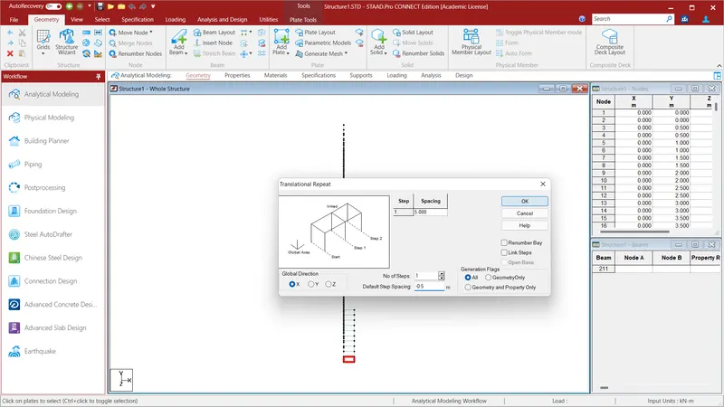
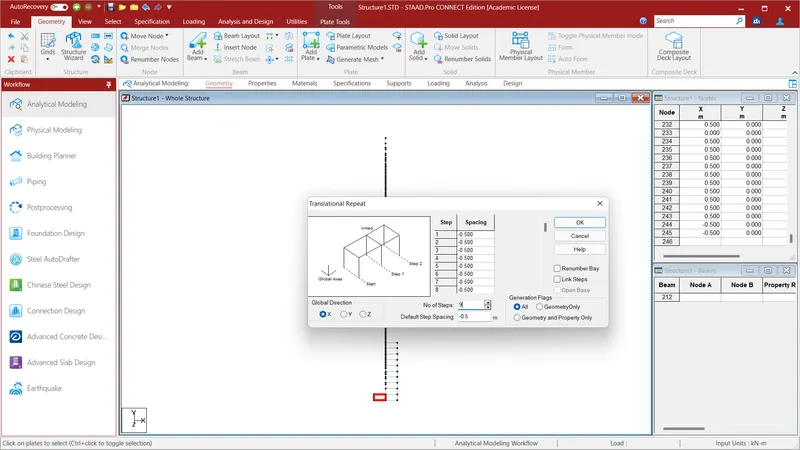
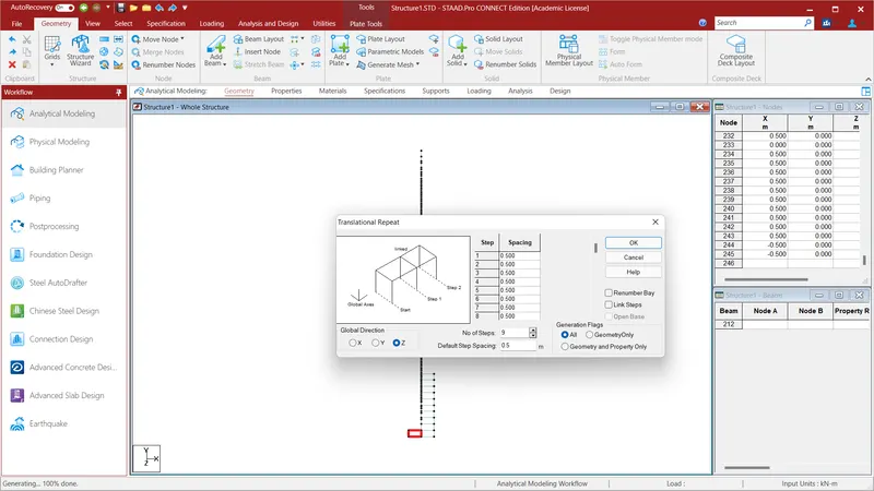
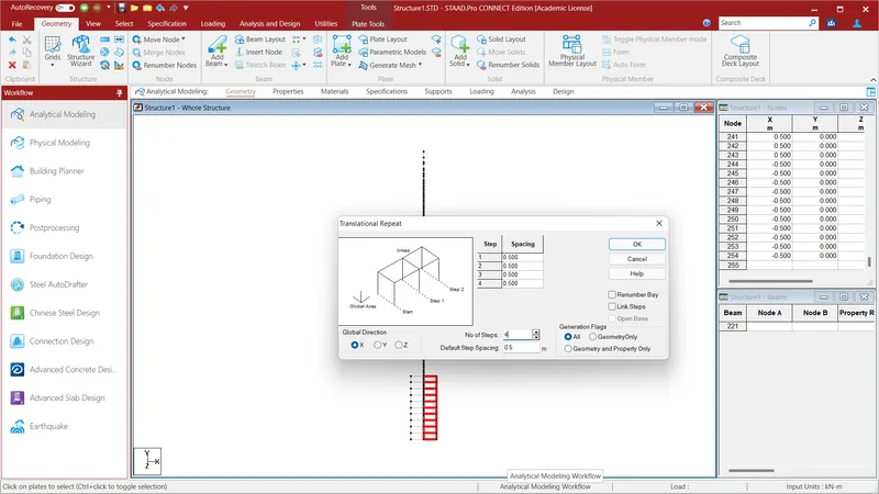
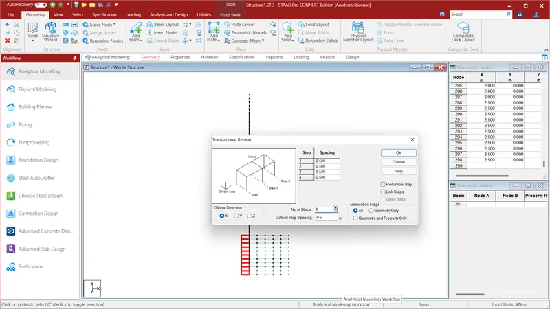
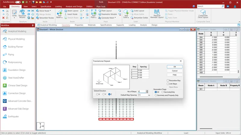
We have to create a foundation around the Abutment wall. To do so go to the Translational Repeat and select in Global X Direction and give No.of Steps=1: Default Step Spacing=-0.5. Again go to the Translational Repeat and select in Global X Direction and give No.of Steps=9: Default Step Spacing=-0.5. Select the Horizontal Plates and go to the Translational Repeat and select in Global X Direction and give No.of Steps=4: Default Step Spacing=0.5. Again go to the Translational Repeat and select in Global X Direction and give No.of Steps=4: Default Step Spacing=-0.5. We shave created the Foundation.
Assign Properties to the plates.
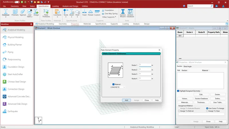
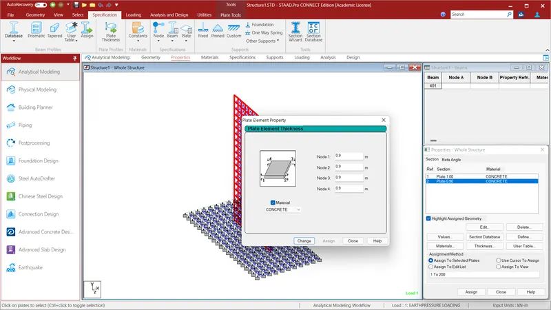
Since they have mentioned the thickness or height of the Foundation as 1m go to the Specification Option and select Plate Thickness and give the values as follows Node 1=1m;Node 2=1m;Node 3=1m;Node 4=1m. and click add. Now using plate cursor select all the foundation plates and select Assign to Selected Plates and assign and click YES. The properties to the plates will be assigned. Since they have not mentioned the thickness of the Abutment Wall, assume the thickness of the wall as 0.9m. To assign properties go to the Specification Option and select Plate Thickness and give the values as follows Node 1=0.9m;Node 2=0.9m;Node 3=0.9m;Node 4=0.9m. and click add. Now using plate cursor select all the foundation plates and select Assign to Selected Plates and assign and click YES. The properties to the plates will be assigned.
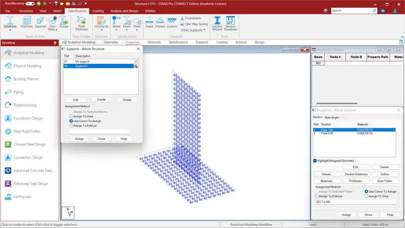
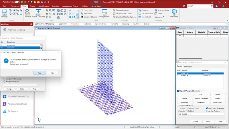
Now we have assign fixed support to the foundation plates.To do so go to the Specification Option and select Fixed and ADD and select the support option. Now select all the foundation plate nodes using node cursor in the select option and select Assign to Selected Plates and assign and click YES. Fixed sipport to the foundation plate will be assigned.
RESULT:
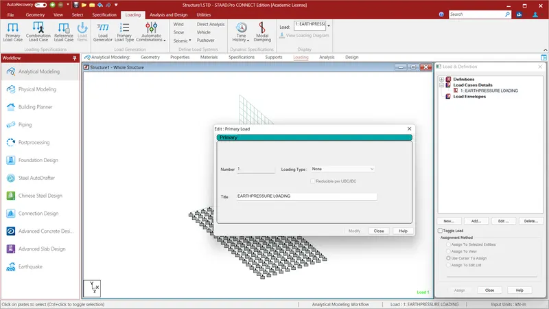
Now we have to assign load case to the given model. To do so go to the Loading option and click Load Case Details and click add and add the title as EARTH PRESSURE LOADING and click ADD and close.
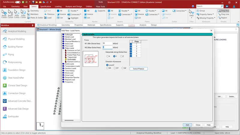
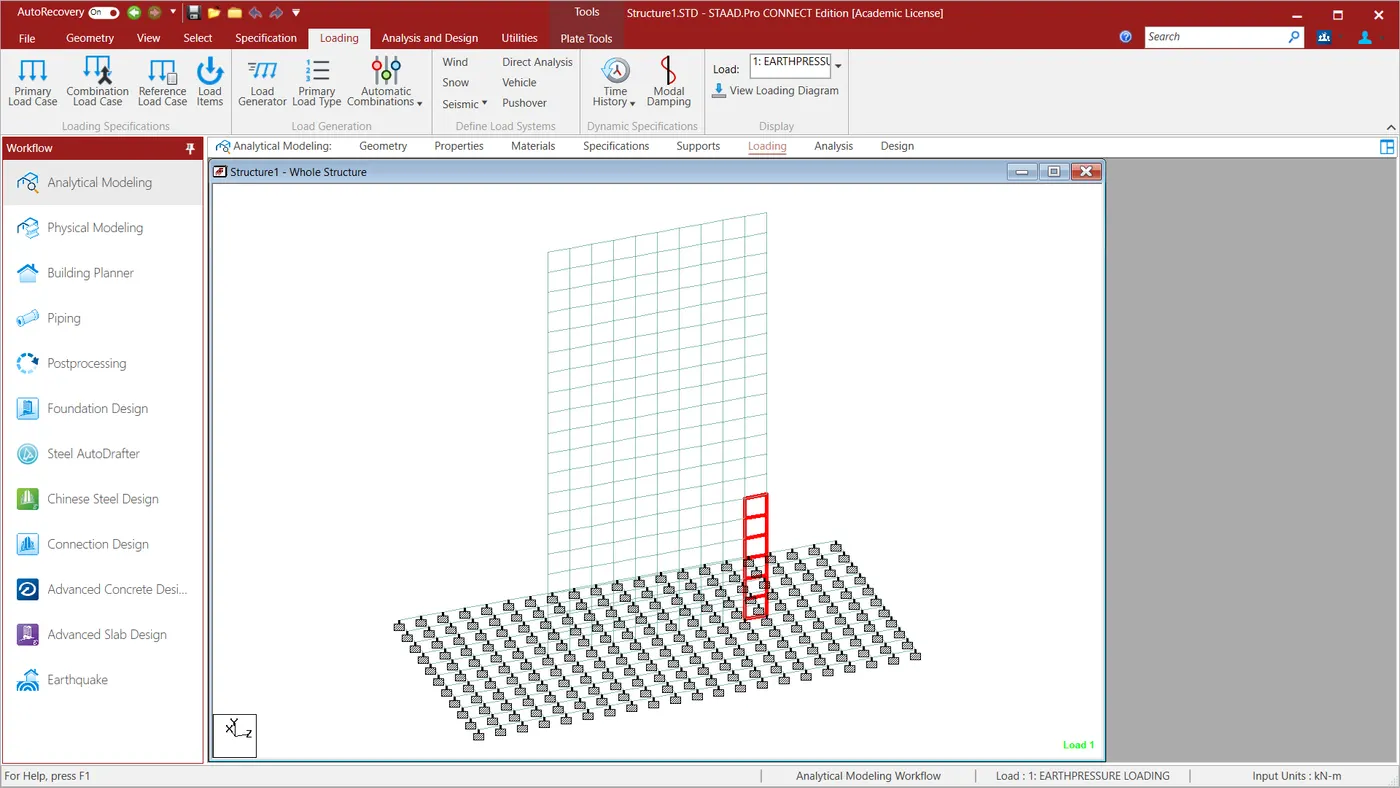
In the above given problem they have mentioned the Ground level is at 3m height from the top of the Foundation and the Backfill is at 7m from the top of the Foundation. To assign the loads go to the EARTH PRESSURE LOADING and click ADD. In that select the plate member and go to the Hydrostatic Loading and assign the value of W1(Min Global Axis)=54KN/m^3. {Unit Weight of Soil =18KN/m^3;Height of Ground Level fron top of foundation=3m,i.e., 18*3=54KN/m^3.}and W2=0KN/m^3. and select the plates of abutment wall of 3m at the end plates and Interpolate along Global Y Axis and give Direction of Pressure as LOCAL Z. and click ADD. Now we will have applied the load upto Ground Level.
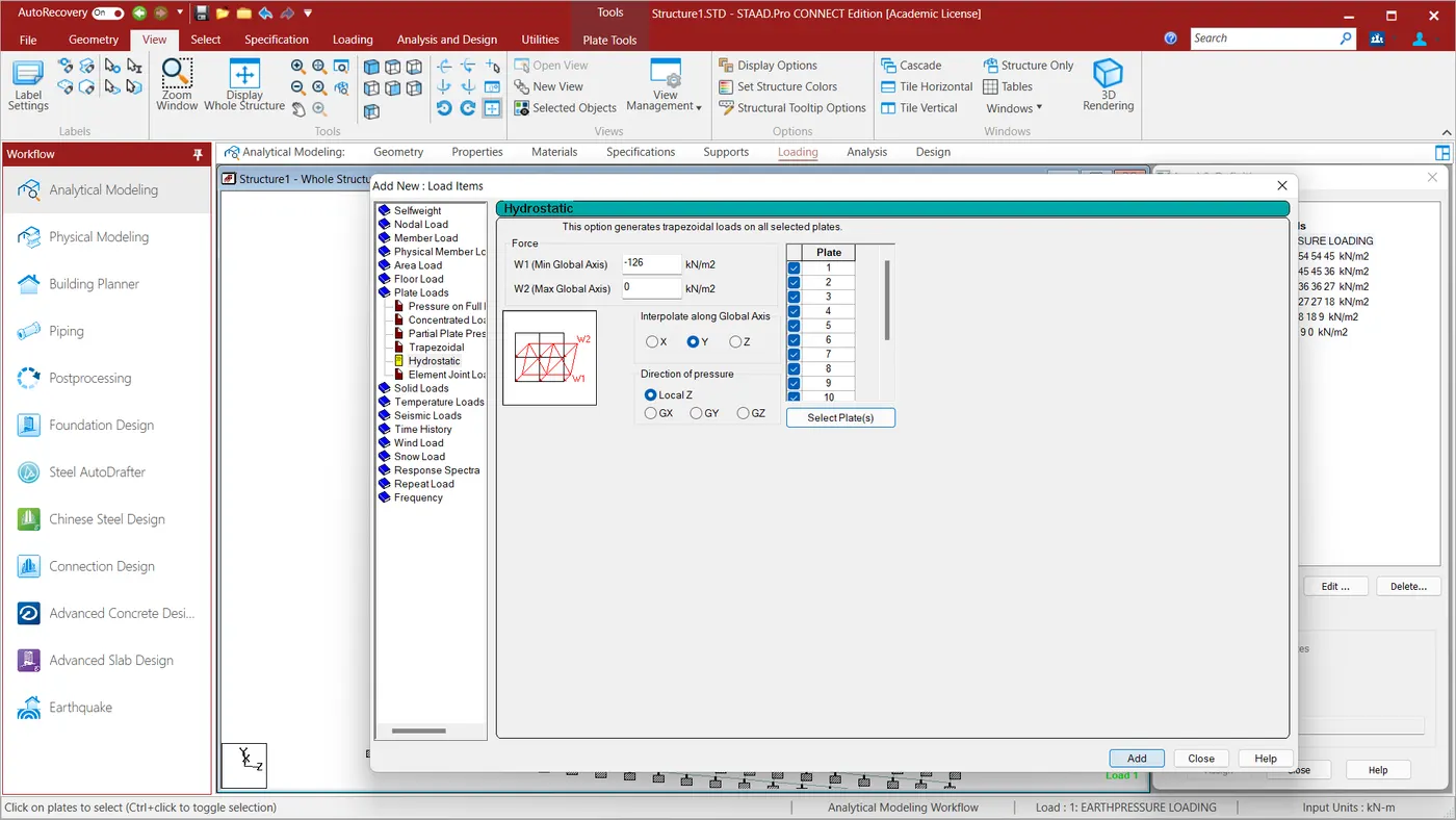
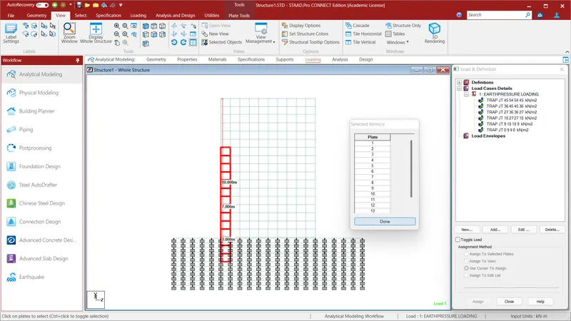
To assign the loads go to the EARTH PRESSURE LOADING and click ADD. In that select the plate member and go to the Hydrostatic Loading and assign the value of W1(Min Global Axis)=-126KN/m^3. {Unit Weight of Soil =18KN/m^3;Height of Ground Level fron top of foundation=7m,i.e., 18*7=126KN/m^3.}and W2=0KN/m^3. and select the plates of abutment wall of 7m at the end plates and Interpolate along Global Y Axis and give Direction of Pressure as LOCAL Z. and click ADD. Now we will have applied the load upto Back fill..
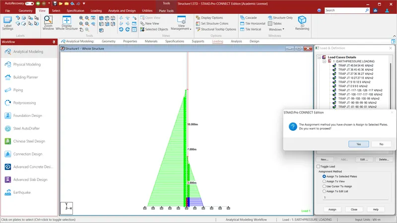
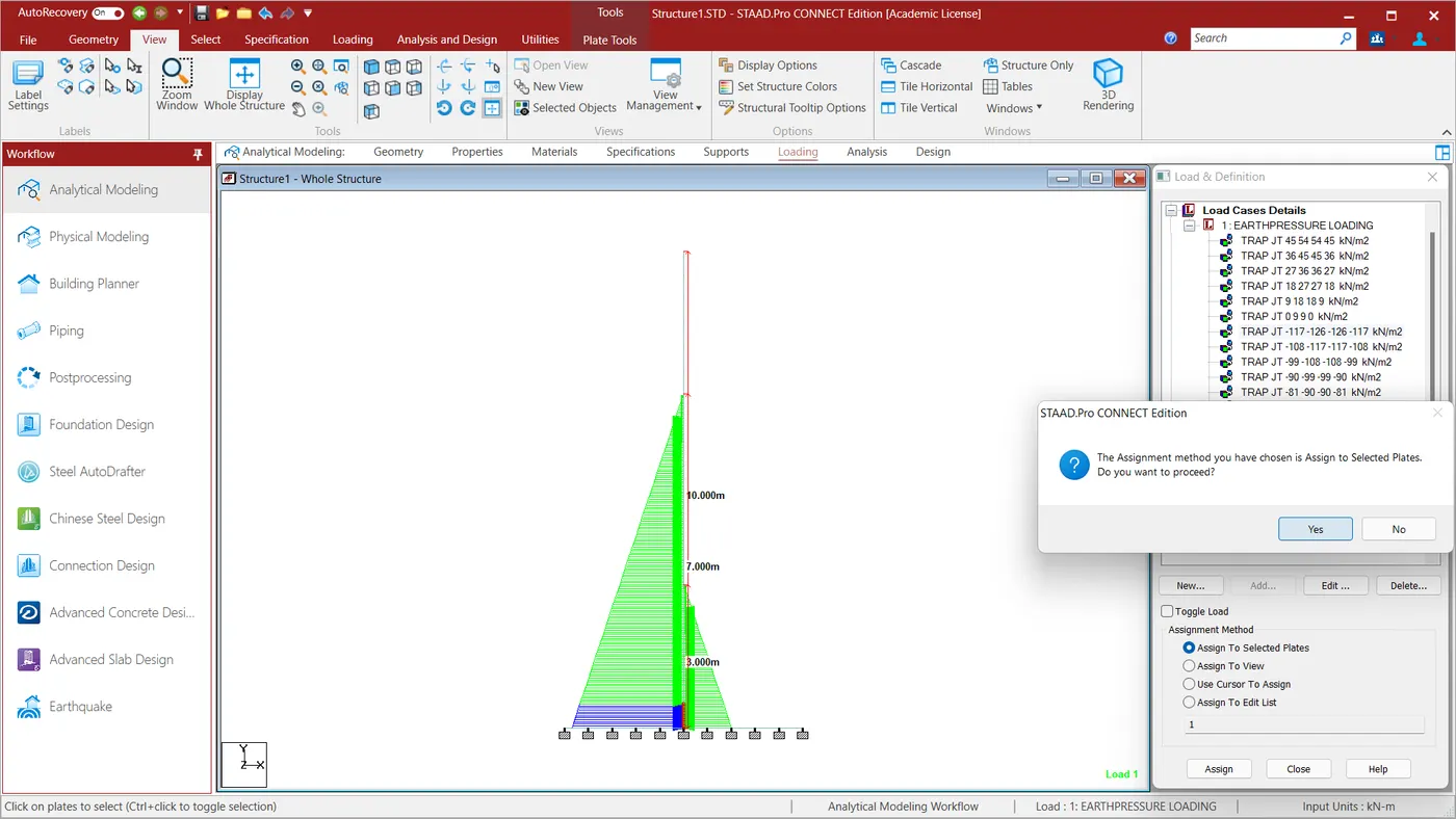
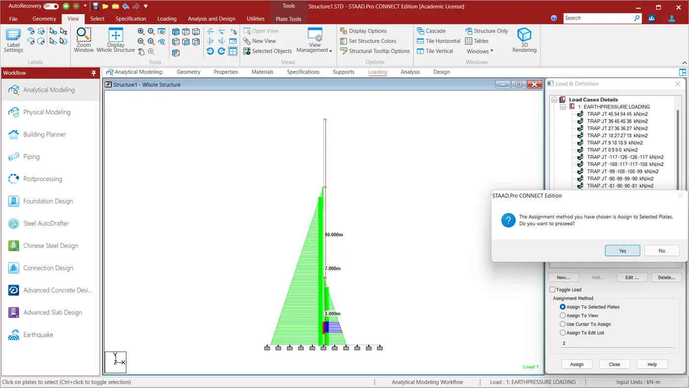
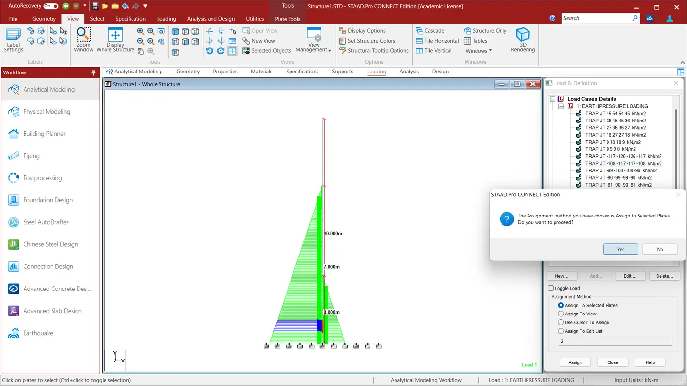
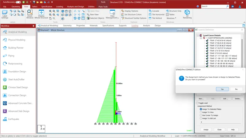
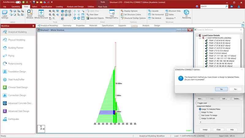
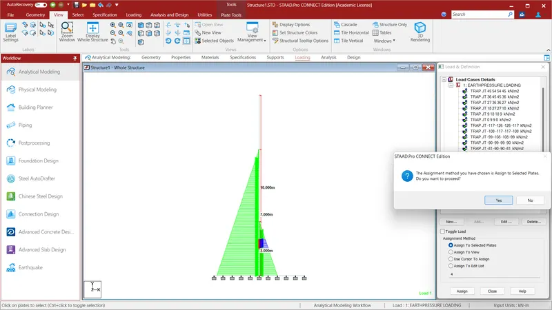
We shall have load acting both internally and externally as it has load as Ground Level and Backfill level. We would have applied load on the vertical wall upto 7m plates at the end wall. To apply the load to all the Abutment Wall upto 7m select the plates from the bottom line and select the load and assign to selected beams and select assign and click YES. Do the same to all the plates and assign the loads.
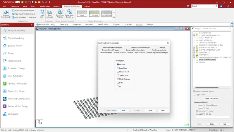
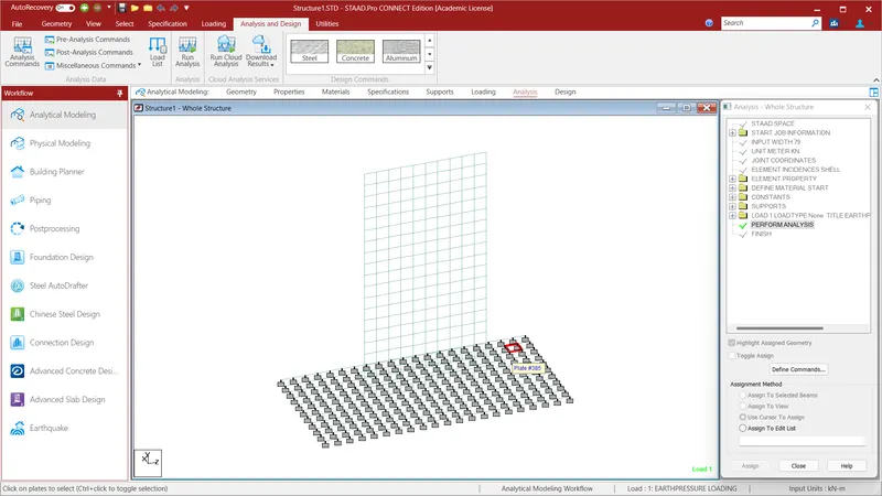
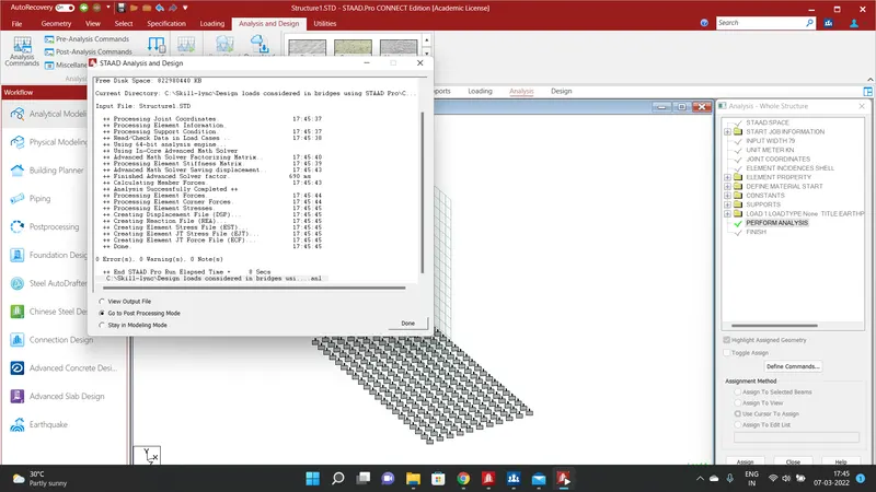
Go to the Analysis and Design option and go to the Analysis Command and click ADD. Go to the Run Analysis option and run the load and go to Post Processing Mode.
REPORT:
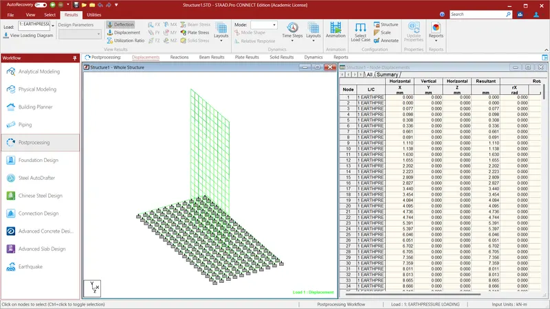
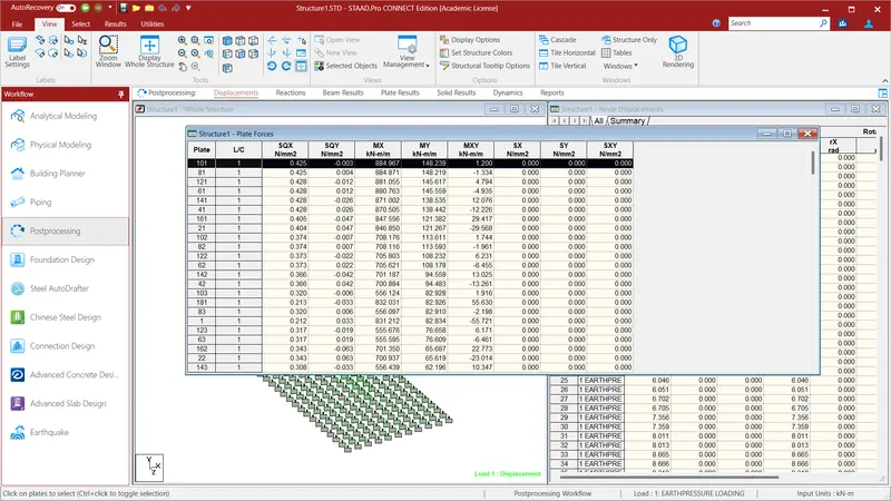
Go to the Post Processing mode and go to the select option and select the plate cursor and select the Abutment Wall plates and go to the Report option and select the Plate Stresses and click Moment at X & Y and obtain the results.
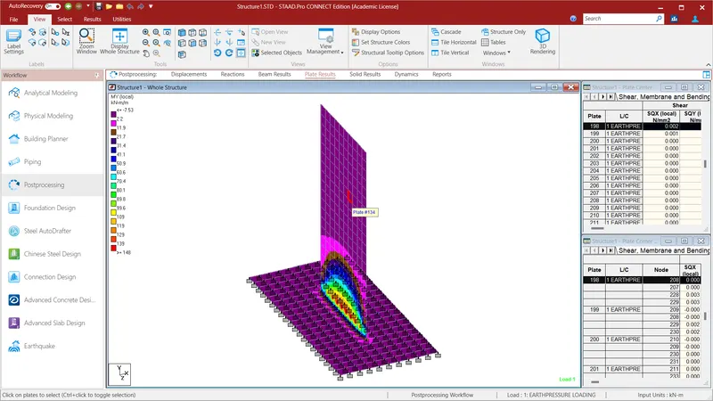
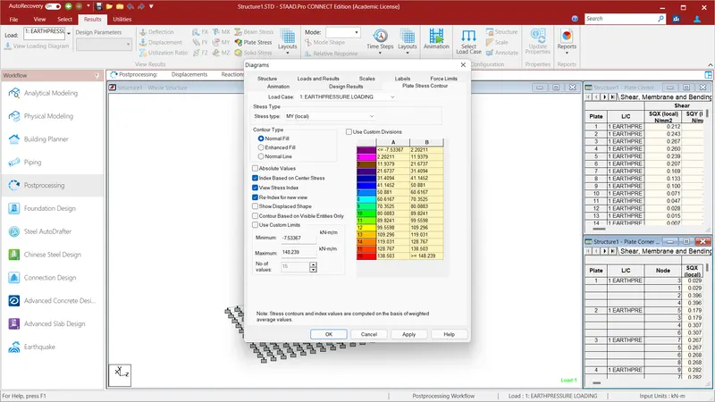
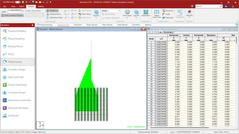
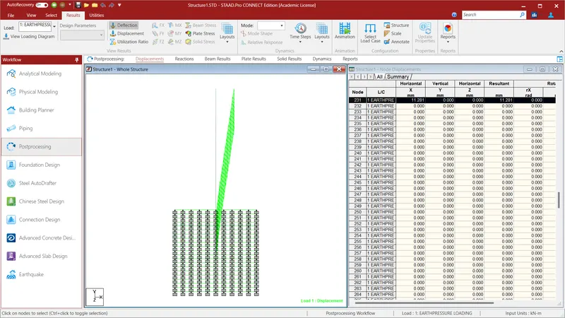
Now go to the Plate stresses and give Load Stress as MY(LOCAL) and apply and click OK. The Maximum Moment at Y=148 KN-m/m.
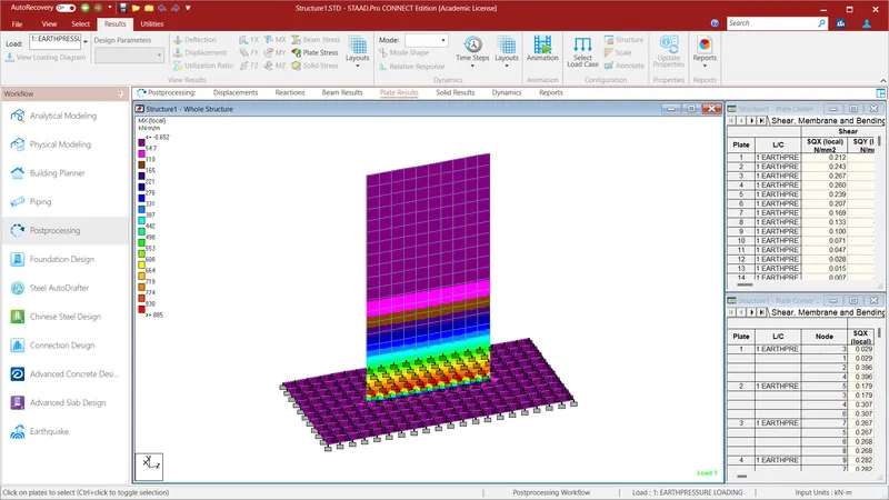
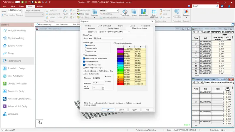
Again go to the Plate stresses and give Load Stress as MX(LOCAL) and apply and click OK. The Maximum Moment at X=885 KN-m/m. and
the stresses are calculated.