Week 9 Challenge
Complete the energy management strategy model with battery, UC and fuel cell for the positive power and distribute the power demand among these components. Set simulation stop time to 598 sec.
The output of the model should be the power request from UC, fuel cell and battery.
Aim:To design the energy management strategy model with battery, UC and fuel cell for the positive power and distribute the power demand among these components.
Energy management system
Flowchart:
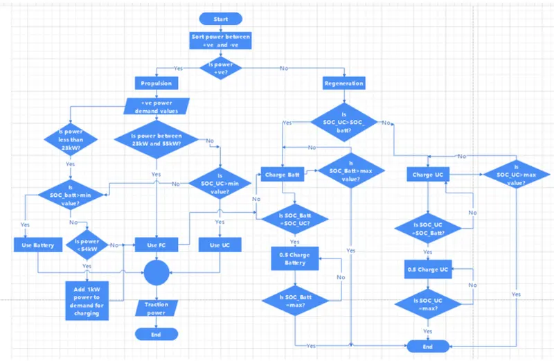
The above flowchart explains the condition for load sharing by energy management systems.It is used to design the simulink model for energy management system.
Blocks used:
Constant,signal builder,switch,Interval test,gain,greater than,and,equal to,add,goto,from,in,out,scope.
Model:
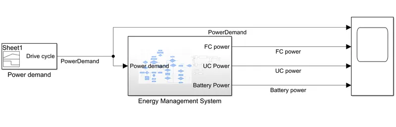
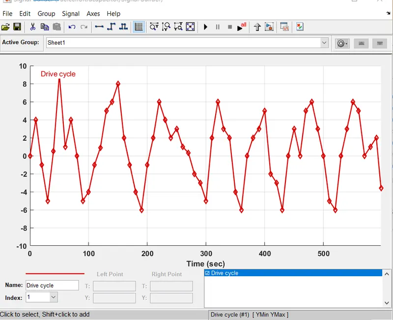
For the input we are providing a drive cycle as the input from the signal builder to the Energy management system.
Signal builder:
Energy management system:
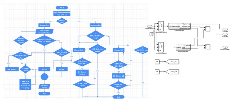
The SOC of ultracapacitor and battery can be given manually to analyse the result and for better understanding of the working algorithm.
If the power demand is positive that is used for propulsion.
The load demand sharing algorithm has to be delivered has load.
Positive power subsystem:
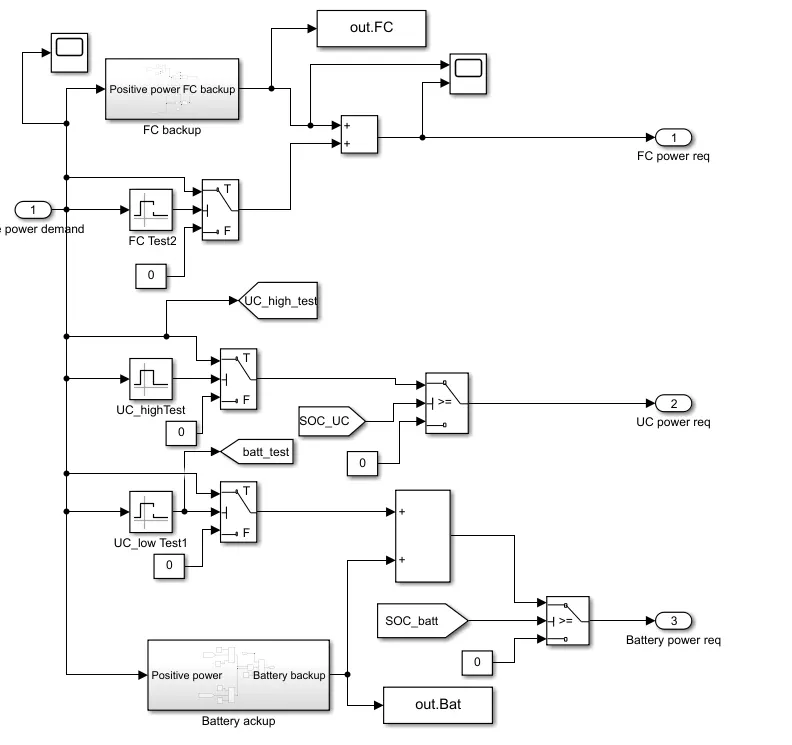
The operating range for fuel cell is 23kw to 55kw
For this we used a interval test.
The operating range for UC high test kept range as 55kw to inf
The operating range for UC low test kept range as 0 to 23kw
The active area fuel cell is 420 cm^2
The operating range starts from current density of 0.24A/cm^2 and ends at 0.76A/cm^2,then the average voltage of each cell is 0.6v.
If 380 cells are in series then the voltage is 380*0.6=228v
Lower limit of current=420*0.24=100.8A
Upper limit of current=420*0.76=319A
Lower power limit=228*100.8=22.9kw
Upper power limit=228*319=72.7kw,at this efficiency is less.
FC backup:
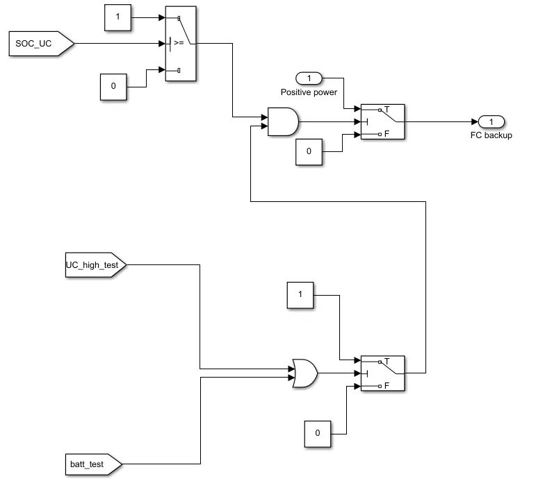
If the SOC of UC is less than minimum value,then this power has to be met by battery.
If both SOC of battery and UC is less than the minimum value then the power has to be delivered by cell.
Battery Backup:
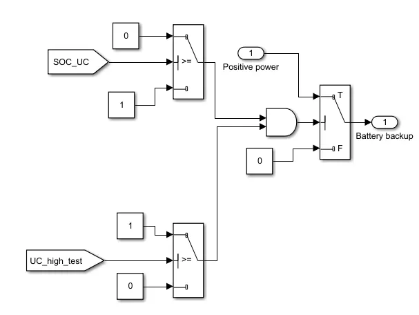
If the SOC is less than minimum value,then this power has to be delivered by fuel cell
Negative power:
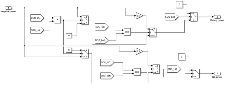
If the SOC of UC and battery is equal to 0.5C charge is done for both UC and battery
If the SOC of battery is greater than UC then the negative power is used to charge the UC as the same way as battery.
Output:
If the SOC_UC=SOC_batt,SOC_UC=0.8,SOC_batt=0.8
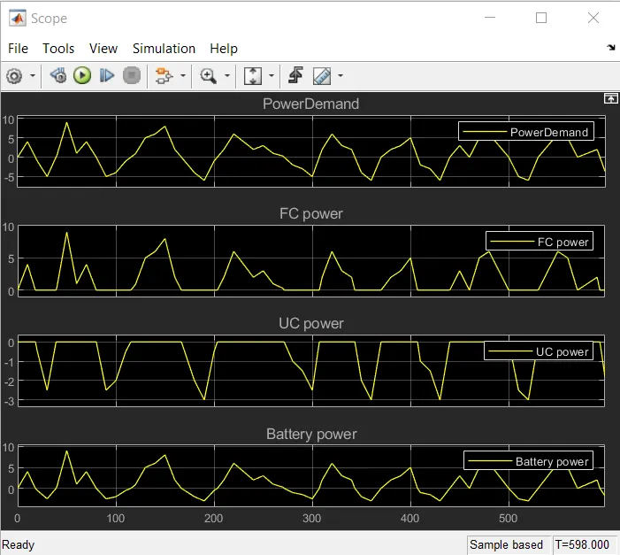
If both SOC_UC ansd SOC_batt are equalthen the negative power is shared equally between ultracapacitor and battery for charging,the positive power is shared among the components according to the energy sharing algorithm.
If SOC_UC <SOC_batt,SOC_UC=0.6,SOC_batt=0.8

Then the negative charge is completely used to ultracapacitor.
If SOC_UC>SOC_batt,SOC_UC=0.7,SOC_batt=0.6
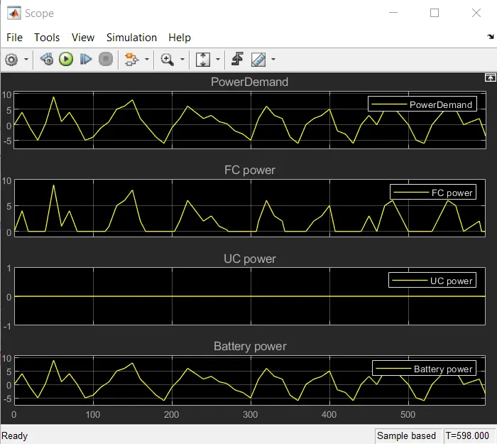
Then the negative power is completely used by battery for charging.
If SOC_UC<0.35,SOC_UC=0.3,SOC_batt=0.6
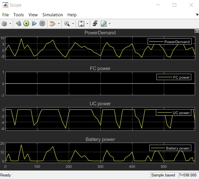
SOC of UC is less than minimum value then the peak load cannot be met by ultracapacitor,so battery is used to deliver the peak load and negative power is used to charge the ultracapacitor.
If SOC_UC&SOC_batt<0.35 both are kept at 0.3
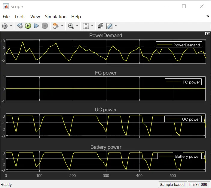
SOC of both UC and battery is less than the minimum value of 0.35 then the total power demand is delivered by fuel cell.
Conclusion: SInce we have modelled the energy management ssytem and dicussed for different conditions