Week -2
- Make a Simulink model of Doorbell using solenoid block with the following details: SIMULINK:
Simulink is a model based design language. It will test and verify for the applied input and gives the result by doing simulation using the MATLAB for each step.
Model of doorbell using solenoid figure
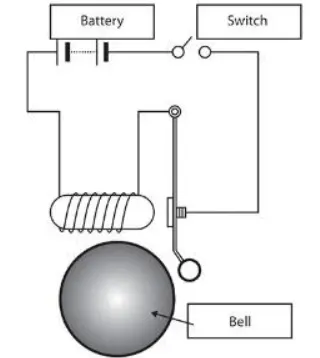
In this figure we have battery,switch,solenoid,metal arm and bell.
The operation of this figure is:
*When the switch is open the battery does not produce the energy,bell is not contact with the metal arm means it is not producing any sound.
*When the switch is closed the battery produces the energy ,electromagnetic power recieves it and then it made to pull the metal arm to hit the bell, now it will produce the sound.
Create a situation where the switch is closed for 2 seconds and then released. Observe the physical movement of the plunger.
REQUIRED BLOCKS ARE:
1.Pulse Generator
2.Switch
3.Battery
4.Solenoid
5.Electrical reference
6.Mechanical transational reference
7.Ideal transtional motion sensor
8.Solver Configuration
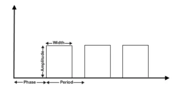
1.Pulse generator: This block , the name itself says it generate a pulses at regular intervals of time.This waveform parameters are amplitude,period, pulse width and phase delay. According to this parameters value the waveform will be produce like the below figure.
2.Switch: The switch block is controlled by the external physical signal if the PS is greater than the value specified in the parameter, then the switch will be closed or else the switch is open.
3.Battery: The batter produces energy whe the switch is closed.The negative terminal of the battery connected to the electrical reference and positive terminal of the battery connected to the switch.
4.Solenoid Block: This block is connected between the switch and the battery,this forms an a electrical circuit. In this block the spring constant parameter is set to 0 when the spring effect is not need.Port C is connected to the mechanical transational reference and Port R is connected to the ideal transational motion sensor.
5.Electrical Reference: Each model should connect to the ground i.e electrical reference for every electrical elements in the model.
6.Mechanical transational reference: Every mechanical elements in the model it has to be grounded i.e mechanical transational reference ,if the reference rotational then it is a rotational reference.
7.Ideal Transational motion sensor: When we have to apply the force to the block in the model ,it measure velocity or displacement in this model we observe the movement of the plunger. Port R is connected to the Solenoid and other is to the mechanical transational reference.
8.Solver Configuration: This block solves each equation in the model.
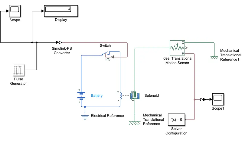
This is a simulink model of the doorbell using solenoid.
Simulation:
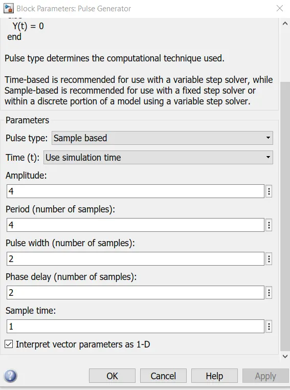
In this first we have to set the parameters of the input i.e Pulse generator as shown below
When the pulse generator fed input to the switch through simulink to external physical signal converter ,if the value of the physical signal is greater than the threshold value then the switch is closed,at this time the battery produces an energy interms of electromagnetic force in the solenoid then it produces a sound ,this plunger movement is observed by the ideal transational motion sensor then it is given to the solver configuration to solve equations of all the blocks in the model then it is given to the scope to see the simulation result.
As per the condition given delay of 2sec, when we run a simulation at that time the pulse will generate after 2sec this we can observe in the graph.
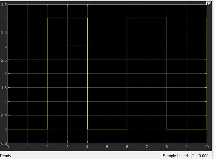
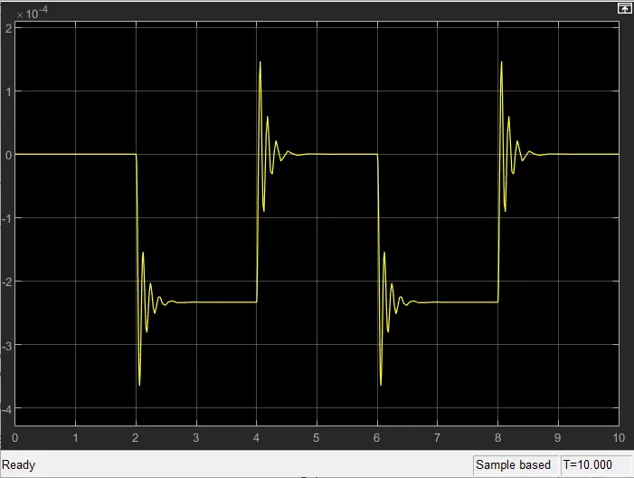
Conclusion: According to the input delay of 2sec,in the pulse generator to open and close the switch.When the switch is closed, the battery produces a energy which in turn electromagnetic power in the solenoid ,the plunger moves from port R to C,it hits bell and produces a sound.
This plunger movement is observed in the ideal transational motion sensor,to display the output it has to be connected to the scope,here we can observe the simulation output.
By reducing the spring value and increasing the damping value ,we can reduce the vibrations in the model.
2. Use a thermistor to sense the temperature of a heater & turn on or turn off the fan as per below conditions:
Temperature source: 20 °C from 0 to 10 seconds, 27 °C from 10 to 30 seconds, 23 °C from 30 to 50 seconds
Fan conditions: ON if the temperature above 25 °C, OFF otherwise
Thermistor:
Thermistor is a device used to measure the temperature. The name itself says thermal and resistor is a thermistor.It's working is based on the relation between the temperature and the resistance.The output of the thermistor is in the form of volatage or current.In the simulink model thermistor has a positive temperature co-efficient.So the resistance of the thermistor increase or decrease with respect to temperature.
Aim:
To create a simulink model of thermistor to sense the temperature of a heater and turn on or turn off the fan.
Conditions :
Temperature source: 20 °C from 0 to 10 seconds, 27 °C from 10 to 30 seconds, 23 °C from 30 to 50 seconds
Fan conditions: ON if the temperature above 25 °C, OFF otherwise.
Required blocks:
1.Signal builder
2.Controlled Temperature Source
3.Thermistor
4.Resistor
5.Voltage Source
6.Battery
7.Switch
8.Scope
9.Display
Simulink Model: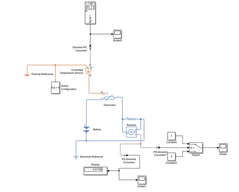
Signal builder:
In this block,we will give the input values according to given conditions.
according to the conditions we will assign a inputs are:
Here for 1 and 2 points i.e from 0 to 10sec is 20 degree C first we have to convert it into the
kelvin,so 20+273 is 293K
At point1:Time 0sec,temperature is 293K
At point2:Time 10sec,temperature is 293K
From 3 to 4 points i.e from 10 to 30 sec is 27 degree C is 27+273 is 300K
At point3:Time 10sec,temperature is 300K
At point4:Time 30sec,temperature is 300K
From 4 to 5 point i.e from 30 to 50 sec is 25 degree C is 25+273 is 298K
At point5:Time 30sec,temperature is 296K
At point6:Time 50sec,temperature is 296K
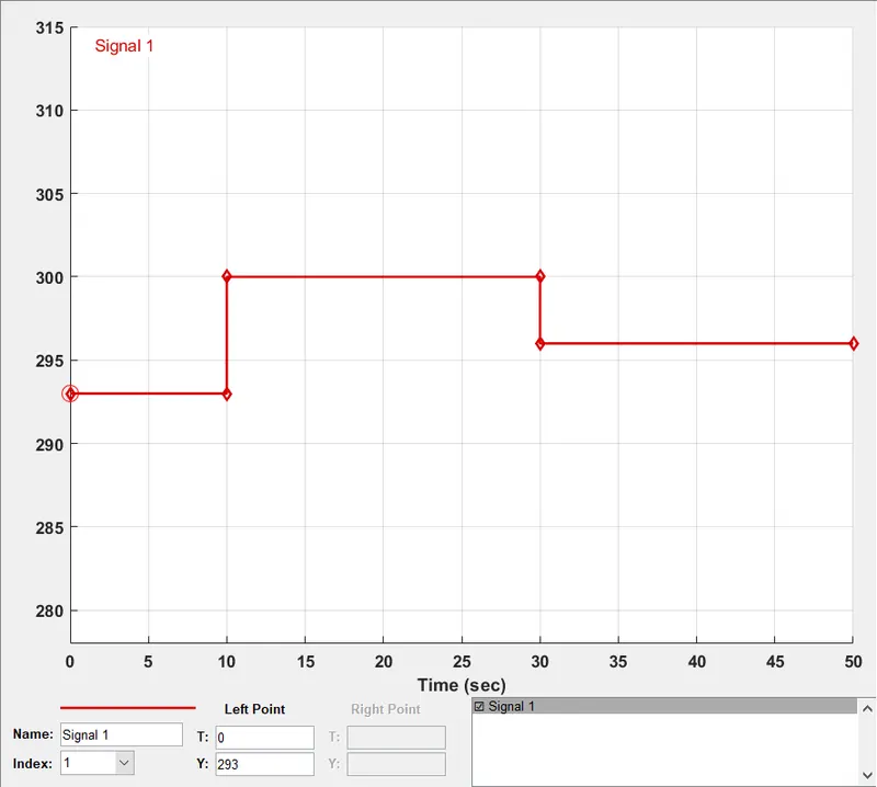
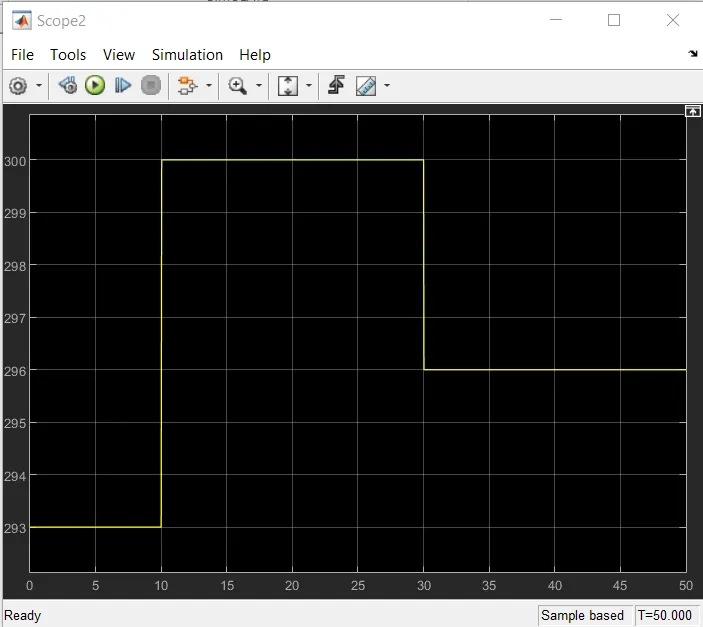
this is seen through the scope block after input given to the signal builder.
Controlled temperature Source:
This block represents an ideal source of thermal energy ,this energy is powerful to maintain specified temperature difference across the source regardless of the heat flow consumed by the system.
Thermistor:
It is a type of resistor whose resistance is dependent on temperature.This block represents an NTC thermistor using the B-parameter equation.
NTC-Negative temperature co-efficient
Resistor:
The resistor block models a linear resistor,described with the following equation:
V=IR where V-volatage,I-current,R-resistance
Voltage Sensor:
The voltage sensor block represents an ideal voltage sensor , that is a device that converts voltage measured between two points of an electrical circuit into a physical signal proportional to the voltage.We will get the threshold value then it has to be enter in the switch.
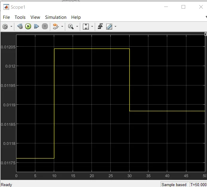
Voltage Source:
The voltage source block implements a voltage source with two terminals + and -
Electrical reference:
This block represents a ground for all the electrical elements has to be connected to the electrical ground,that is an electrical reference.
Thermal reference:
This block represents a ground for all the thermal elements has to be connected to the ground,that is an thermal reference.
Simulation:
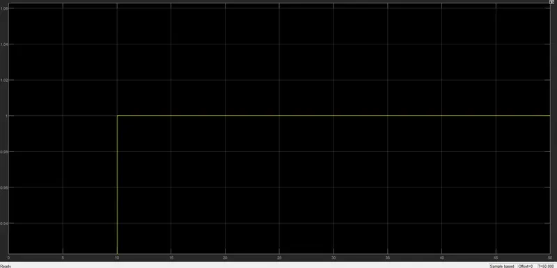
In this Simulation ,the input is given to the signal builder as per the given condition in the above.Then it is given to the controlled temperature source,here it is maintain the temperature differ without considering the how muh heat is produced in the system.Then is given to the thermistor,here the input temperature flows through this block,thermistor is connected with the resistor and see that the current is flowing from positive to negative terminal hence the resistor is positive.By this we can see ,connect the positive terminal of the voltage source to the positive terminal of the thermistor and negative terminal of voltage source to the negative terminal of the voltage sensor and the resistor to get the values from the voltage sensor here it is then connected to the PS to simulink converter then it is given to scope and display in this display we will get the voltage that has to be enter in the switch i.e threshold value then the switch will do the function as if the value is greater than the threshold value then it will be switch to 1 or otherwise is switch to zero.Here we can see the condition of the fan is on for the temperature above 25 °C and it is off for the temperature below 25 ° C through scope.