Week 9 Challenge
Solution:
Energy Management Stratergy:
- An energy management strategy involves optimizing the usage of each energy storage component based on various factors such as power demand, efficiency, state of charge (SOC), and driving conditions.
- Power Demand Analysis: Continuously monitor the power demand of the vehicle, taking into account factors like acceleration, deceleration, and cruising speed.
- Understand the specific characteristics of each energy storage component:
-
- Battery: Offers high energy density but may have limitations in power delivery.
- Fuel Cell: Provides high power output and longer range but may have slower response times compared to batteries.
- Ultracapacitor: Offers high power density, quick charging, and discharging capabilities but with lower energy density compared to batteries.
- During acceleration and high power demand situations, the ultracapacitor and/or fuel cell can provide the required power boost due to their high power capabilities.
- During cruising or low power demand situations, the battery and/or fuel cell can operate efficiently to maintain SOC and extend the range.
- During braking or deceleration, regenerative braking can be utilized to recharge both the battery and ultracapacitor.
- Maintain the SOC of each component within optimal operating ranges to maximize efficiency and longevity.
- Prioritize charging or discharging of each component based on its current SOC and power demand.
- Adjust energy flow dynamically based on real-time feedback from sensors and vehicle systems.
By integrating these principles into the energy management strategy, a hybrid electric vehicle can achieve optimal performance, efficiency, and reliability while leveraging the unique strengths of battery, fuel cell, and ultracapacitor technologies.
Power flow:
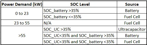
Power sharing stratergy
Simulink Model:
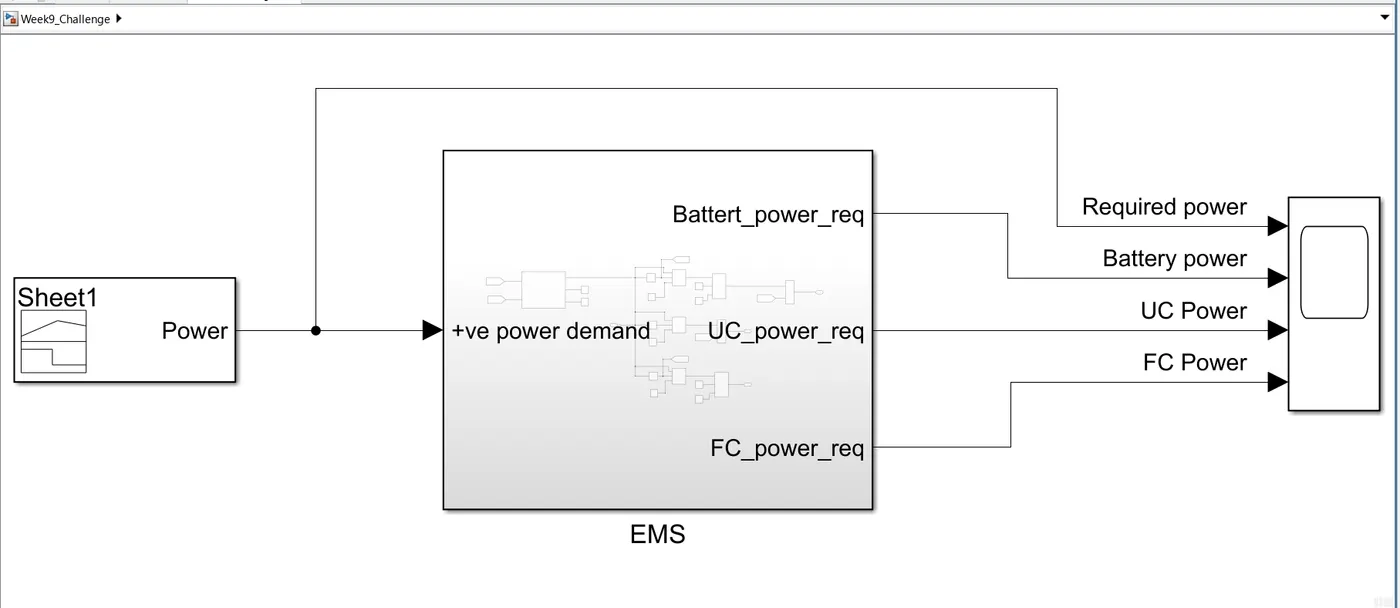
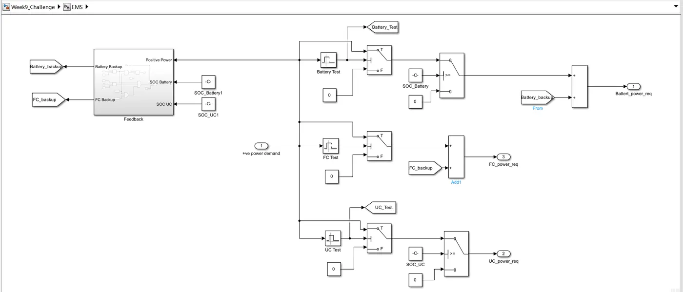
- The power demand generated by signal builder block is fed as an input to the EMS subsystem, where the power demand and the SOC level of battery and ultracapacitor is analysed to select the component (battery or fuel cell or ultracapacitor) that will provide the required power.
- Inside the EMS subsystem, the power level is checked usig the interval test block.
- If the power demand is less than 23kW, the SOC level of battery is checked and if the SOC is greater than 35%, the required power is provided by the battery.
- If the power demand is between 23kW to 55kW, the power demand is provided by the fuel cell.
- If the power demand is more than 55kW, and the SOC level of ultracapacitor is greater than 35%, the required power is provided by the ultracapacitor.
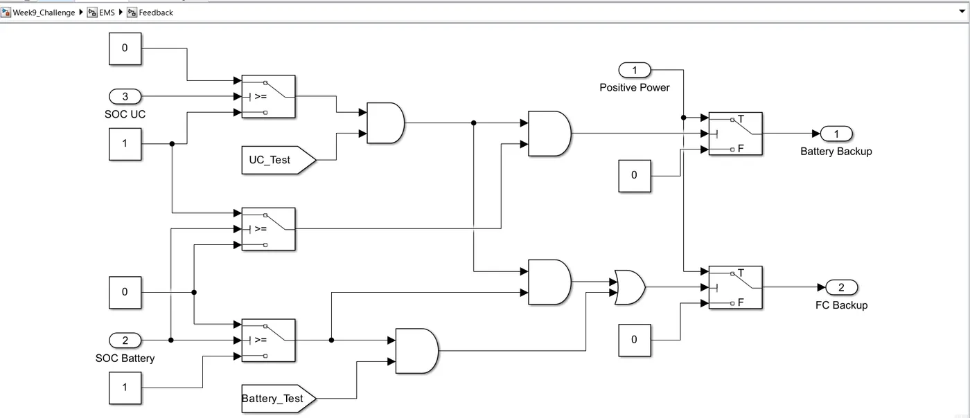
- Feedback subsystem is used to decide the power supply source if the SOC level is less tahn 35%.
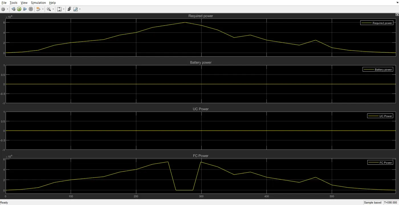
- When the power demand is less tahn 23kW and the battery SOC is less than 35%, the required power is provided by fuel cell.
- When the power demand is more than 55kW and the SOC of ultracapacitor is less tahn 35% but the SOC of batery is more than 35%, then the required power is provided by battery, if the battery SOC is also less than 35%, then the required power is provided by the fuel cell.
- The simulation is run for 598 sec with different SOC conditions of battery and ultracapacitor and teh results are provided below.
Result Screenshot:
SOC_Battery = 0.7; SOC_UC = 0.45
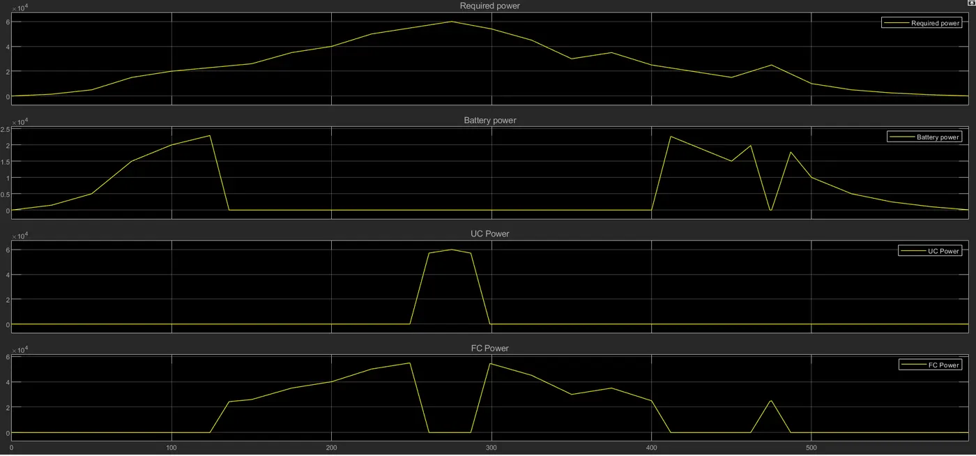
SOC_Battery = 0.15; SOC_UC = 0.75
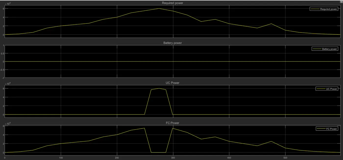
SOC_Battery = 0.65; SOC_UC = 0.2
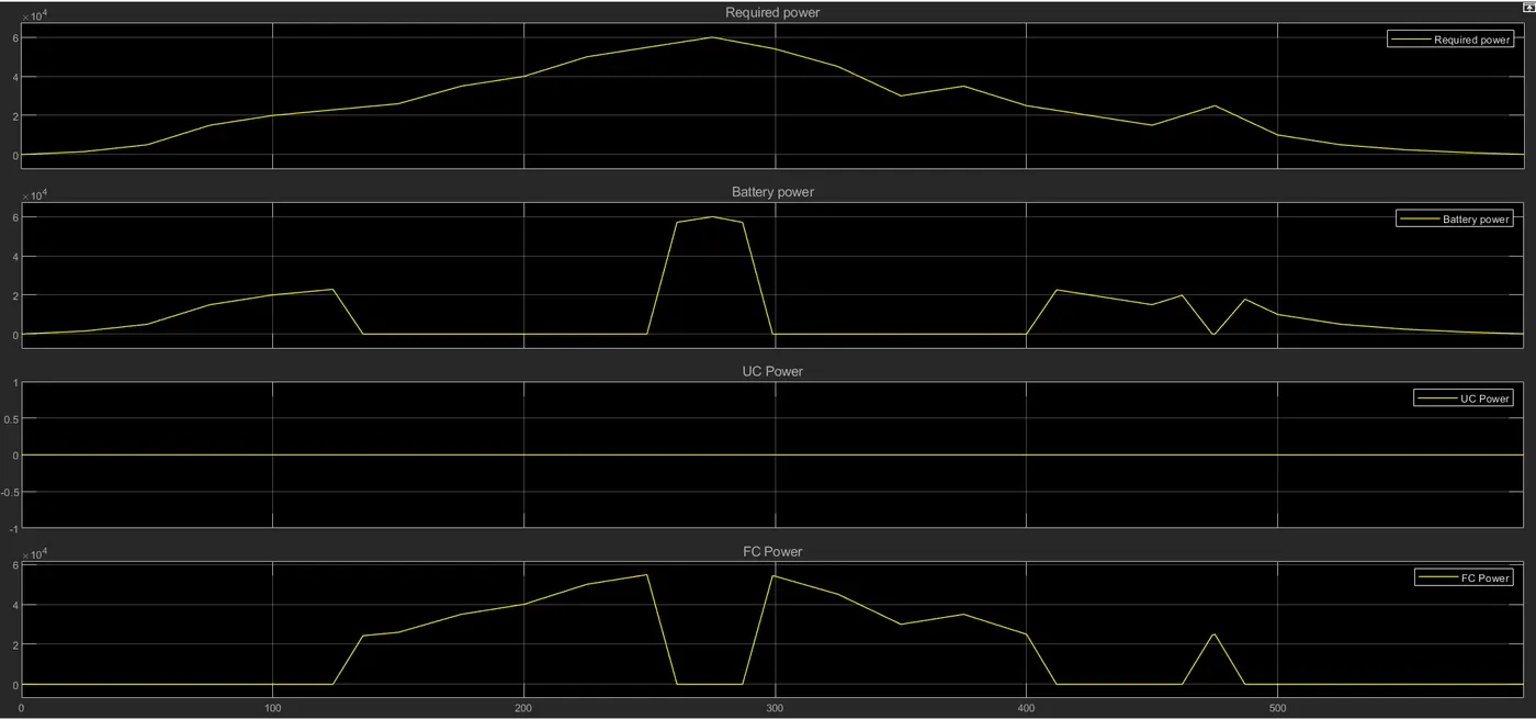
SOB_Battery = 0.15; SOC_UC = 0.05
Conclusion:
The energy management strategy model with battery, ultracapacitor and fuel cell for the positive power is simulated for various SOC conditions. The power demand is distributed between battery, ultracapacitor and fuel cell as per the conditions specified.