Week 9 Challenge
MOLD DESIGN, SLIDER & INSERTS CREATION FOR CPU FAN CASE USING SOLIDWORKS
In this report mould design and creation of sliders for CPU fan case was done by creating each individual part in assembly workbench following step by step process to attain best results.
As there was the necessity of the sliders for the model, we should create washers and locking mechanism for the sliders.
Assuming the material for the model as ABS (shrinkage - 0.6%), the scale value is determined as (0.6/100) + 1=1.006 for the model.
MODEL
The steps followed and commands used for the core and cavity blocks creation are:
MOLD TOOLS
Mould Pull direction:
The direction in which the core moves apart from the mould, Based on the models and the features in the model the direction of pull is determined
Draft Analysis:
Analyse draft angles of faces based on mould pull direction for moment of core and cavity blocks.
Some region shown in yellow do not have adequate draft we should inform product design team to provide adequate drafts.
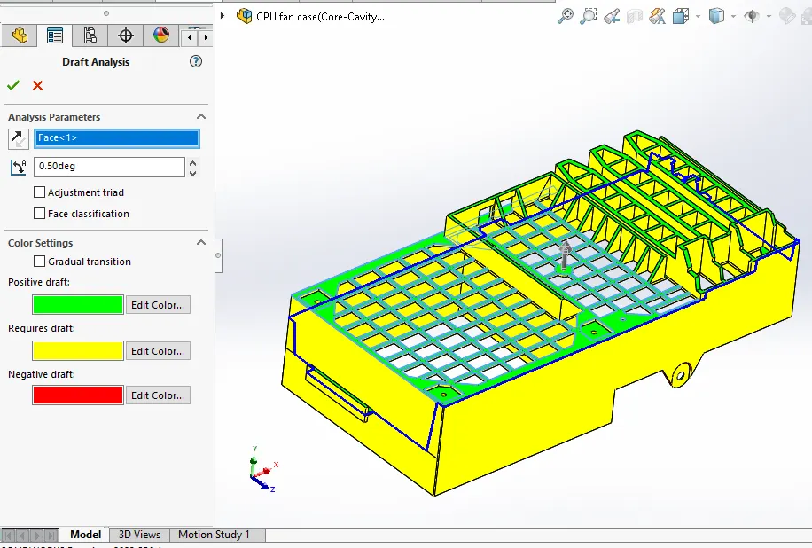
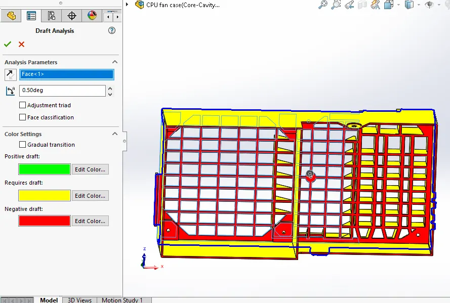
Draft Creation:
The minimum draft should be 0.5 degrees, if there was no draft certain draft will be provided to the component.
Scale:
Scales the model by a specified factor based on the material provided (Shrinkage factor)
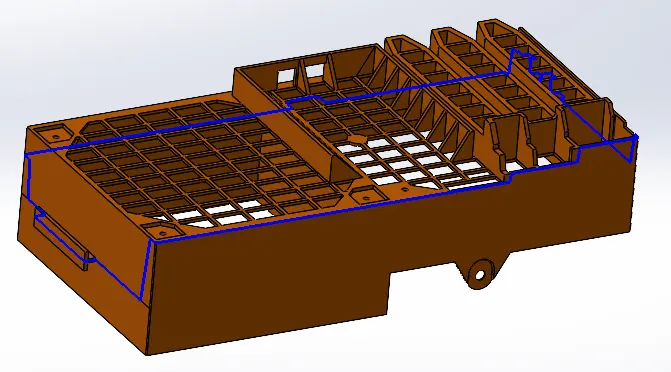
Parting Line:
Parting line separates the core and cavity surfaces. Parting line created in such a way that it avoids or as minimum number of undercuts and also matching draft provided so that there is no 90 degree edges which avoids rubbing of core-cavity blocks.
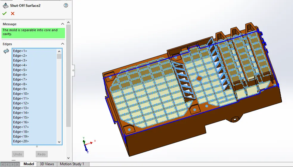
Shut off Surfaces:
Create mould shut off surfaces, it prevents the flow of injected material by creating shut off surfaces. Shut-off surfaces created such that maximum features are included in core side.
Parting Surface:
Create parting surfaces between core and cavity surfaces.
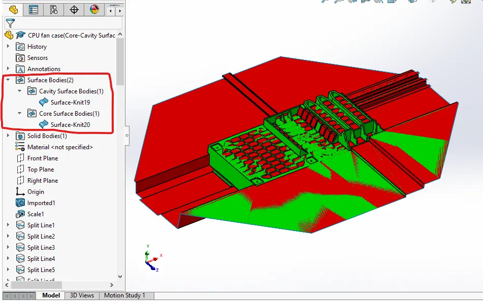
Core & Cavity Blocks:
The Core and cavity block are created as individual parts in assembly by inserting the component as Core and cavity surfaces created for CPU fan case. The sprue location will be adjusted by rotating and giving mates with the planes of assembly.
Core
The core block is created using the core surface created and there will be 2 blocks internal and external block which are created considering the minimum distance between mould and the outer edge and the base of slider these two blocks are due to the parting line not on the same plane and combined these two blocks act as single core block.
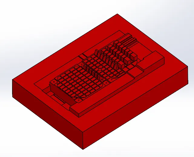
Cavity
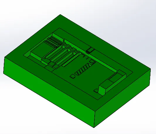
The cavity block is created using the cavity surface created and there will be 2 blocks internal and external block which are created considering the minimum distance between mould and the outer edge and the base of slider these two blocks are due to a curvature in parting line parting line not on the same plane and combined these two blocks act as single cavity block.
During mould design of CPU fan case in the step of draft analysis we can clearly observe an undercut is present, to optimise the undercut sliders will be used.
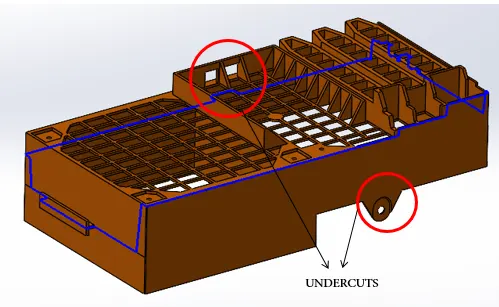
Slider direction will be perpendicular to the direction of the pull which will be horizontal and these are separable from the core and cavity blocks as the sliders are movable, they should have a base for the movement form the model we can easily provide a base while creating the blocks itself.
The commands and steps involved in the creation of slider are:
SLIDER CREATION:
The commands used for creation of sliders are:
REFFERENCE PLANE:
This command is used to create a plane, axis.
SKETCH:
Using this command, we can create a new sketch.
CONVERT ENTITIES:
It is a tool available in sketching workbench to project the sketch selected on the plane you are sketching and in this tool another option of intersection curve is there which is also used to project sketch.
SPLIT:
It is available in features tab used to split the body in two pieces along the sketch based on applications.
FILLETS
It is used to make fillets to edges of solid bodies.
RECTANGLES:
It is also an entity used and available in sketching workbench to create a rectangle of different types like corner rectangle, centre rectangle, 3- point corner rectangle, 3-point centre rectangle and parallelogram based on their applications.
CUT EXTRUDE
It is available in features tab used to remove material from a solid body along the sketch in which direction, we need based on applications.
EXTRUDE BOSS
It is available in features tab used to add material from a solid body along the sketch in which direction, we need based on applications.
MOVE FACE
It is available in mould tools tab used to move faces of a solid body.
MOVE/COPY BODIES
It is available in mould tools tab used to moves, copies and rotate solid and surface bodies.
COMBINE
It is available in mould tools tab used to add, subtract bodies.
DELETE/KEEP BODY
It is available in mould tools tab used to keep or delete a solid body or surface body.
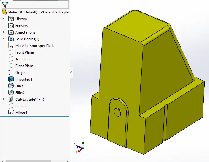
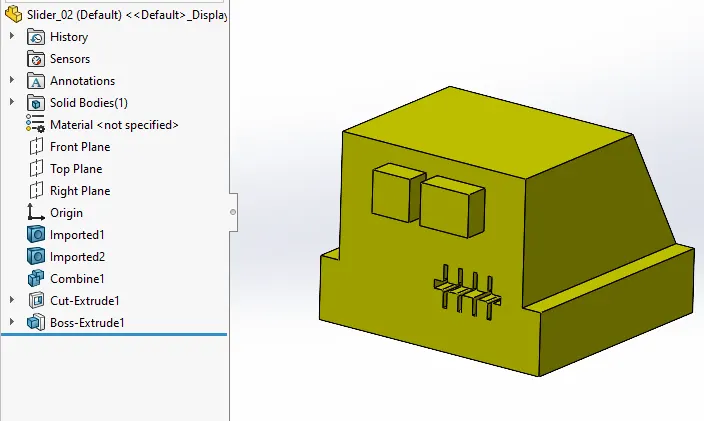
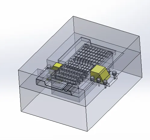
The sliders are created using the split option making the sketch as the profile of the undercut and the plane on which sketch is made.
These sliders are modified such that washers and locking mechanism will be correctly designed.
The core and cavity blocks are modified according to the shape of the slider after all modification using the combine command.
Collar width-5mm
5mm for collar of slider were washers and slider collar touch.
FINGERCAMPIN:DISTANCE OF WEDGE SHOULD BE 40MM TO ACCOMODATE FINGERCAM PIN.
height of wedge should be 2/3rd of its length vertically.
Core-Cavity Block After Edits with Sliders:
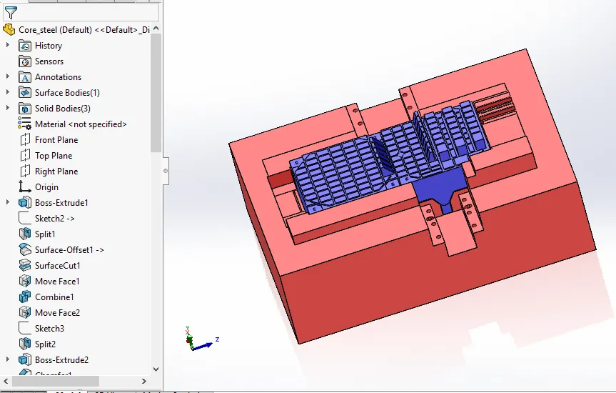
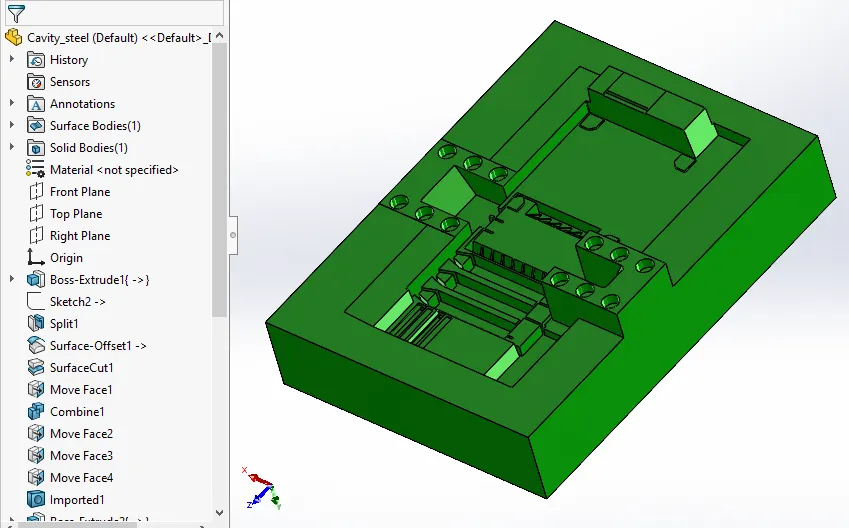
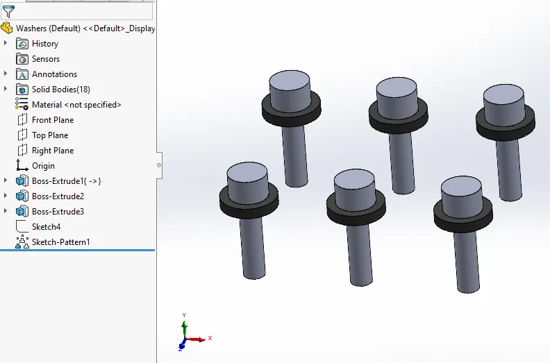
Washers and bolts are designed beside the slider base for this separate space is assigned on the blocks while modifying the blocks after slider design.
INSERTS CREATION:
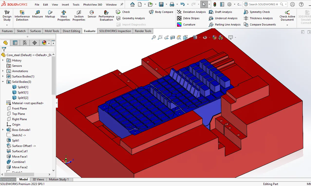
Inserts are used when the machining of the blocks are very tough to make to make this easier insert will be placed where the machining of the block will be tough by creating the split of the blocks.
THIN RIBS- 1mm diameter cutter can only cut to a depth of 20mm(if a rib as width around1.005 and depth of 30mm tool cannot cut the rib since depth of cut is high).the solution is to make inserts.
insert for mould can be manufactured separately and inserted into main mould block and then together they function as the core block.
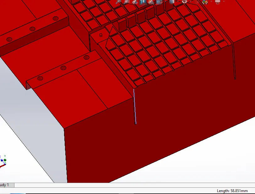
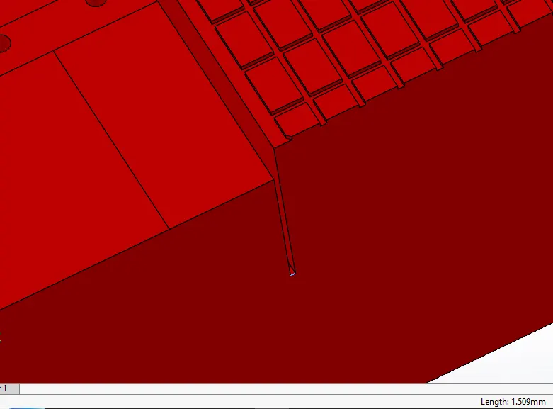
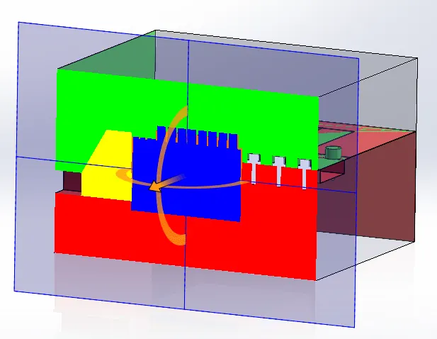
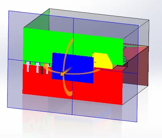
In the above image we can clearly observe the blue surface which is selected is the minimal space and of large depth where no tool can be machined such types, so here we will create inserts.
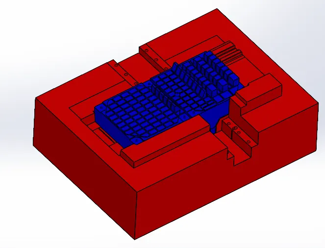
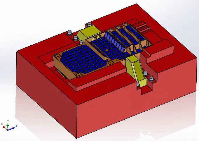
In the above image the inserts are blue in coloured these are designed in such a way that they can be easily inserted and can be removed based so the machining process will become easier.
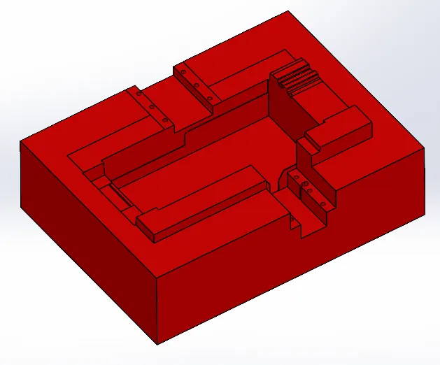
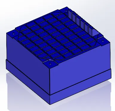
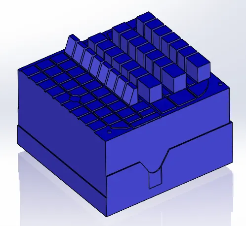
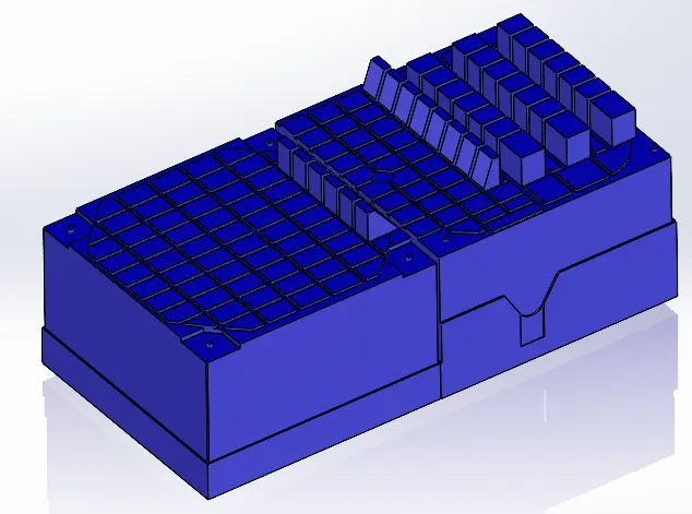
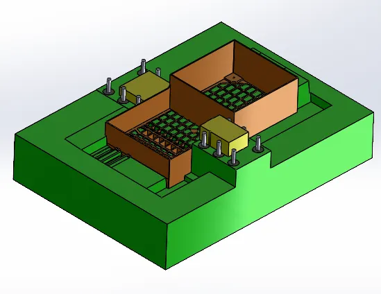
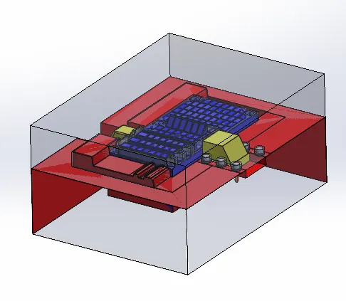
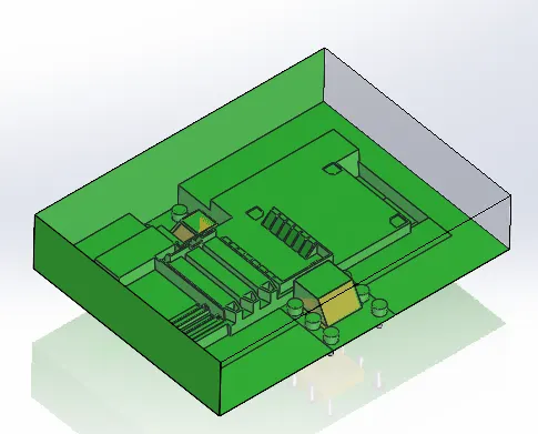
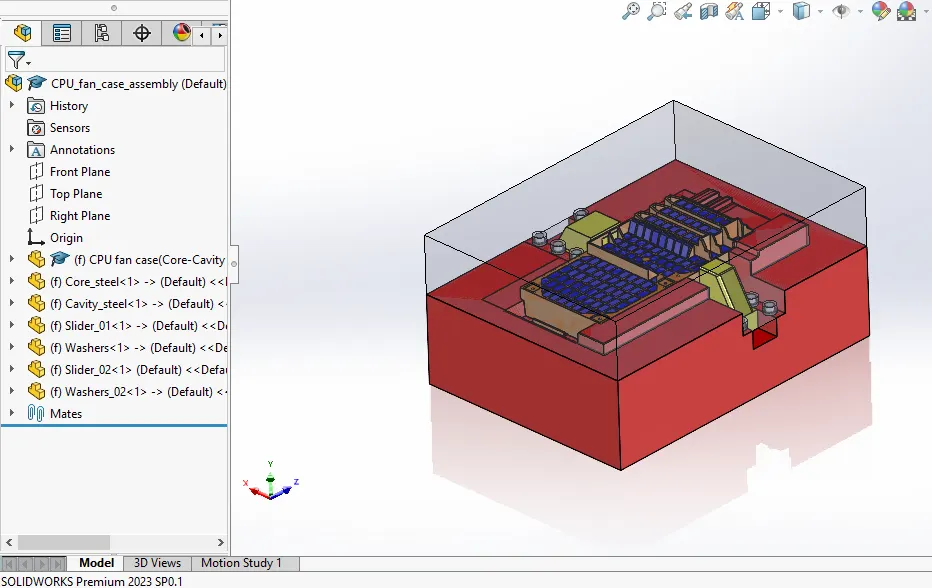
The final assembly of the model after creation of sliders inserts and washers for clamping.