Door Arm Rest Week 8 Challenge
Procedure To Create Class-B & Class-C & Draft Analysis of Door Arm Rest
Step -1: - check the Class-A surface for all joints are connected properly if any surfaces are required to join use the join tool in Join- Healing toolbar or use the Boundary command in the Extract toolbar
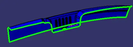
Step -2: - Check component in all 3 Axis the component. In which direction component can clear all the features in the tooling axis. In my case, I assumed Z-Axis is the tooling direction. And check the line Bisection method for 1 side and other side use sketch as the line and give some an angle of 30 and create a tooling axis for the component and use the line command and create the line using bisecting option and create a tooling axis of the component in the Z-axis.
Step -3: - Check the component Tooling axis of the component and the side surfaces are visual then the Tooling Axis is correct this is for the class -A surface ones all the component was created then if any changes are required, we can adjust from there Tooling Axis of the component was created.
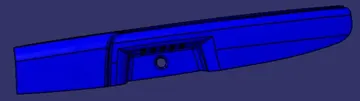
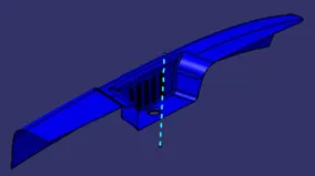
Step -4: -create the geometry set and name as Constructions For Class B & C Surfaces add the Tooling axis to that set and Publish the class -A and Tooling axis. And insert a new geometry set and name as B-surface creating and start creating the B-surface. First, extract the top longest surface of the component and use untrim the surface and for removing the trimmed surfaces and extrapolate the surface up to 50mm that covers the A-surface. And also extract the side plane surfaces and extrapolate the surface and join the two surfaces by using the Trim command and offset the surface up to 2.5mm below the A-surface give the fillets of 14.5mm for the component. Name it as the First set.
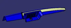
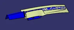
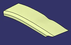
Step -5: - Repeat the same process for the other surfaces and name the surface as Second Set.
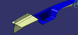
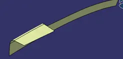
Step -6: - To make a side connecting curved surface draw a point on the center and set the axis on the point and draw a sketch in the sketch draw a line that connects the two surfaces and exit the sketch and use multiple extracts and select the curved part and make it as a curved sketch and then use Swept command use first option reference with surface select the sketch and smooth curve and select ok surface was formed and use the offset command offset the surface p to 2.5 mm below the A-surface.
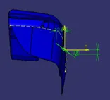
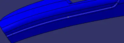
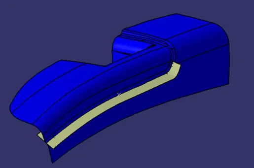
Step -7: - And extract the connecting surfaces of the swept surface and extrapolate the surface and give an offset same as above and draw a line with some angle and connecting from top fiber to bottom fiber. And split the excess surface and use a blind tool for connecting the swept surface and connecting surface. And adjust the line that matches the a-surface. at the end join the two surfaces.
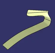
Step -8: -for creating the side core parts extra the surfaces and untrim the surface and extrapolate the surface and trim the extra portions and add final fillets for the surface
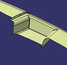
Step -9: -use extrapolate surface that connects the surface and surface and trims unwanted surface of first set and second set and add fillets to the final surface at the end name the file as B-surface.
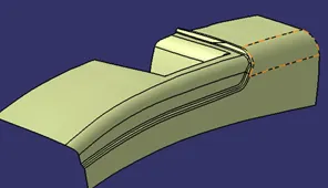
Step -10: - Start creating the C-surface start with multi-extract and smooth curve command of the bottom surface and use swept command and extract the bottom surface. And repeat the same process for the side surfaces to extract the curves use the boundary command and swept the surface.
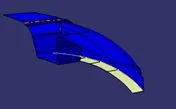
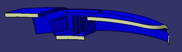
Step -11: -to get the connecting curved surface use the blind and multi-section curve and add the connecting surface for the c-surface and join all the surface with A-surface and name as Final C-surface.
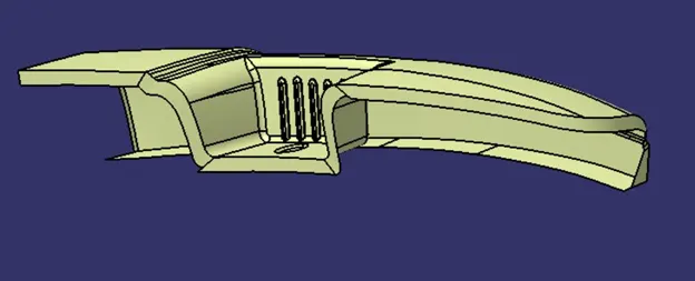
Step -12: - at the final step Trim the unwanted extra surface from the c surface with connects to B-surface.
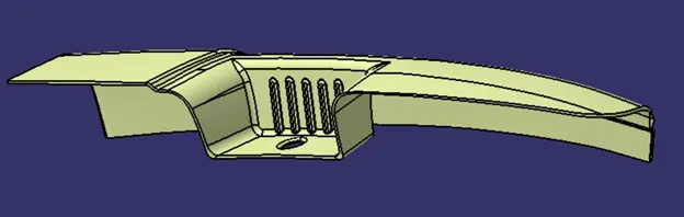
Step -13: - add the thickness to the final trim by using a Closed surface from the Part workbench.
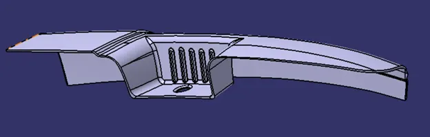
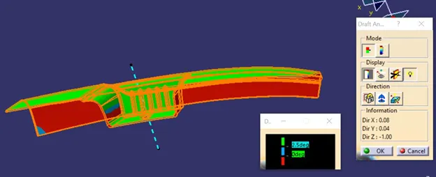
Step -14: - the next step is the Draft analysis of the component for that go to insets and Analysis to Feature draft analysis. Draft analysis interface will open and use compose option and select the UCS and fix the axis to the component. And check the draft position correct or not if it is in the wrong direction change to inverse the draft direction. If any changes are required for the changes in the walls Draft angle adjust the sketch to get the perfect Draft angle. Hence the final part was completed with solid features and Draft analysis.
Note: -For my component having some Class -A issue for that reason in some parts are getting lower thickness and draft analysis issues. In that case, we need to inform the issue to Class -A surface team to solve the issue.