Week 9 - Challenge 2 - Switch Bezel Design
ANSWER
AIM
To perform draft analysis and make a solid model from the given class A input.
TOOLING AXIS CREATION
- Dispatch the CAT component file.
- Before to clicking join, inspect surfaces for gaps, and then click preview.
- select the proper tooling axis so that no material will interfere and all the elements can be produced.
- Using the surface at the bottom as a starting point, design an axis system.
- the class a surface walls and the yz plane must intersect.
- Make a line in the zx plane that is 6 degrees from the intersection.
- On the suspected drafts, cover the class A surface and draw point-to-point lines.
- The two lines should be bisected at that point to form a tooling axis.
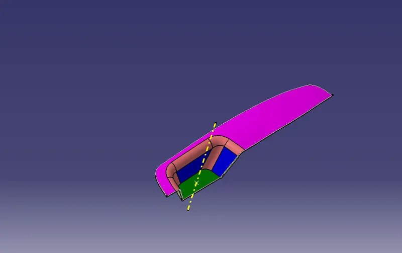
- The component's tooling axis is generated.
DRAFT ANALYSIS
- Go to customised view parameter >under mesh >tick material before proceeding to drat analysis, and then press ok.
- Go to insert >analysis>feature draught analysis to access the draught analyses.
- Set the draught direction using the compass.
- Change the draught angle on the colour scale to 3 degrees.
- As a passing draught angle is shown, the component turns green.
- Check the component's angle using running points.
- The preliminary analysis is finished.
CREATION OF CLASS B SURFACE
- Using repeated extracts, remove the surfaces from the class and untrim them.
- To trim and offset the surfaces to 3 mm to generate thickness, use extrapolate to ensure that all of the untrims are appropriately intersected.
- Using the trim command, remove the superfluous surfaces.
- Add them to the new geometric set and give it the names of the corresponding parts.
- After finishing the model's full surface, add fillets.
- The fillet value will be added to the component's thickness if the fillets are outside. For example, if the component's thickness is 3 mm and the fillet value is 3 mm, the outside portion value should be 11 mm to achieve uniform thickness.
- Trims should be carried out one at a time for clarity.
CREATION OF CLASS C SURFACE
- Utilizing boundary, separate the boundary from the class A surface.
- Utilize the sweep command, select the profile type line, subtype with draught direction, guide curve, and draught direction, and then click Preview.
- To create a clean surface and reduce the spots, use a smooth curve.
- Become a part of the class A and class C surface.
- If there are any boundaries, check them, extrapolate the class A to 0.05 mm, and then trim the material with class C.
- After obtaining the sweep, trim the output with a class B surface to obtain the desired result.
- Now make a solid of the component using the open part design workbench and a close body surface.
- Conduct a draught analysis after getting close to the body surface. Some components of the company have a 2.9 degree draught; this draught needs to be modified, and for the maian wall, the tooling axis needs to be adjusted.
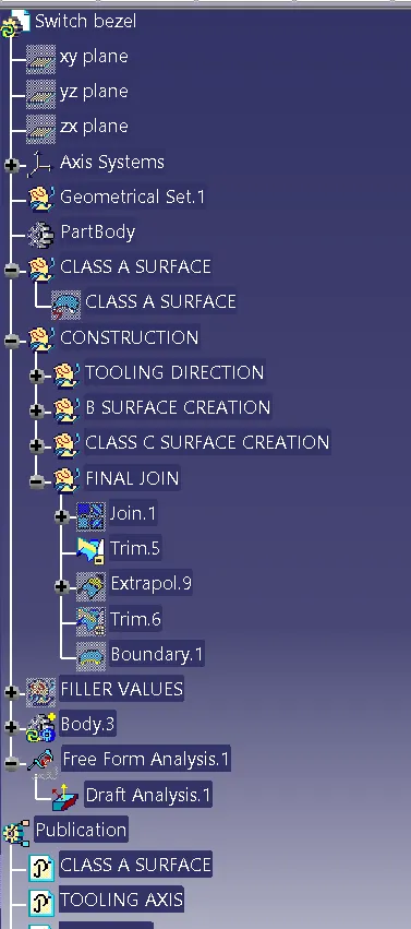
TREE STRUCTURE