Week 9 - Challenge 2 - Switch Bezel Design
Aim:
To Create the B and C - Surface of the given A - Surface of the Switch Bezel Part by considering all the manufacturing requirements.
Design Considerations:
Nominal wall thickness = 2.5 mm
Nominal Draft angle = 3°
Class A - Surface Inspection:
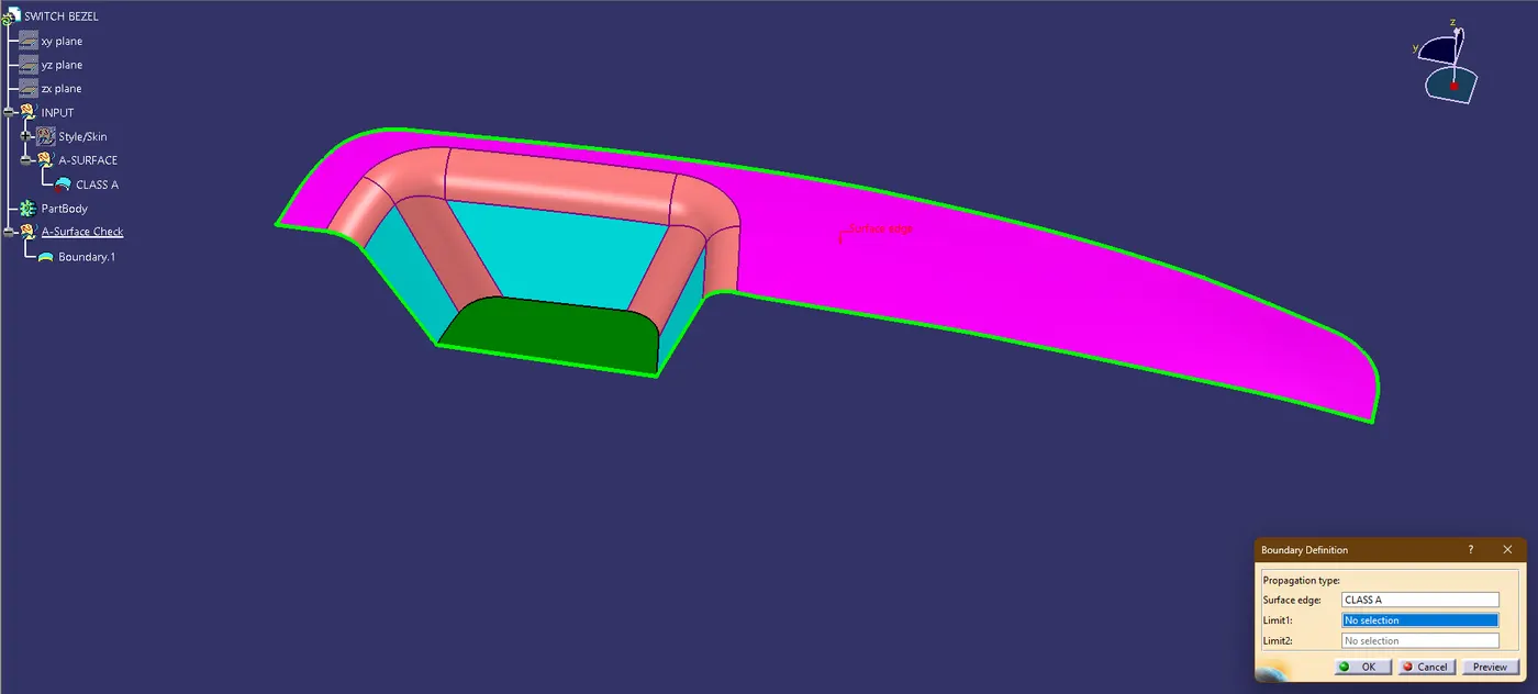
- The given A -Surface is first checked for any patch connectivity errors visually and by using join or boundary command.
- Any Changes required in patching is intimated to the styling team.
- Here boundary command and only one boundary edge is found.
Tooling Axis and Draft analysis:
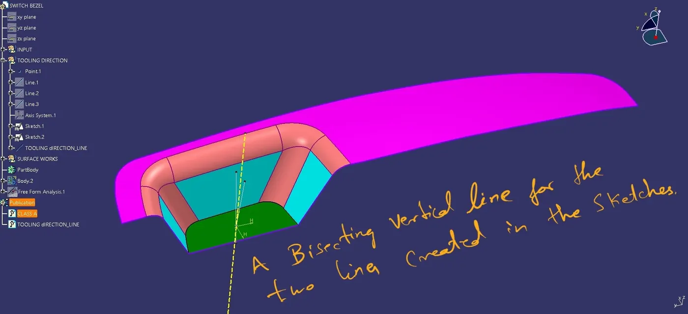
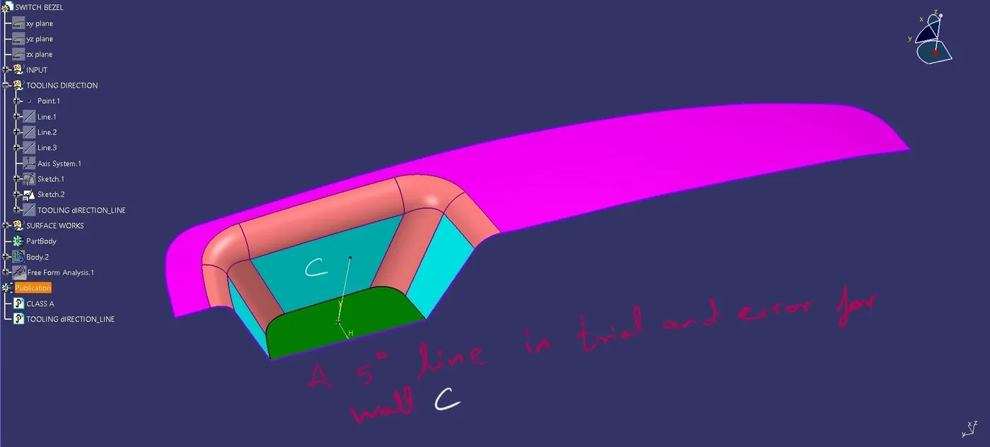
1. Two Sketches are created, and intersections are taken, and lines are created.
2. Then a bisecting line b/w the sketches is created, and a draft analysis is performed again.
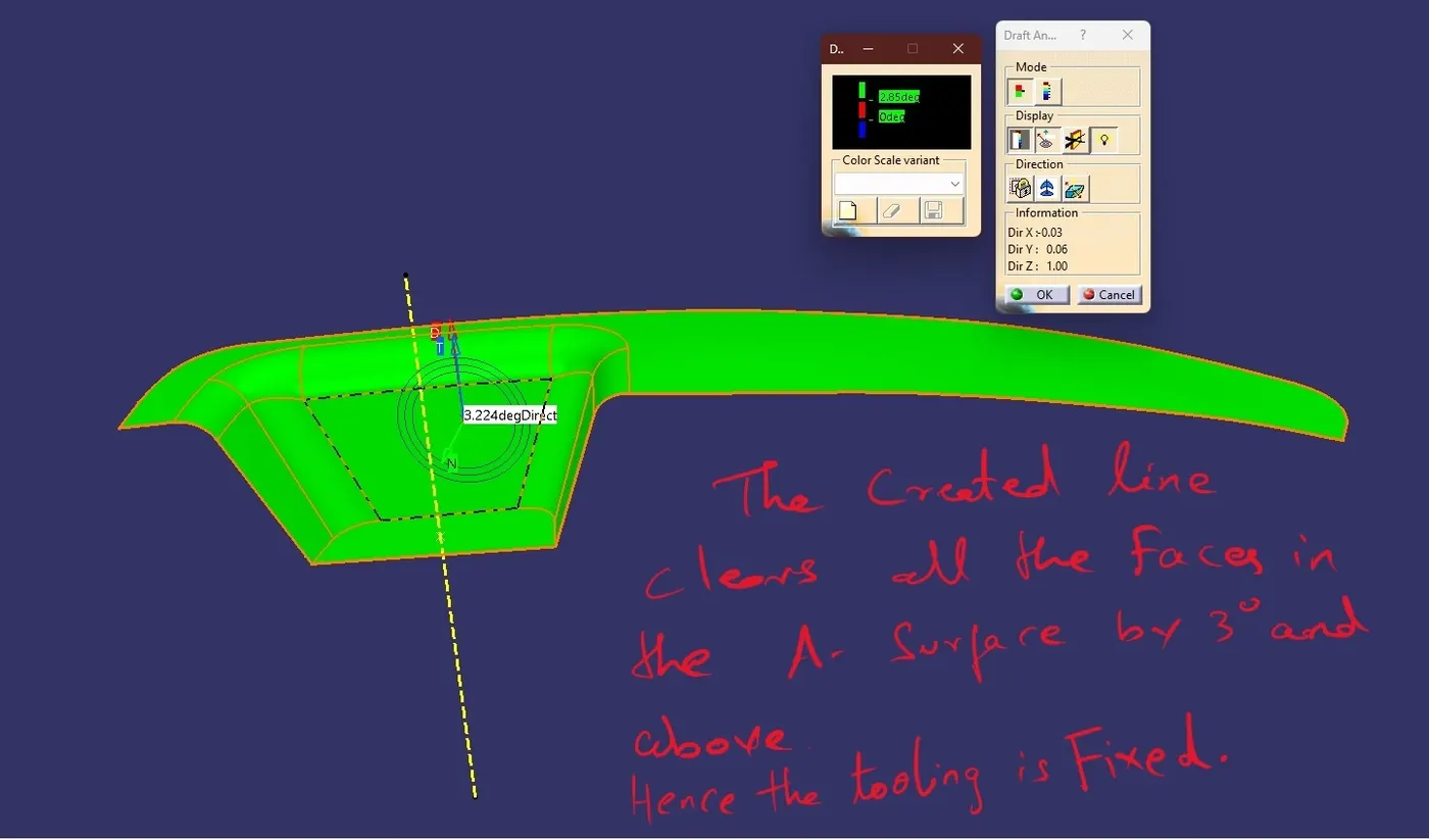
3. If the A - Surface is clearing the draft of minimum 3 then the tooling axis is fixed, or necessary modifications are carried out to clear the draft.
B- Surface Creation:
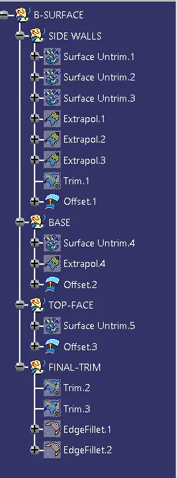
- Given that the A - Surface clears the deaf t, B- Surface is created by offsetting the A - Surface by the nominal wall thickness, which is 2.5 mm here.
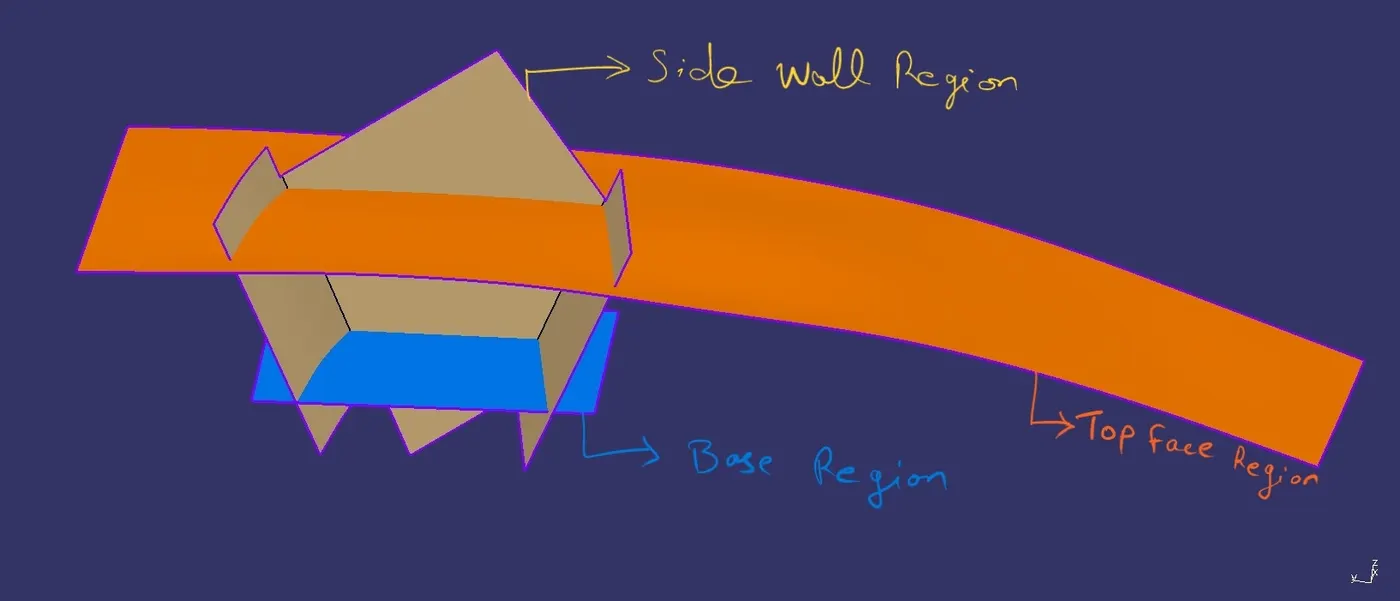
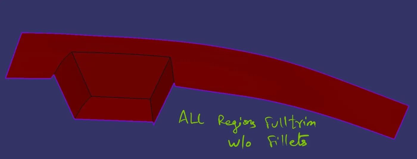
- While creating offsets, the fillets or twisted Surfaces might Cause errors if the A-surface is selected on the whole and thus making the CAD operations very complex and hence it is better to do by segregating the Surface patches into to Several Units or regions without filleted areas.
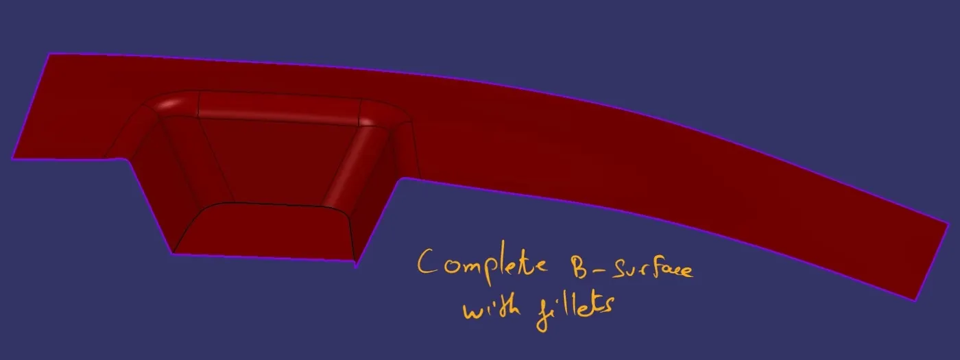
- Then the fillets are given accordingly so that the nominal wall thickness is maintained at all areas b/w the A and B surfaces.
C- Surface Creation:
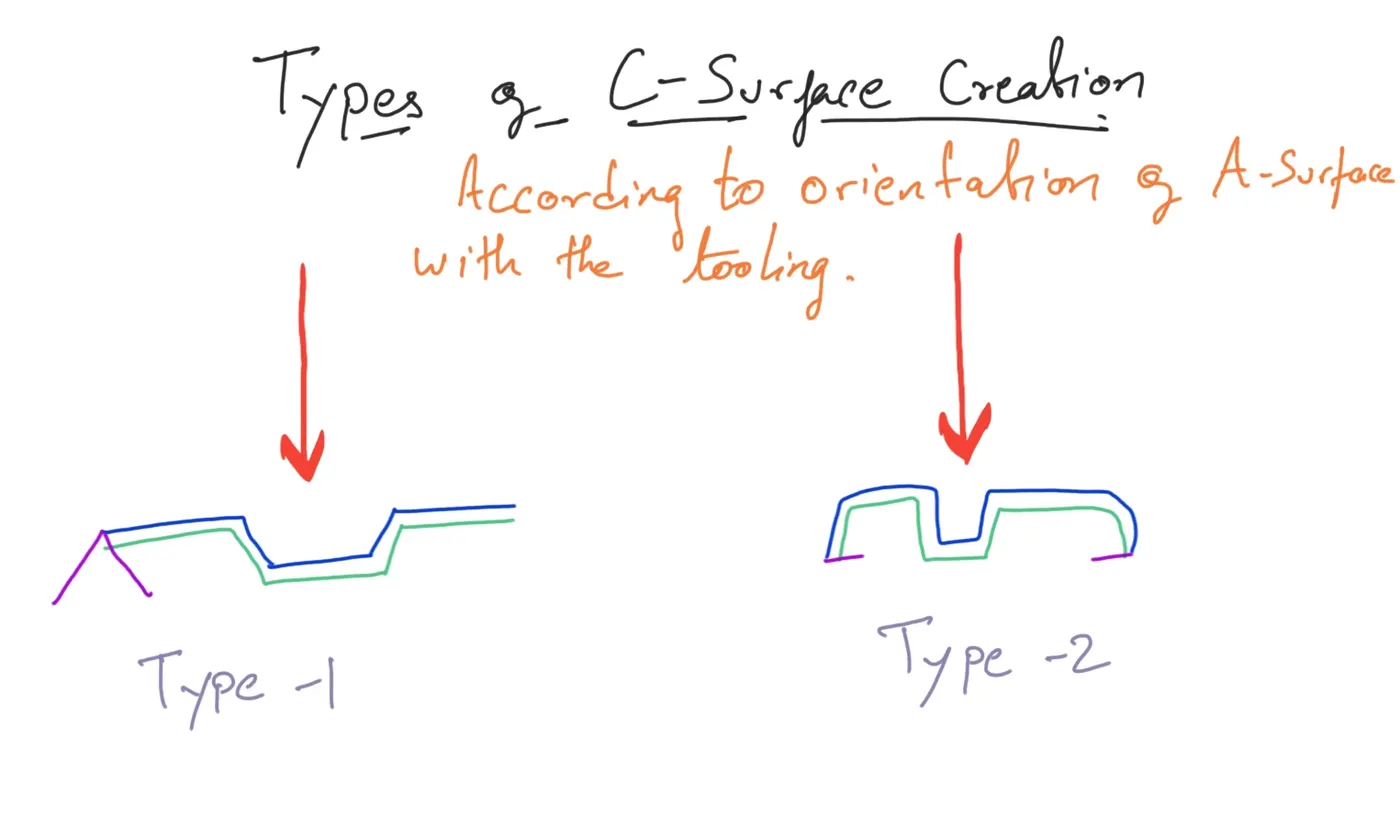
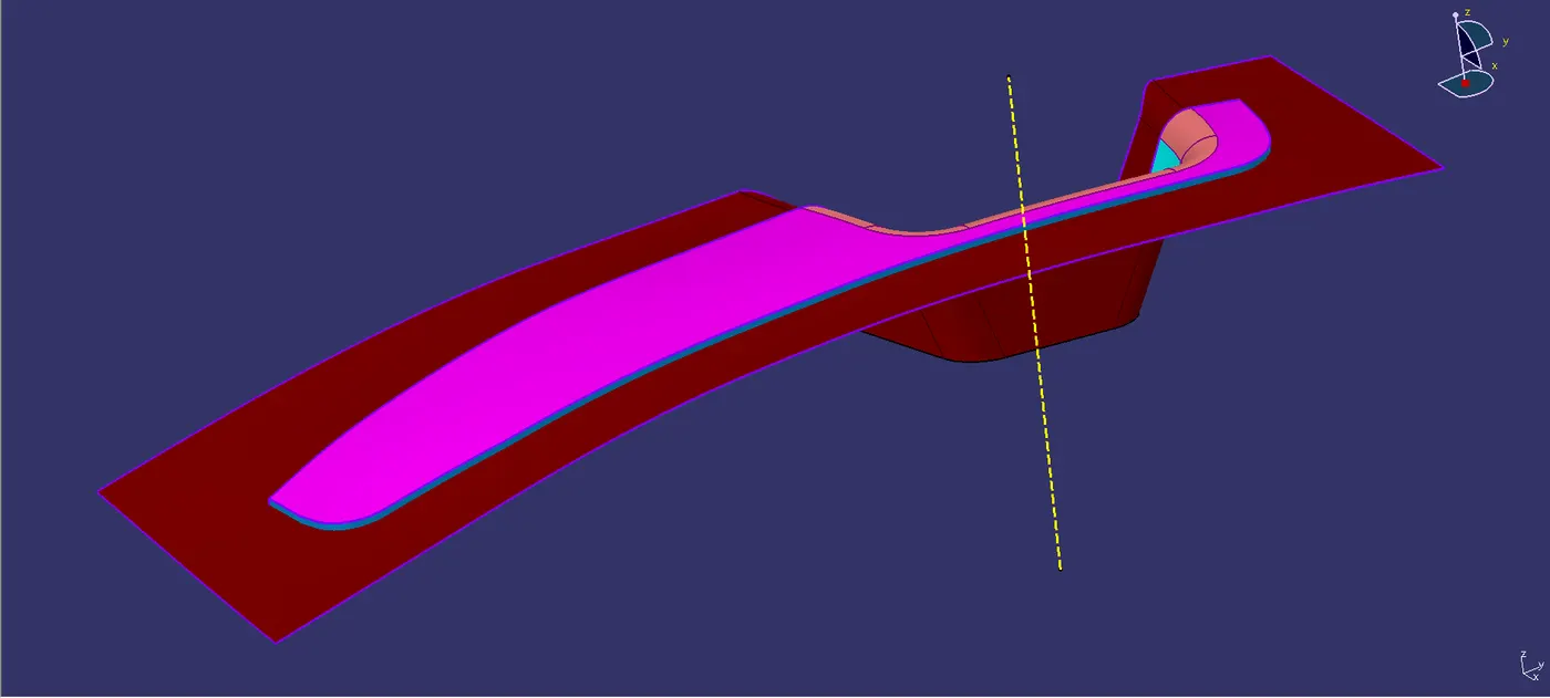
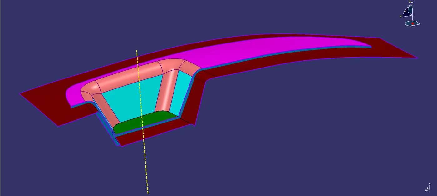
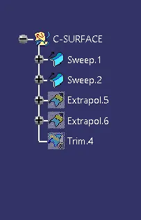
1. The C- Surface is created using the boundary of the A – Surface.
2. The C-Surface is of two types which depends on the boundary of the A-surface and its surface's nature of alignment with the tooling axis.
3. If the Surface is perpendicular to the tooling as is then the boundary is visible perpendicular to the tooling axis. Here there are
two possibilities one is an opening draft or a closing draft which is dependent on the parting line placement. If an opening draft is given
then the parting line is on the B-side of the part, on the other hand the panting line is on the A-Side of the part, when a closing draft is given.
4.This is important as the parting line defines the opening and closing of the mold halves and a molding defect called flash, where some material tends to escape from the mold at the parting line area.
5. The other case, if the A-surface is itself parallel to the tooling direction then the boundary is kind of hidden from the tooling direction view by the A-surface itself, in this case the C-Surface is created perpendicular to the A-Surface.
Close Surface and Body Creation:
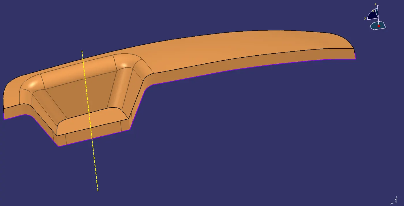
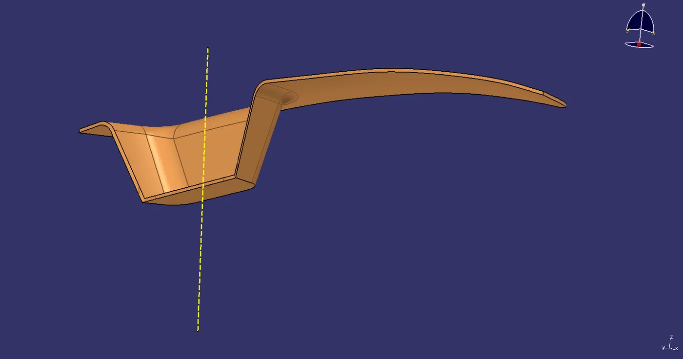
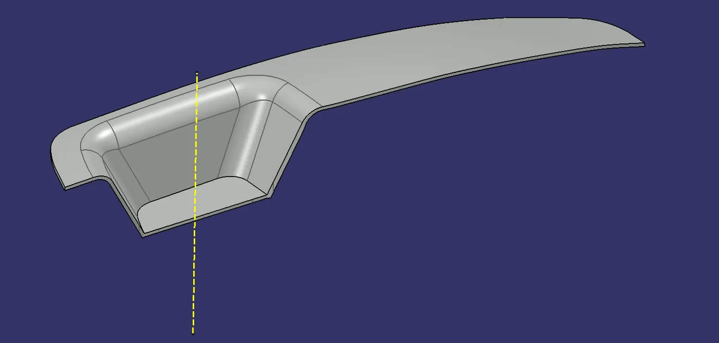
The C-Surface is joined with the A-Surface and then trimmed with the B-Surface. Then it is checked for any open patches using the boundary Command if the command fails, then the surface is closed perfectly.
Then the closed surface is made to a solid by using close Surface command.
Draft analysis:
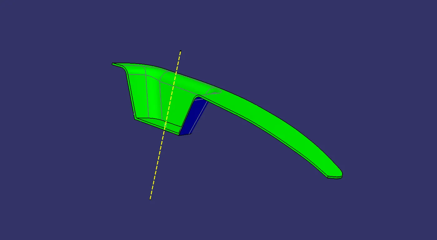
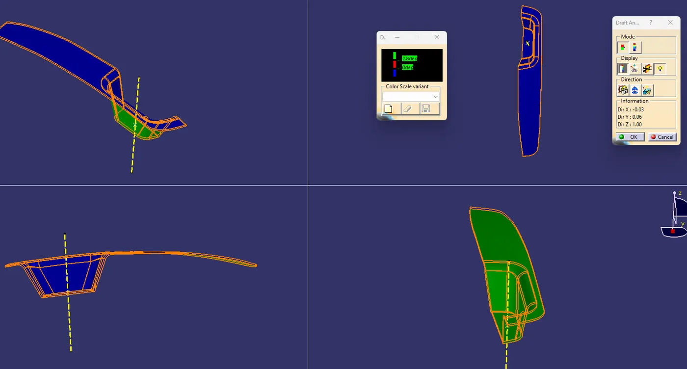
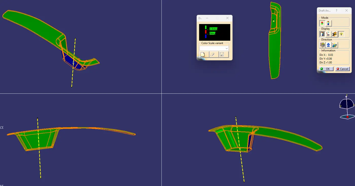
The closed body solid is subjected to draft analysis.
Conclusion:
Hence, the B and C surfaces are created for the given A-Surface of the Switch Bezel part and made a solid body.