Week 9 - Challenge 2 - Switch Bezel Design
Aim: Create the Switch Bezel Plastic component through the given Class-A surface.
Objectives:
- Creation of Tooling Axis by using Class A Surface.
- Creation of Class B surface by using Class A suface with the thickness of 2.5 mm.
- Creation of Class C surface with draft angle.
- Publications: Use the publication option and publish the below
- Tooling Axis
- Class A, B, and C surface
Solution:
Creation of Proper Class A Surface:
The creation of class A Surface is the main task because the CAD file which has been provided was not correct since there was a small gap between two surfaces on the main areas.
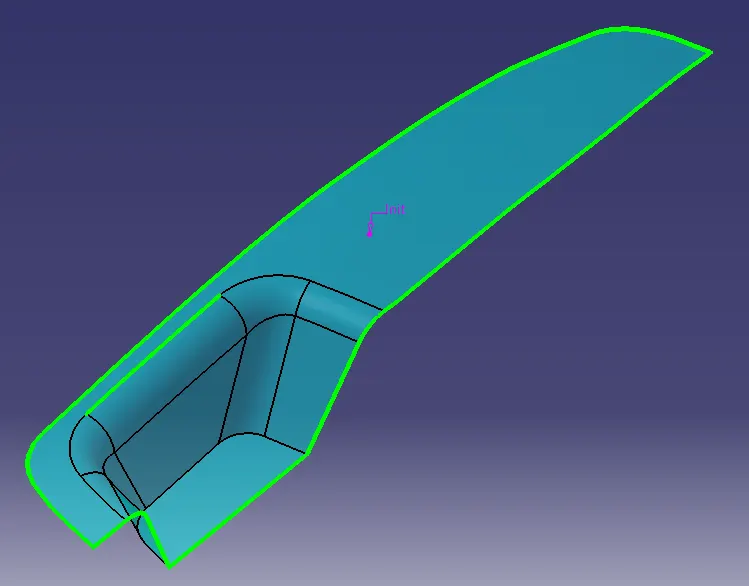
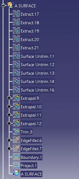
So creating new A surface by extracting the surfaces main wall sufaces and upper and base surface from the given Class A surface.
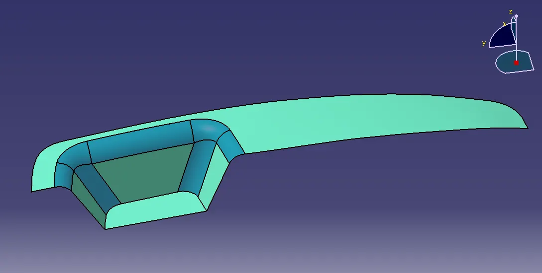
Untrimming and extrapolating the sufaces.
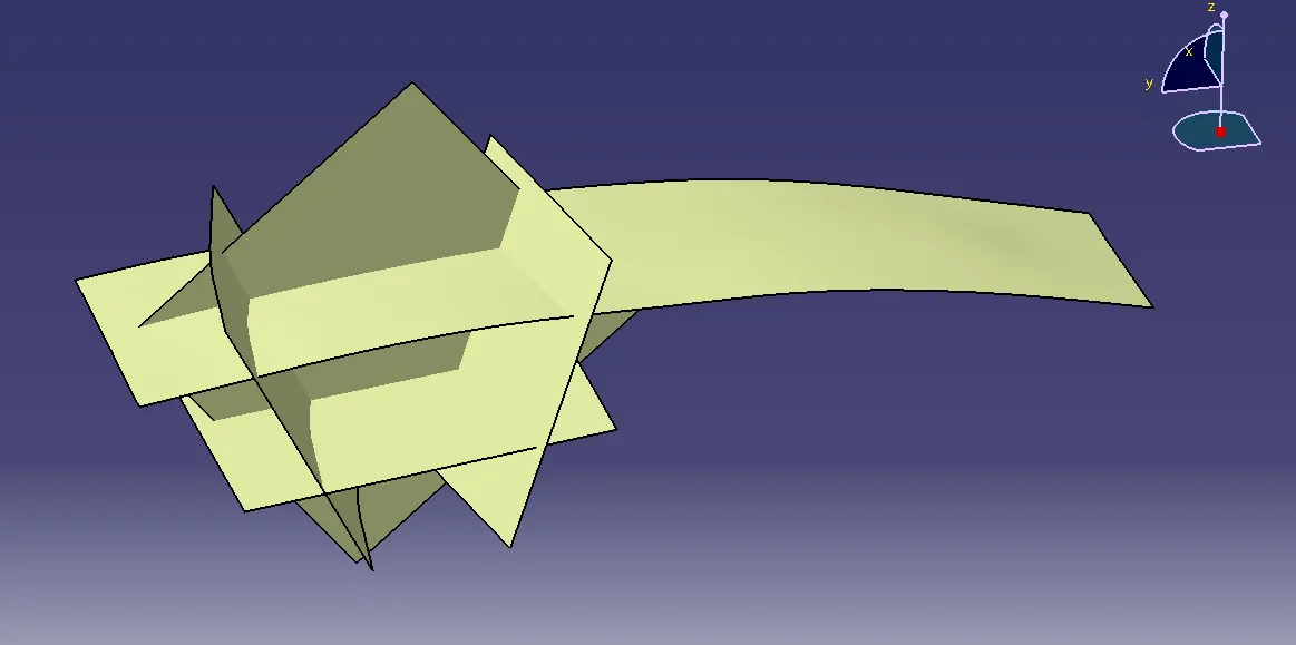
Trimming them and making new Class A Surface from the provided one.
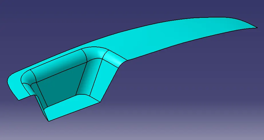
Geometrical Set for New Class A Surface:
Creation of Tooling Axis:
Creation of Tooling Axis by Extracting the main wall surfaces from the new Class A surface.
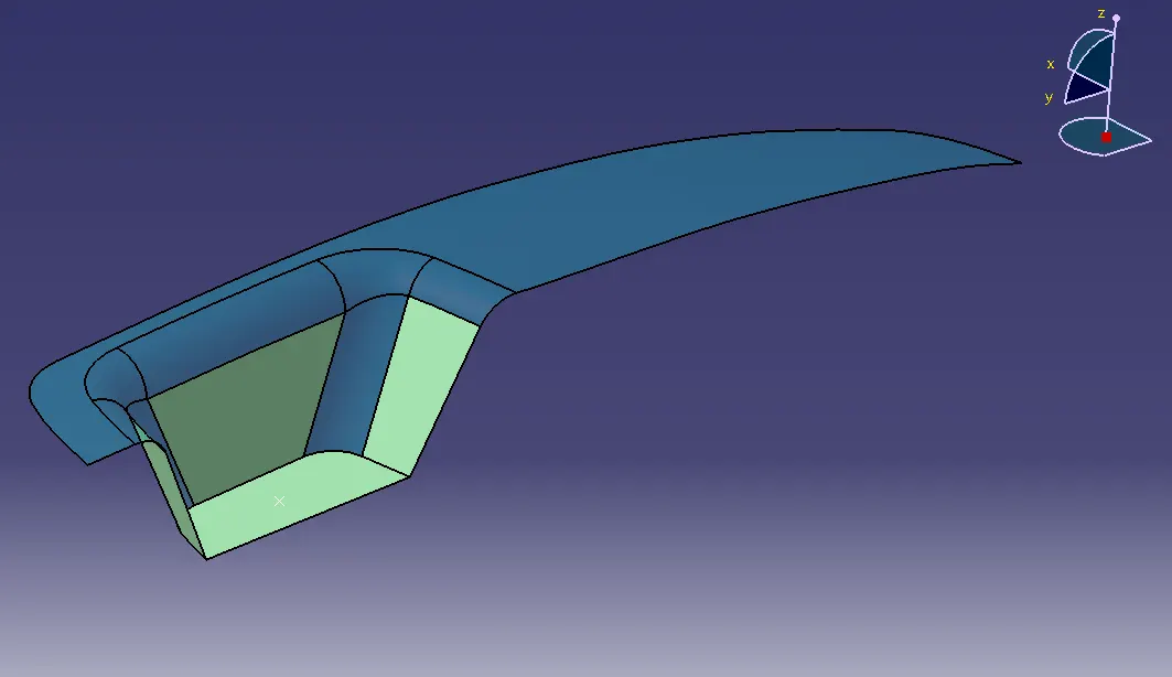
Creating the intersection on the extracted surface by using the Y-Z plane on Axis System on the point created on the surface.
Creating lines on an intersected lines and creating lines bisecting both the lines by using Bisecting Line command.
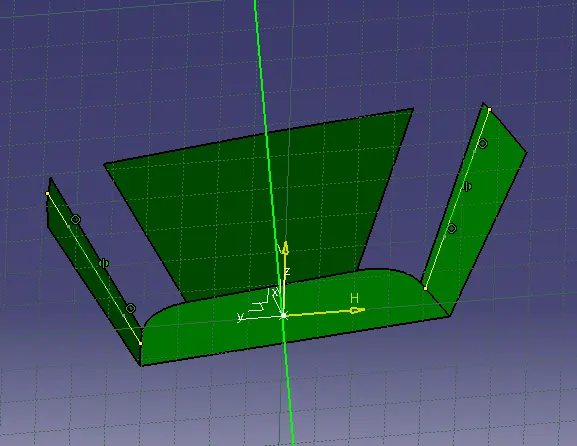
This is the first line will be used to create the Tooling Axis,
To Create the second line, creating an intersecting line on the third wall of an extracted surface by using X-Z plane of an Axis System.
Creating the line at an angle of 6° along with the third wall.
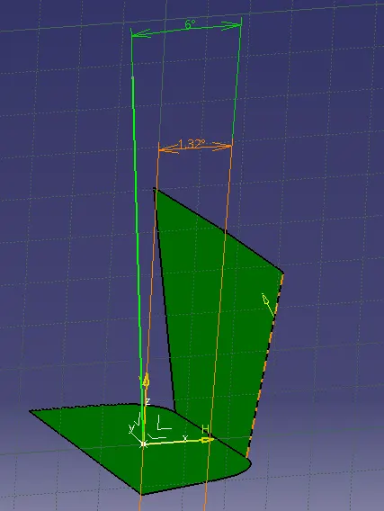
This line is the Second line to create Tooling Axis. This line can be used to make the back wall with an appropriate draft angle.
Using Bisection Line to create Tooling Axis through two lines.
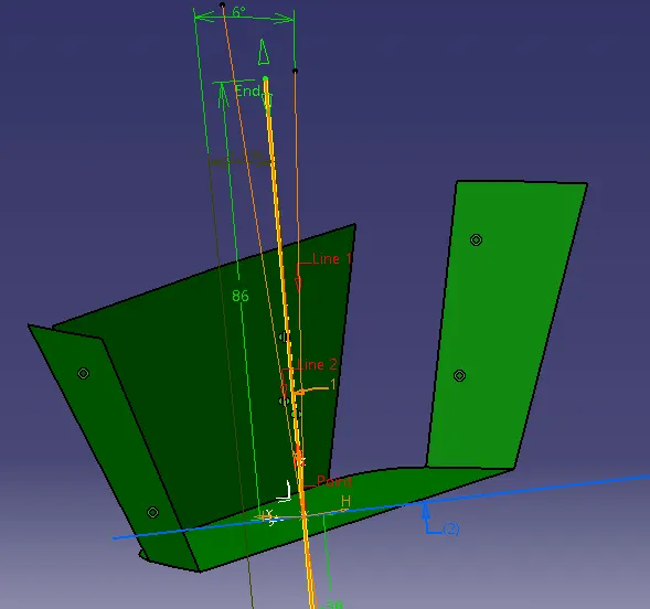
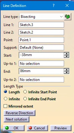
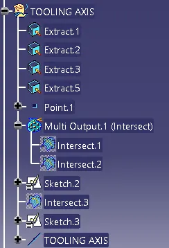
This line is the Tooling Axis.
The line is making an angle of 3.74° from the back wall. To maintain this angle we have given an angle of 6°.
By using this Tooling Axis we can manufacture all the three walls.
Creation of Class B Surface:
Extracting the lower surfaces from the New Class A Surface.
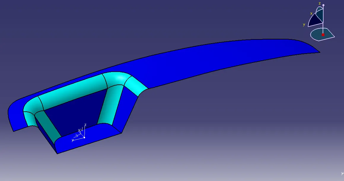
Untrimming and Extrapolating all the surfaces and offsetting them by 2.5mm.
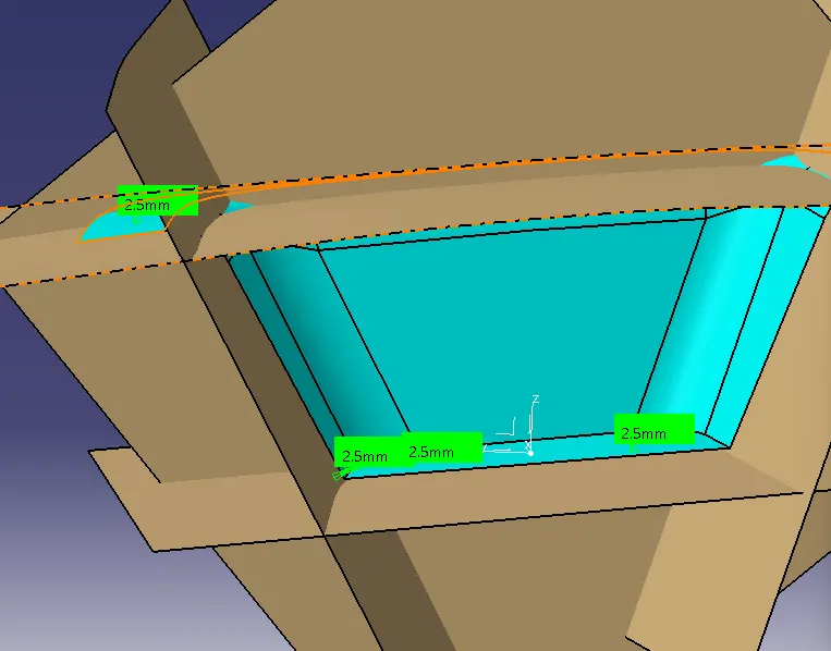
Trimming all the surfaces such as to create the Class B Surface.
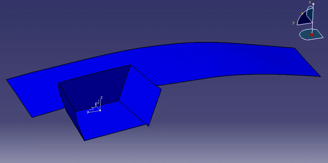
To create the fillet at edges of the surfaces we need fillet radius. To determine that we need to extract the fillet surface of the class A surface and untrim it to find the radius of the fillet.
Creating the Class B Surface by applying fillet on an edge of surface.
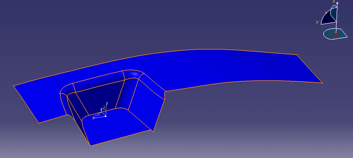
Creation of Class C Surface:
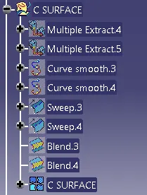
Creation of Class C surface starts form extracting edge of the New Class A Surface.
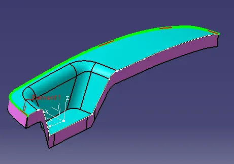
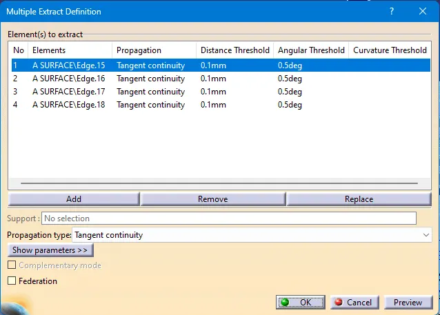
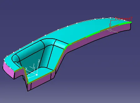
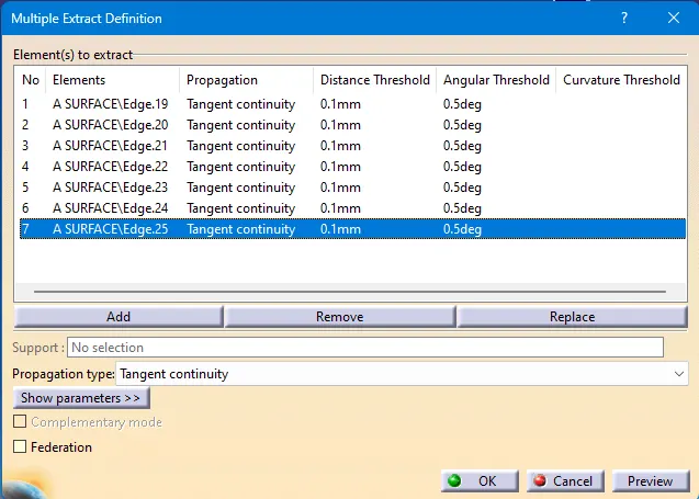
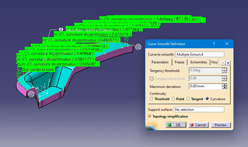
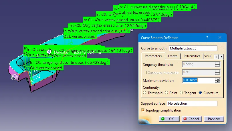
Creating smooth curve of both extracted curves to avoid complexity.
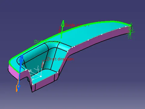
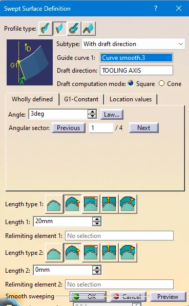
Creating surfaces of both lines by using Sweep command with draft angle of 3°.
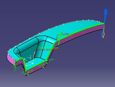
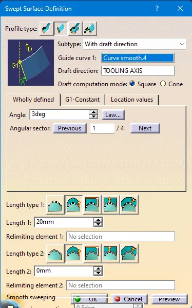
Joining the corners of both the surfaces by using Blend Command.
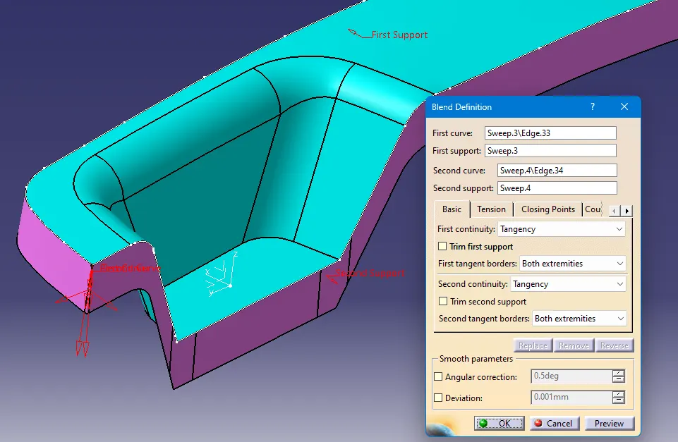
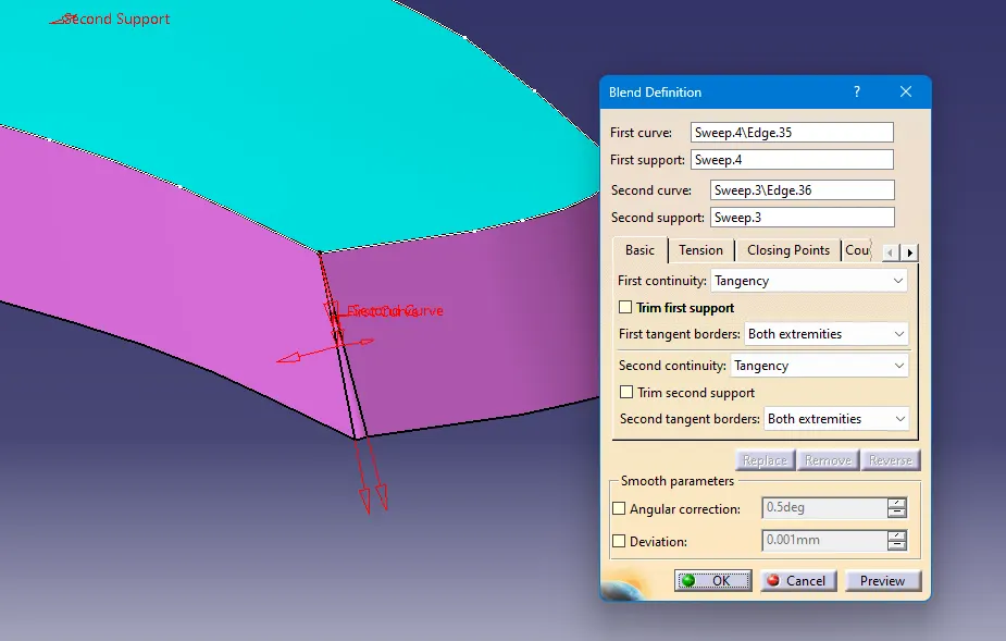
Joining all the surfaces to create Class C Surface.
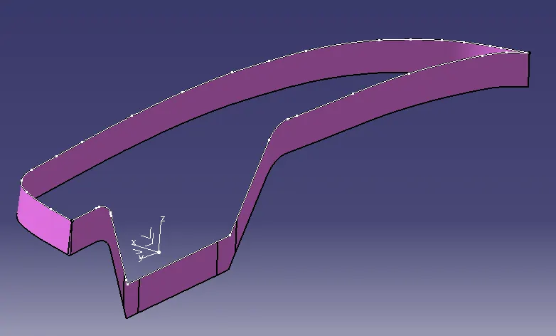
Creation of Final Closed Surface:
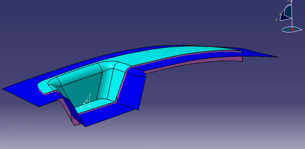
Creating Final Closed surface by trimming Class A, Class B, Class C surfaces.
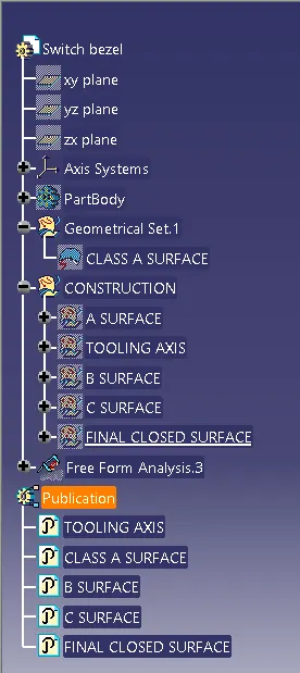
Publishig Tooling axis, all the surfaces and Final closed surface.
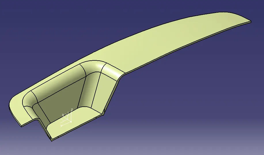
Creating Solid Part form the surface by using Close Surface command in Part Workbench.
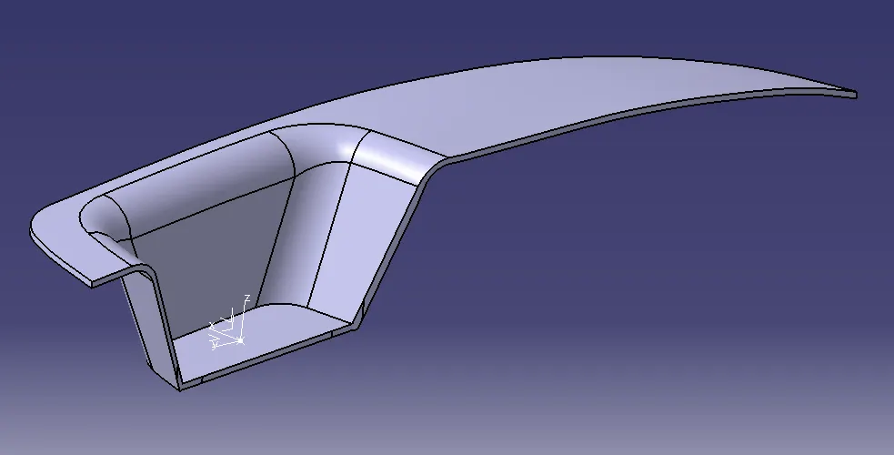
Draft Analysis:
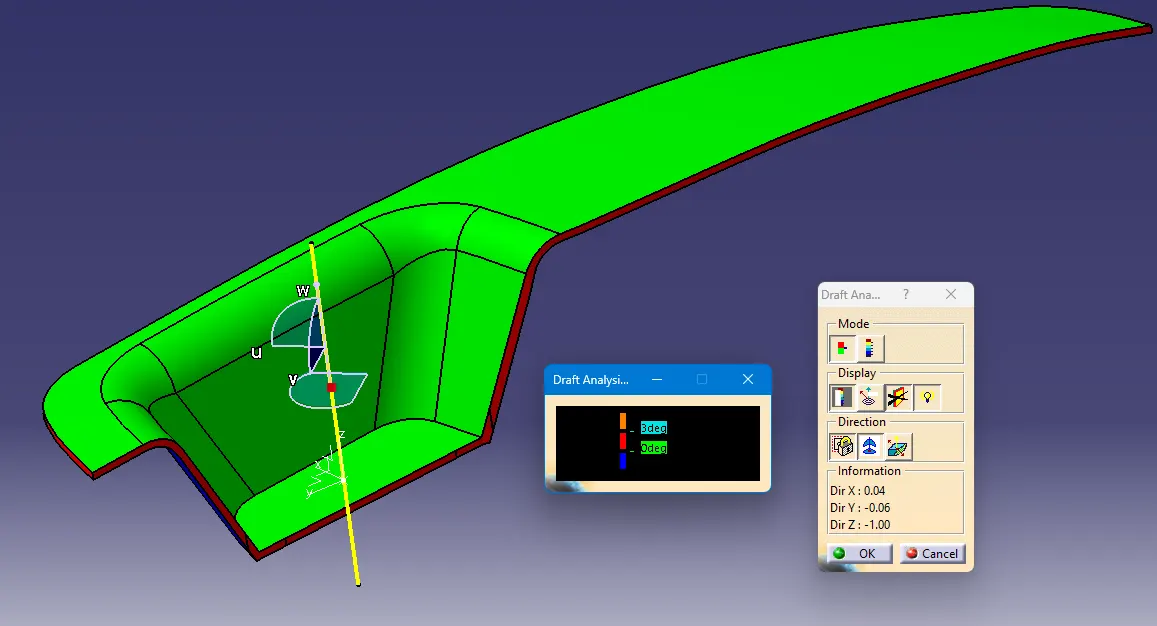
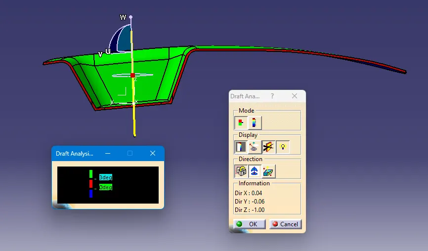
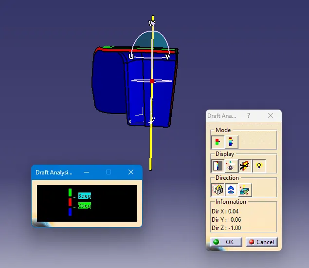
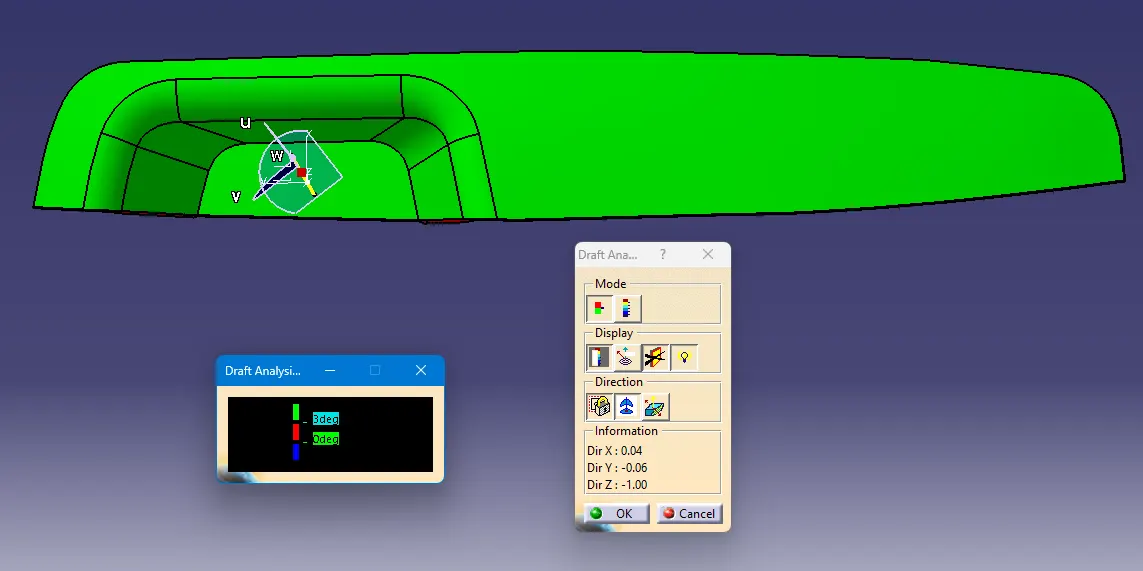
Draft Analysis shows that the tooling axis is correct to make manufacturing of the plastic part of the prescibed thickness and draft angle.