Week 9 - Challenge 2 - Switch Bezel Design
AIM :-
To Create the Switch Bezel Plastic component through the given Class-A surface. To begin with, the tooling axis for the given Class-A Surface should be created meeting the requirements of the draft angle and at the end perform the Draft analysis on the model.
Takiing the Thickness of the component to be 2.5 mm
Abstract & checking the class A surface :-
- From this project i received input as Class A Surface.
- I design a Switch Bezel using Catia v5. I Check the direction to eject the tool based on the component design. Later I checked boundry of overall part, whether all faces that intersected will clear the direction based on the tooling axis.
- I started working on the Draft Analysis tool to check if our tooling direction clears the path for easy removal of material from the tool.
- After that, I go class B creation using Advance tools from the surface followed by class C creation using the sweep command. after design A B C class surface, Thet all trimm to each other .
- By using the part workbench in part body converting close surface into solid inside the part workbench.
1] Checking the Class A surface :-
I have chcked the class A surface with the boundry command. Where all the boundry shown smooth there. But there is an small green line shown At the fillet radius corner, so i merged the surfaces with the join command with 0.003 mm diamension. So Class A surface is ok for the forward B & C surfaces.
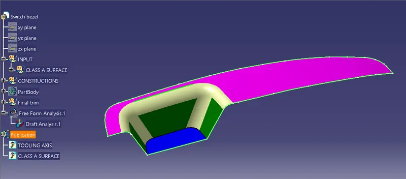
After the merged .
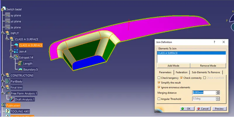
1] Creation the Tooling axis :-
Firstly i created the multiple extract to the element base, After extract to it hide the class a surface. Then ppoint has created on the extracted surface, with the axis system. then select a boundry of the overall xlass A surface. After that intesecting along the YZ plane. Then Created the axis through the referace point along the Z direction. In the intersecting along the YZ plane the bisecting line has created. Same way the intersection has taken along the XZ plane and Created another line . This 2 lines refer take a common bisecting line called the Tolling axis. So the Tooling axis has make in this way.
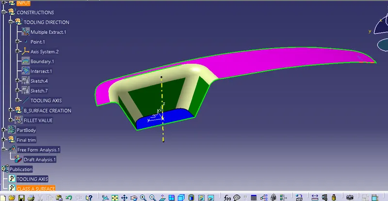
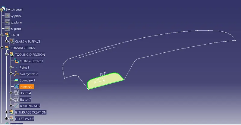
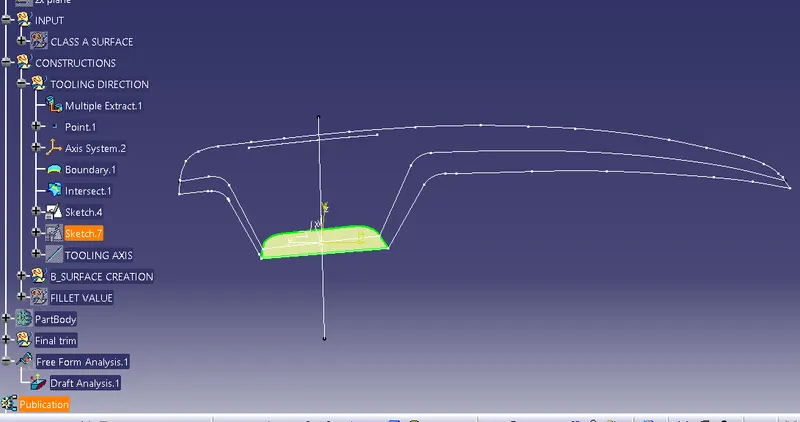
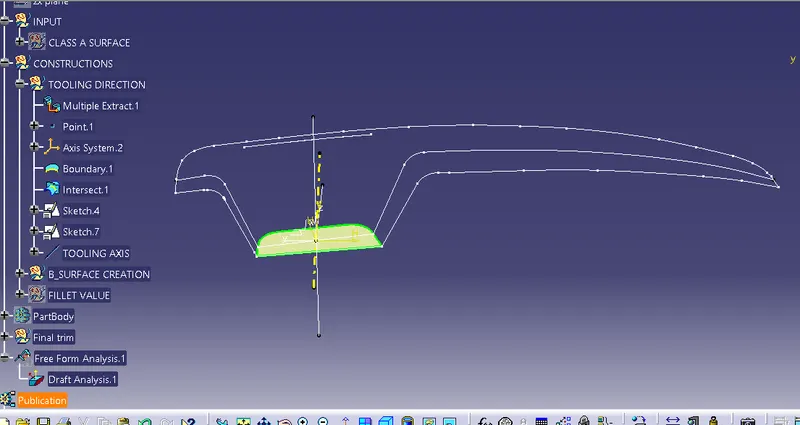
2] B_Surface creation :-
1. Bezel rest surface.
For the creation of B_Surface the sub elements are one by one extruded and offseted it as well to the final trim command, to obtaning a B_ surface proper. Here first the top surface odf a Class a , that means the Bzel rest surface if extruded. then make a untrim to it & Etrapolated. With the 2.5 mm along the downward direction of Class A.
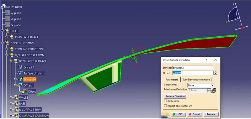
2. Walls
In the second step i have extruded the 3 walls respectively that is lies on the bottom surfaces and along the fillet radius. Then untrimed, Rxtrapolated , offseted & trim as well like a Bezel rest surface creation. And finally join them.
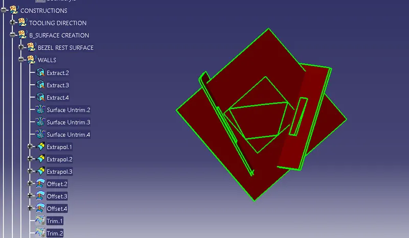
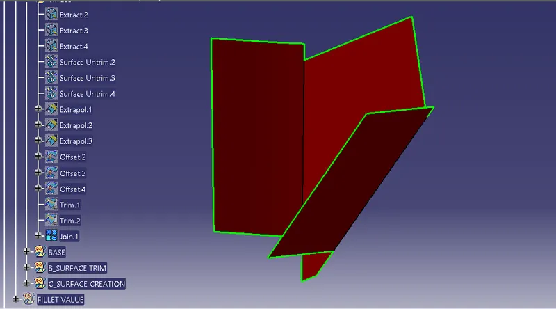
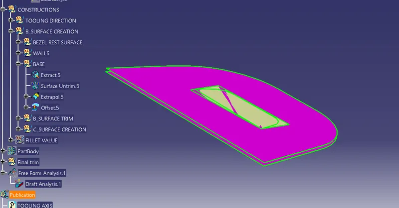
3. Base.
The same procedure is used on the base also.
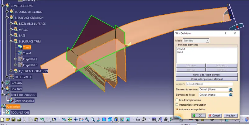
4. B_surfaces trim
The Bezel rest surface & the Walls are trim together. Also after the trimed this again trim with the base surface to got a Final b surface.
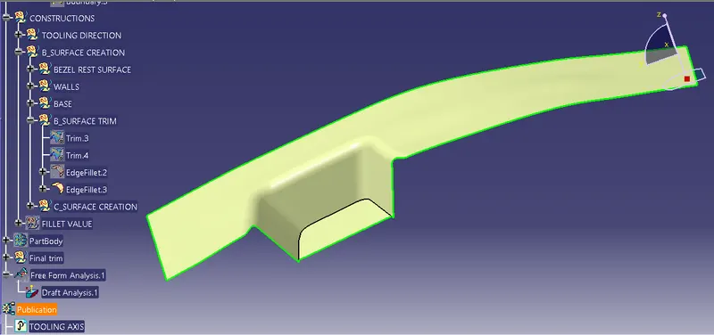
5. Final b_surface & Fillets.
The 2 trims are applied to the bezel rest surfaces and the walls with the base , Then the fillet radius are applied to on it. The fillet 15 mm diamension are applied on a along walls corner & 14 mm are with the Bezel rest surfaces.
3] C_Surface creation
For the c_surface creation, the multiple etract are used to obtained a boundary 1, for the sweep command. And boundary 2 also created with smooth curve to avoiding the patches on the corner or a boundry line.
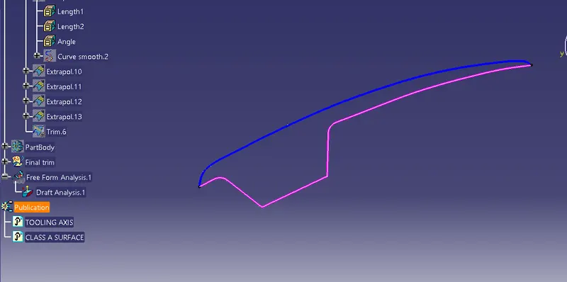
Then the sweep commond is used to the multiple extracted Curve 1 & boundry 2, with 3 degree in the dreaft direction along a Tooling axis.
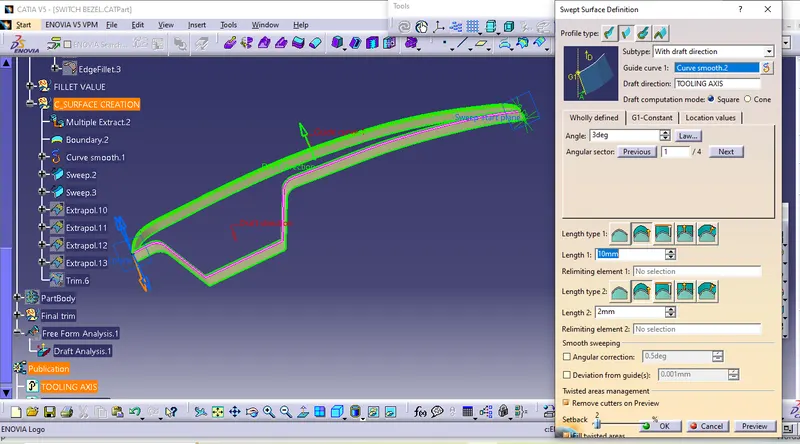
After that etrapolated sweep 1 & 2 at the corner side, because the uncontact and gap is shown that creates an error to the command trim. So extrapoolated it and take a final trim to it to obtained a C-Surface.
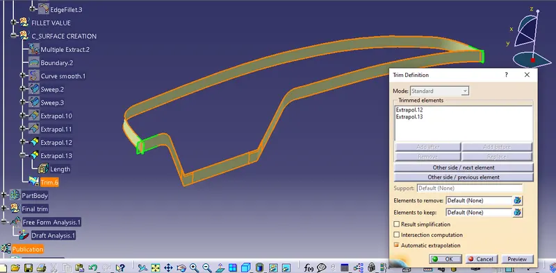
Final C_Surface
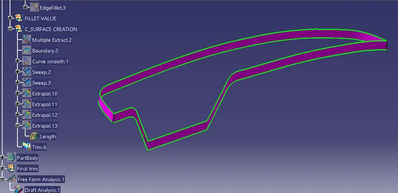
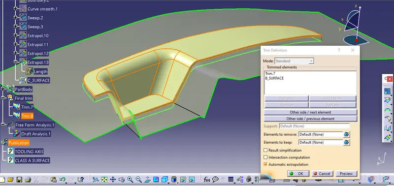
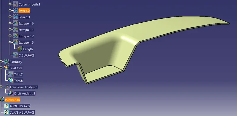
4] Final Trim / Final drated part .
The Class A & Class B surface are trim together, and after the Trimed that is again trim with Class c . To get the Final Closed surface.
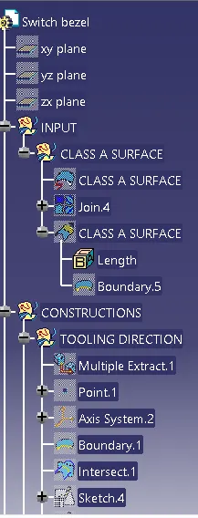
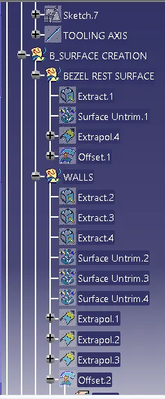
5] WHOLE TREE STRUCTURE
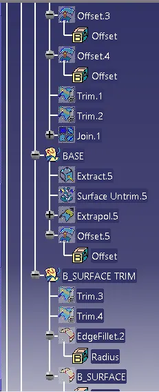
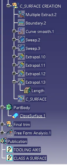
After the final trim i got a closed surface, so catia is capable to make a closed surface in the part workbench in closed surface command. In the part body that is full solid surface.
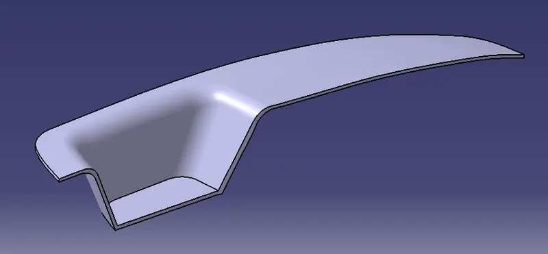
CONCLUSION :-
In this way i have created the closed surface part switch bezel , from the provided Class A surface, with an 2.5 mm diamensional & draft angle to it has 3 degree. Finally part body closed surface has maked in part workbench. All the neccesary A,B,C surfaces & closed body snaps are attached to the report as well. Final Cat part file has browse to the challenge.