Week 9 - Challenge 2 - Switch Bezel Design
AIM:
To create the Switch Bezel Plastic component through the given Class-A surface.
:
- CLASS A SURFACE:
Class A is the surface created by concept sketches done by free hand sketches. The finished sketch is then transferred to a computer, and the 2D surface is created using software such as Alias. This computerized design is known as a Class A surface.
- CLASS B SURFACE:
Class B is a reference surface created by the design engineer and is a copy of the Class A surface at a distance equal to the part thickness.
- CLASS C SURFACE:
Class C is again a reference surface created by the design engineer to connect Class A and Class B surfaces, also known as the side walls of the surface.
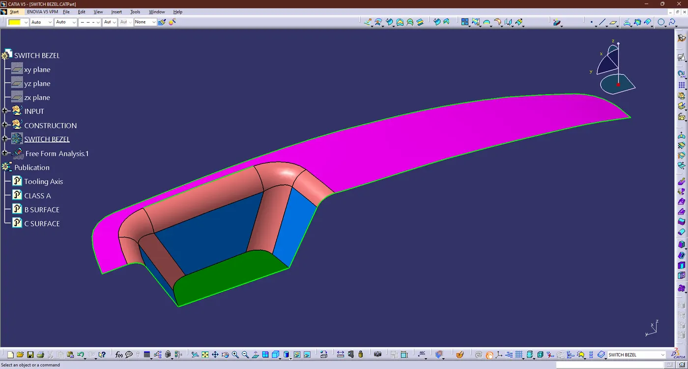
- GIVEN CLASS A SURFACE:
-
The technique used to create the model is to first create a type B surface at a distance equal to the thickness (here 2.5 mm) and then a vertical surface of CLASS C.Then cut the three surfaces to get the desired part.
- Steps for creating the CLASS B & C SURFACES:
- TOOLING AXIS:
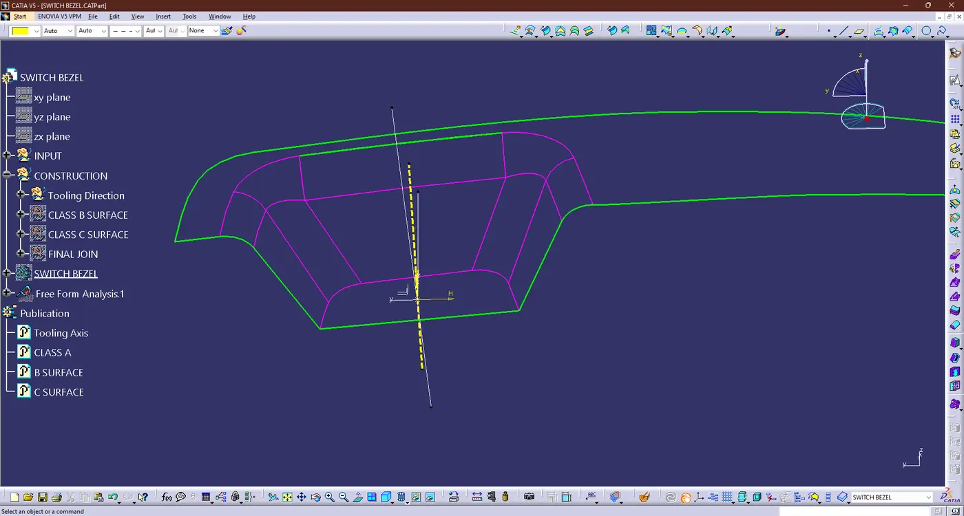
- First we need tooling direction so need to create the tooling axis
- The model is observed from 3 planes and the xy plane is chosen for the details. So the pocket base were chosen and a point has been created
- Let the point taken has the refernece and create a position sketch and then create the two line in the opposite direction
- Then create the another line by using the bisecting line option
- An then create another position sketch other two side of the pocket same as well what should do in the previous sketch
- Now create the another line by using bisecting line option and given name has "TOOLING AXIS"
- DRAFT ANALYSIS:
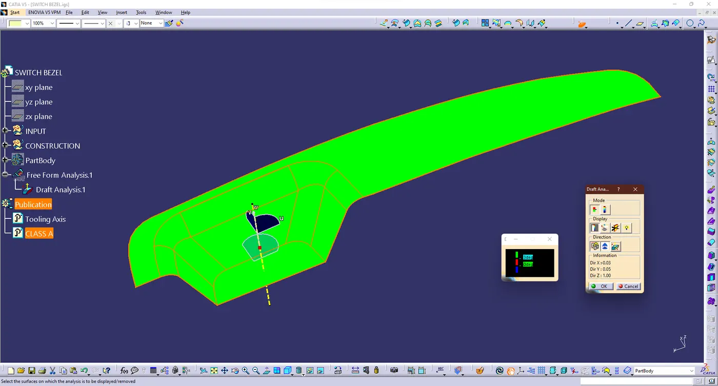
- Now perform a draft analysis using the draft analysis tool included in the tools.
- Then, after opening the draft analysis toolbox, find the compass and align it with the axis of the tool, click the lock icon after alignment, and click add to the surface.
- Checking the surface it should lies on 0.5 to 3 deg and in our case it should lies on the 3 deg
- CLASS B SURFACE:
- A geometry set withh name bezel switch was created, then the entire CLASS A surface was extracted separately.
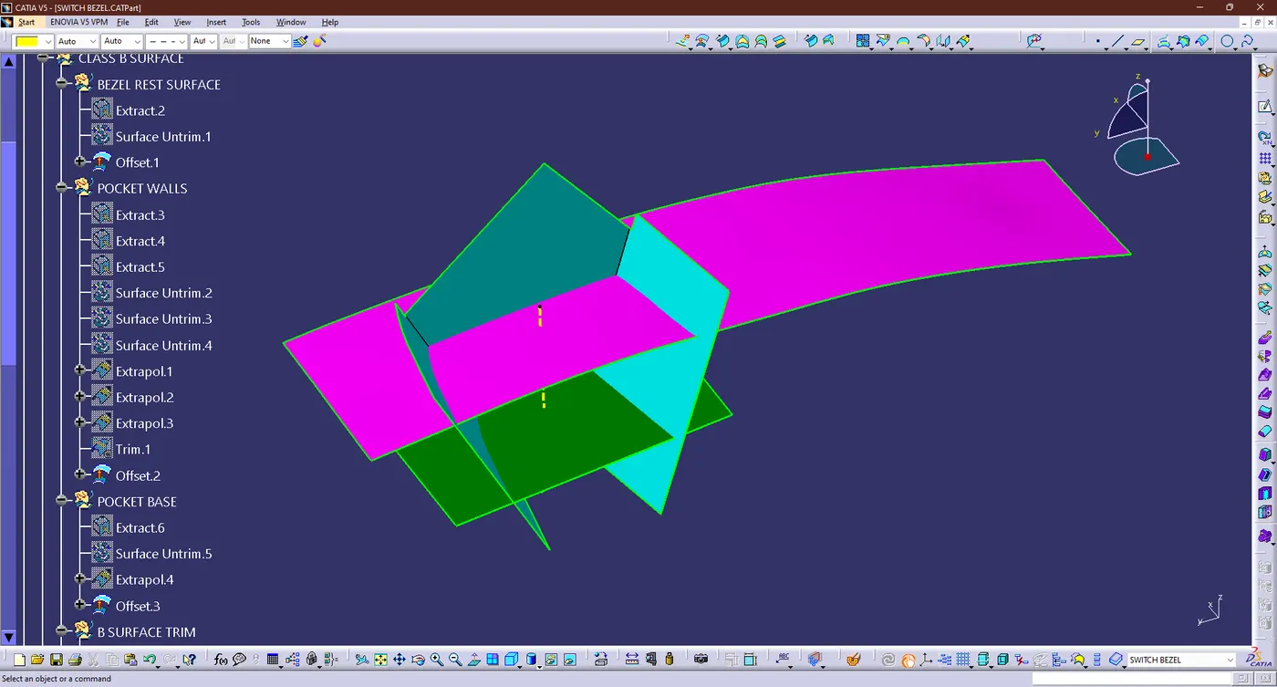
- First thing we need do the Bezel rest surface were extracted and do offset through 2.5mm
- Then do same thing for the pocket wall like wise bezel rest surface and Again do same thing for the pocket base
- Now we got the untrimed Bezel switch like wise mention below
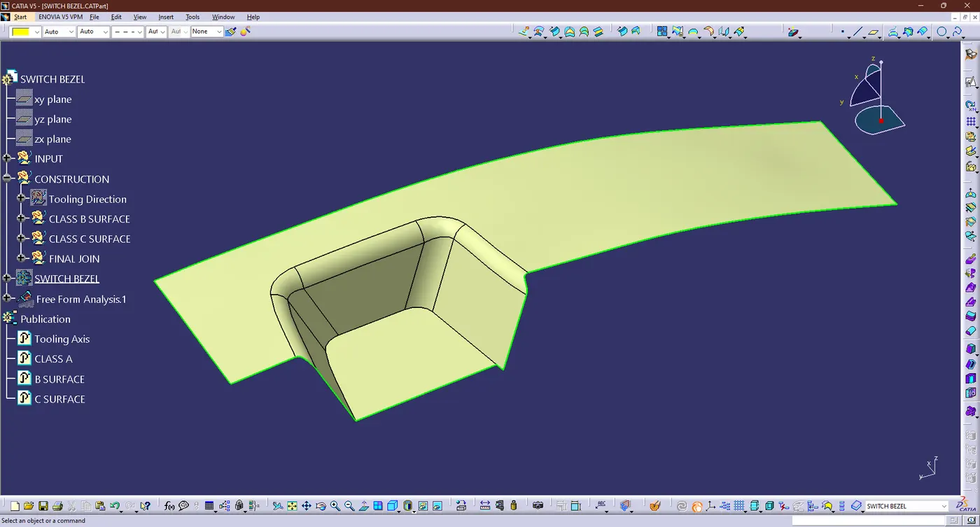
- Now trim the all surface and given fillet as per the CLASS A surface but some different have it offset through 2.5mm from Class A suface so given the accurate values for the each edge fillet i.e 14 - 2.5 = 11.5
- Apply the fillet value then we got the part like this
- CLASS C SURFACE:
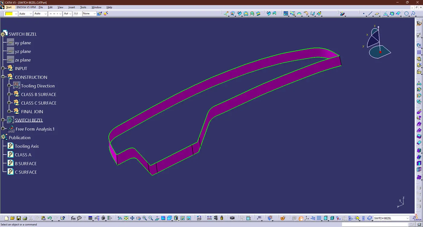
- The Boundary were created for the CLASS C SURFACE from the CLASS A SURFACE
- Now using the sweep command and given reference as main tooling axis, then givne direction of the tooling were considered to create clsss C surface
- Then we got the CLASS C SURFACE like this condition:
- FINAL JOIN:
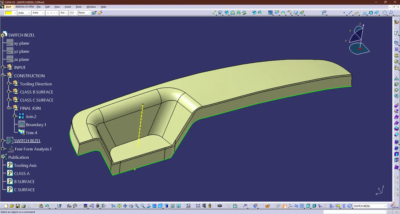
- Now Join the all three surface like CLASS A & C Surface and we got like this
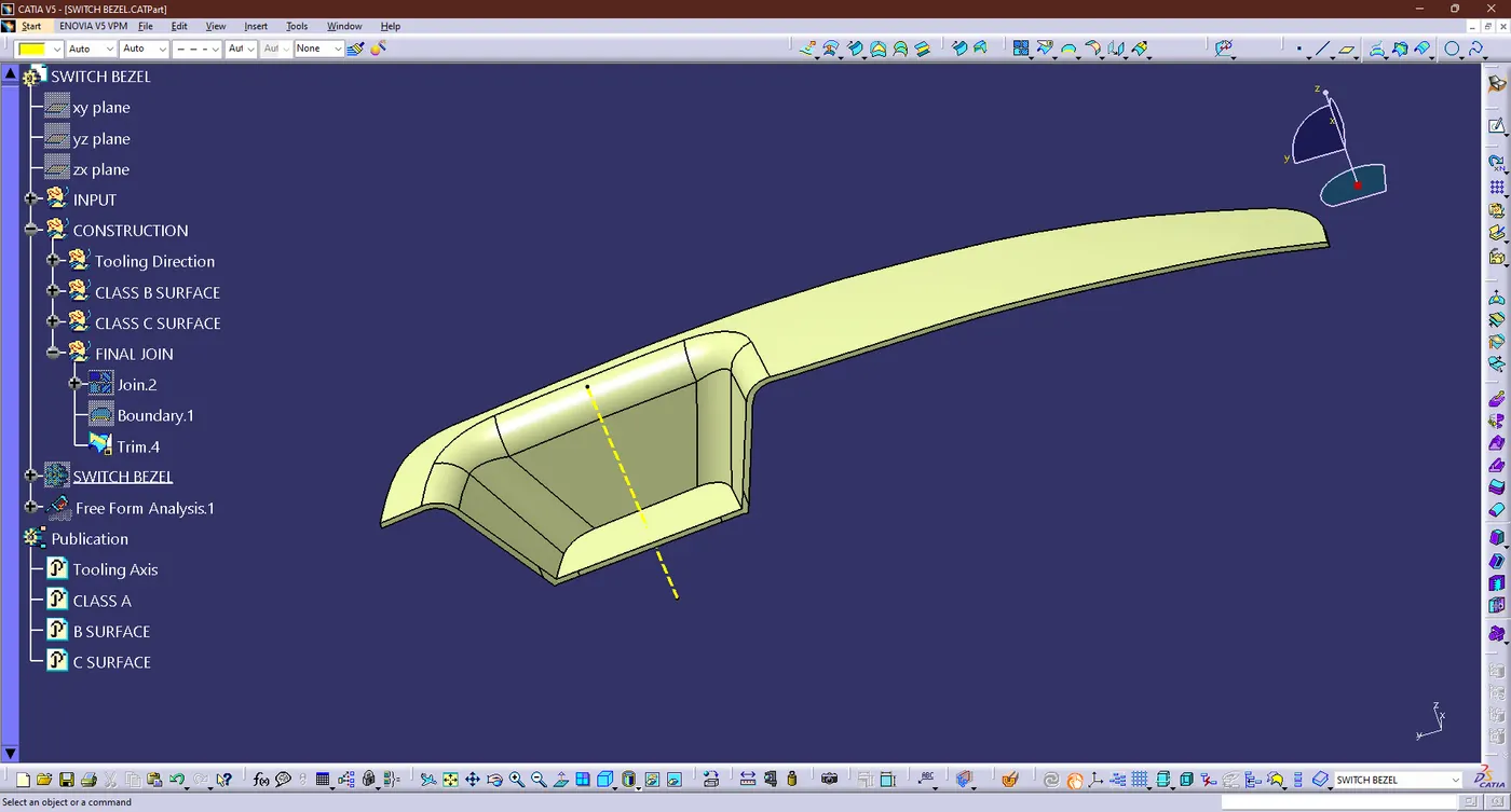
- Then trim with CLASS B SURFACE and we got final output like this
- DRAFT ANALYSIS:
- In Plastic Design, the draft analysis or angle that is considered in the OEMs is 3 degree.
- Same thing were do follow for the draft analysis on earlier and output mention below
- Then we got degree has 2.92 deg
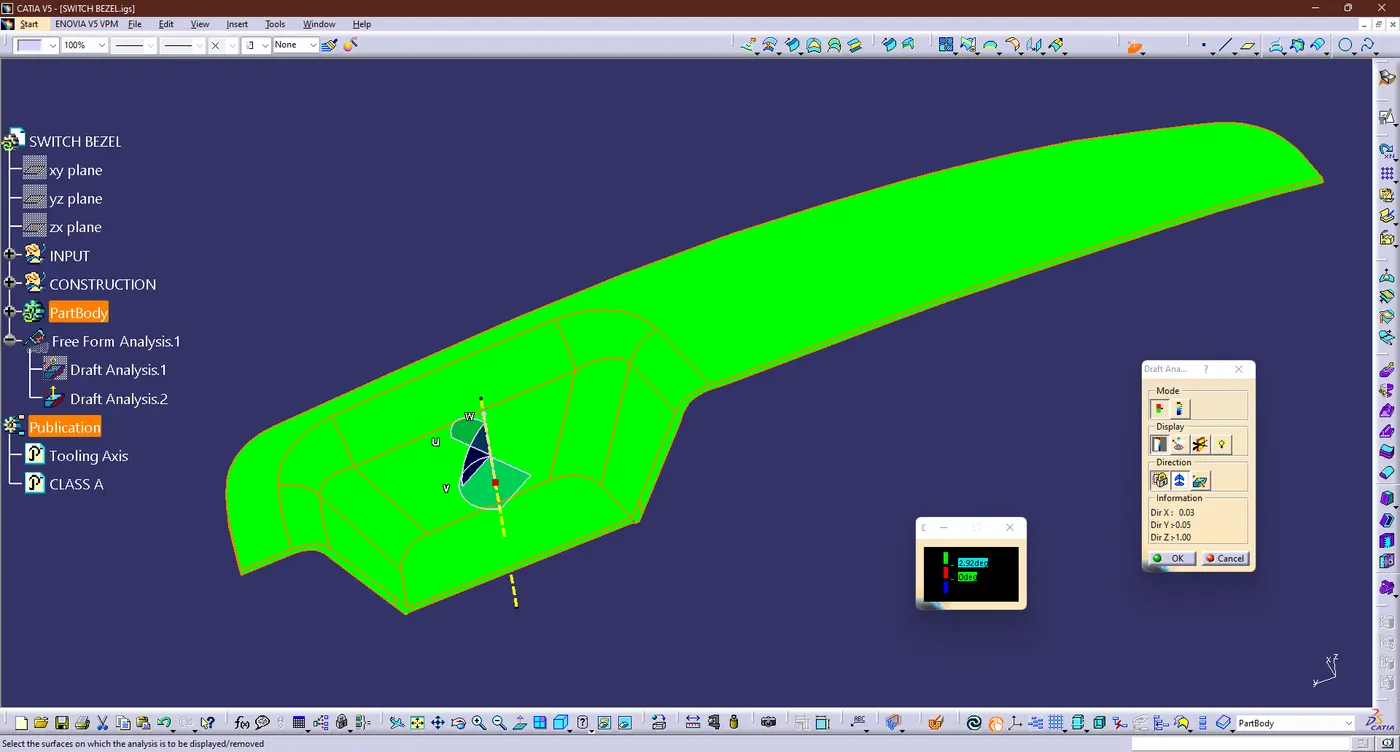
- Draft analysis on the solid part resulted in green, blue regions.
- The green area shows the part that can be machined or manufactured by the casting machine and the angle of inclination is 3 degree
- The blue area indicated that the part may be OK for some OEMs but still needs improvements for other manufactures because the draft angle is greater than 3 degree
- A red color not appearing in this case indicates that the till angle is less than 3 degrees and cannot be manufacuted or if manufacturing will be defective.
- SOLID BODY:
- The hollow is then created as a solid by selecting the Body option and then selecting the Close body surface and hence we got the final output were mention below
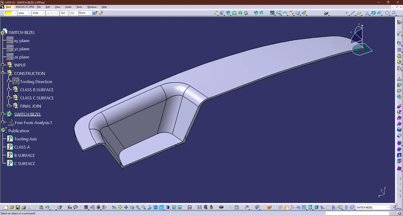
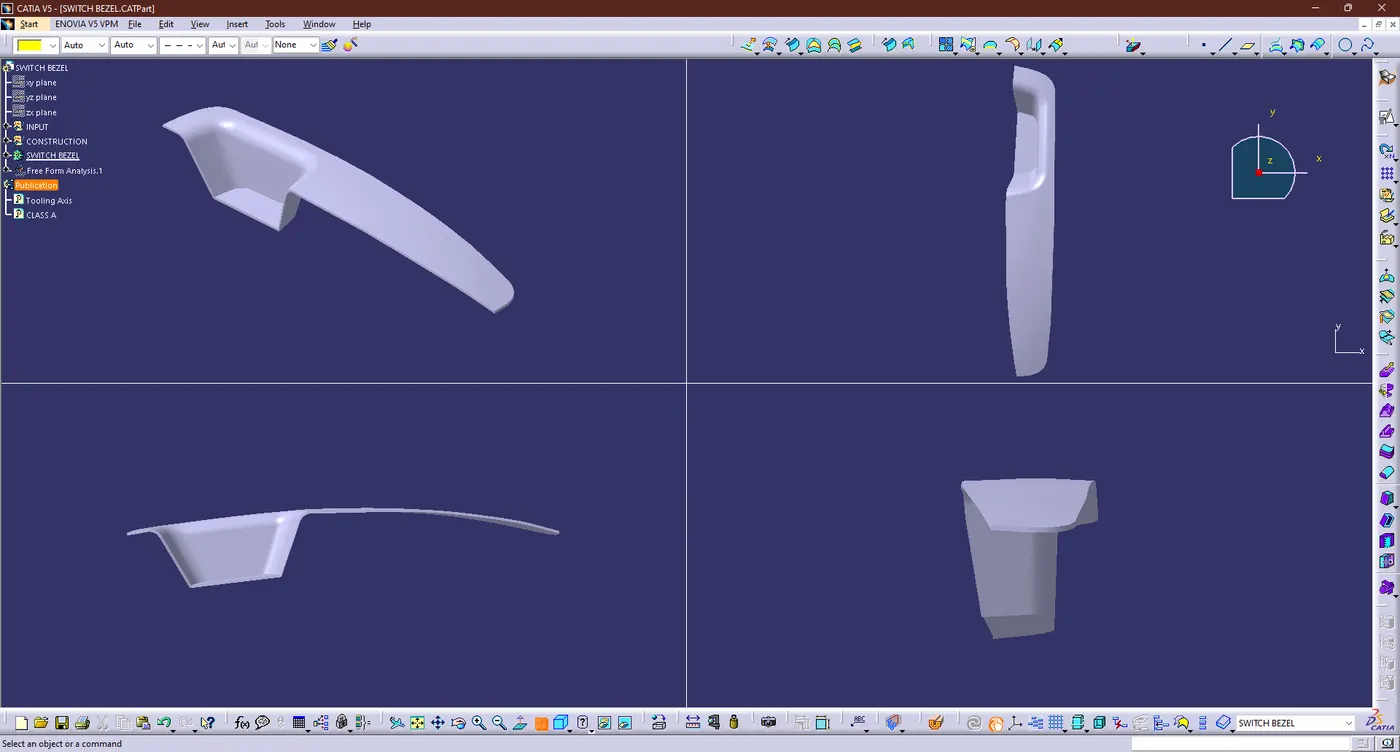
- DIFFERENT ORIENTATION WERE MENTION BELOW:
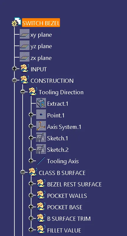
- TREE STRUCTURE:
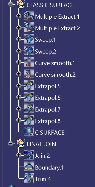
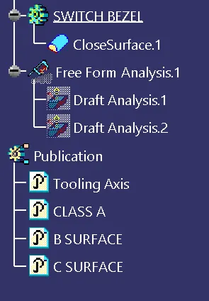
- FILES:
- The output file were mention on browe option in the name of the "week 9 challenge 1 (Bezel Switch).zip" and also output image were uploaded in the same folder.