Week 9 - Challenge 2 - Switch Bezel Design
Challenge 2 - Switch Bezel Design
OBJECTIVE: To create the Switch Bezel Plastic component 3D Solid CATpart in CATIA from the given Class-A surface by using Close Surface feature to make a solid body from the surface by meeting the requirements of the draft angle.
MAIN PROJECT:
Switch Bezel Plastic Design:
Given: Class-A Surface
It is the surface that is created by concept sketches made by free hand sketchers. The finalised sketch is then fed to the computer and a 3D surface is created out of it by the use of a software like Alias.
Tree-Structure of 3D CATPart:
1) High-Level:
2) Detailed:
Tooling Axis:
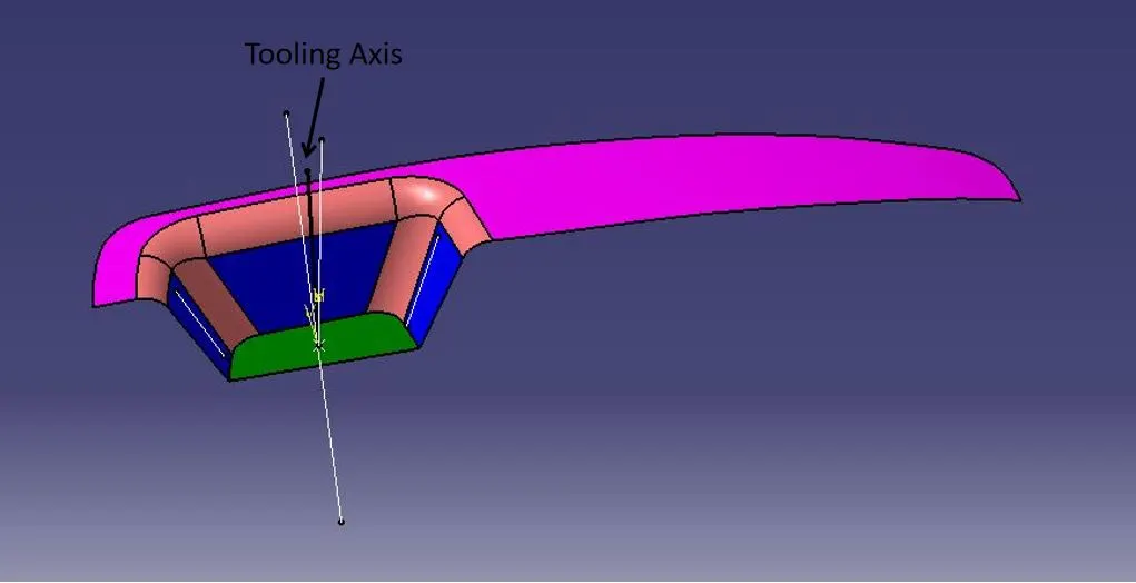
The term "tooling axis" in the context of moulding describes the orientation or direction in which the mould tool or mould cavity is built and designed to open and close. Mold tooling is a critical aspect of the plastic injection molding process, where molten plastic is injected into a mold cavity to produce a finished plastic part.
Tooling Axis Creation:
STEP-1: Extracted the Base Surface from the Class-A Surface and constructed a point in the centre for the tooling axis.
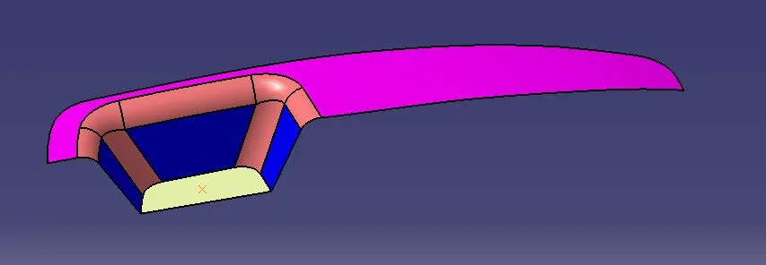
NOTE: Since the Class-A Surface is not symmetrical and to achieve the minimum draft angle of 3 deg, tooling axes are created on both the planes XZ and YZ respectively.
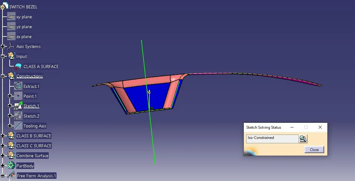
STEP-2: With the help of the Intersect command, the outline sketch of the Class-A Surface along the YZ plane is constructed, and the two non-symmetrical diagonal lines are extended. With the bisecting option in line definition command, the tooling axis line 1 is constructed.
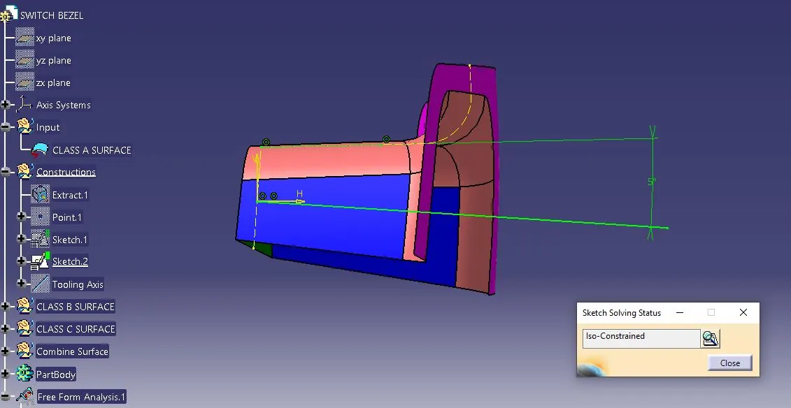
STEP-3: With the help of the Intersect command, the outline sketch of the Class-A Surface along the XZ plane is constructed. To acheive the final 3 deg drafting angle tooling axis, a line (tooling axis line 2) was drawn with a measurement of 5 deg with respect to the line create over the outline sketch.
STEP-4: The final tooling axis was constructed by bisecting both the tolling axis 1 & 2.
Class B Surface:
It is a reference surface that is created by the design engineer and its a copy of the Class-A Surface that is at a distance equal to the thickness of the part.
Class-B Surface Creation:
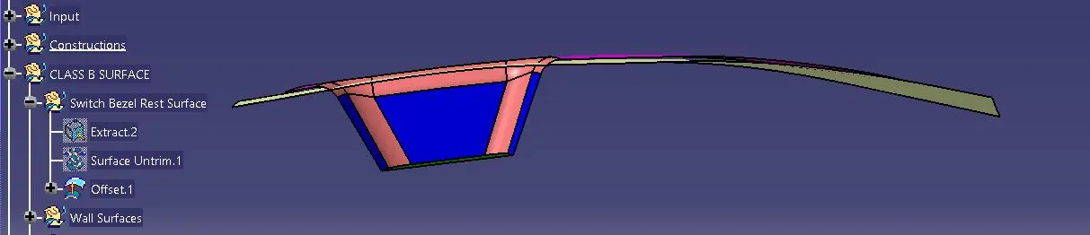
STEP-1: A geometrical set of Switch Bezel Rest Surface was created under the Class B Surface.
STEP-2: Then the Switch Bezel Rest Surface from Class A surface is extracted, untrimmed and finally offsetted 2.5 mm downwards.
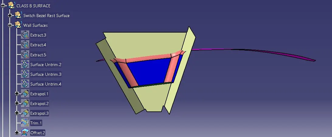
STEP-3: Again the non-filleted region of side wall surface from Class A surface is extracted, untrimmed, extrapolated and and finally trimmed to get the surface looks like before filleted. After that offsetted 2.5 mm outwards.
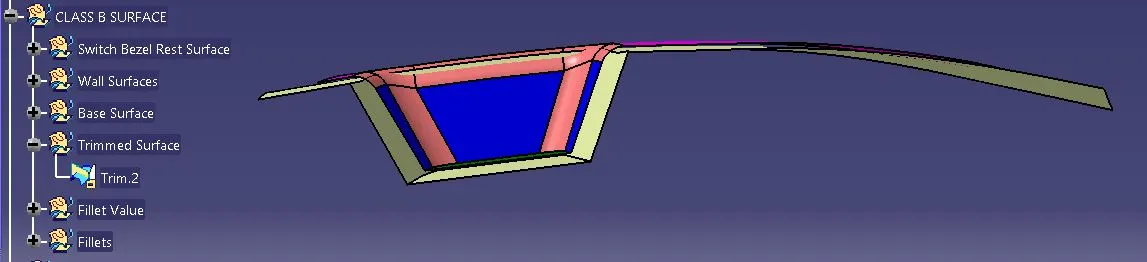
STEP-4: Both the offsetted surfaces are trimmed to form the non-filleted Class-B Surface.
STEP-5: The fillet radius is measured by extracted and untrimmed them.
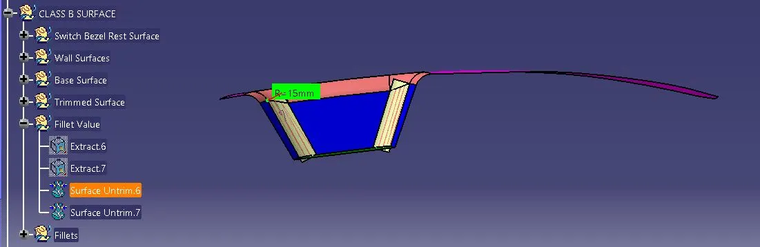
STEP-6: Fillets are provided based on the Class-B Surface by the formula.
Class-B Surface Fillet Radius = Class-A Surface Fillet Radius (+ or -) Thickness of the bracket
+ for offset upwards
- for offset downwards
Class C Surface:
It is a reference surface that is created by the design engineer to connect Class-A and Class-B Surface also known as the side wall of the surface.
Class-C Surface Creation:
STEP-1: The boundary was created by considering the Class-A Surface.
STEP-2: By using Sweep command, contructed the Class-C Surface with the default draft ange of 3 deg for a distance of 15mm. And joining both the Class-A Surface and Class-C Surface by using Join command.
STEP-3: After that, with the help of Trim command got the final shell of closed surface.
Part Body Creation:
STEP-1: Finally, the Switch Bezel Plastic component 3D Solid CATpart is created by the Close Surface command.
Part Draft Anaysis:
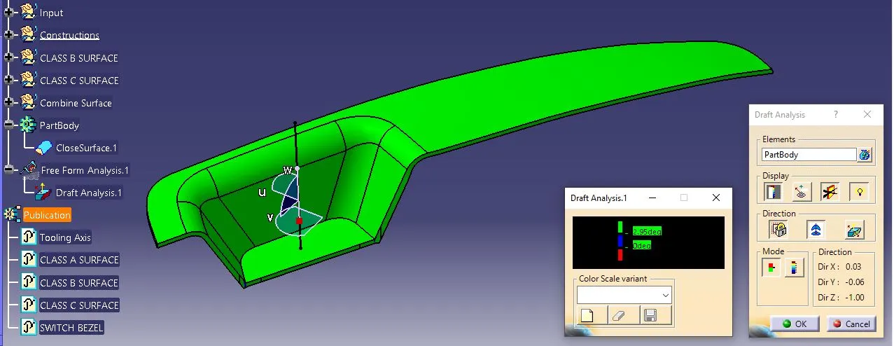
Draft analysis on the solid part resulted in green and blue regions.
1) The green region states that the part is toolable or produceable by the molding machine and the draft angle is 3 deg.
2) Blue color region states that the part can be produceable but still need to be improved as the draft angle is exact or more than 3 degrees.
3) Red color which is not there in this case states that the draft angle is less than 3 degree and cannot be produced in normal quality molding machine eventhough if produced it will result faulty.
Various Views of Base Bracket:
Isometric View:
Front View:
Side View:
Conclusion:
Thus, the Switch Bezel Plastic component 3D Solid CAT Part created in Catia software by Close Surface method and also met the requirements of the draft angle.