Week 9 - Challenge 2 - Switch Bezel Design
Report On Surafce Design of Plastic Component (Switch Bazel)
Draft Analysis :Draft analysis refers to a tool that allows us to determine wheather the designed part can be produced properly or not when Core or Cavity part of plastic mold is removed. In catia if defined draft direction is along the tooling direction and if Colour on the outer surface (Facing towards the draft direction) is green then we can conclude that the part can be produced efficiently .
Here are the steps to use Draft Analysis in CATIA:
- Enter the part in CATIA.
- Go to Material Mode.
- Go for draft analysis.
- Drag axis bar to the tooling direction of part.
- Then check the draft analysis.
Let us take example of Switch Bazel-
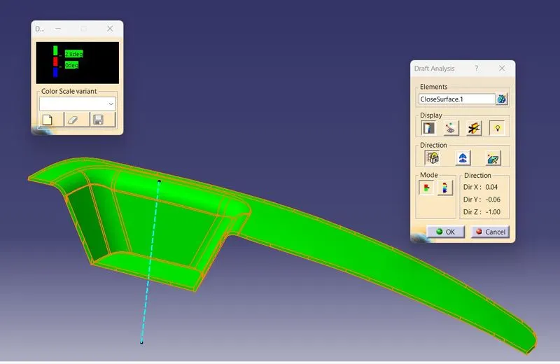
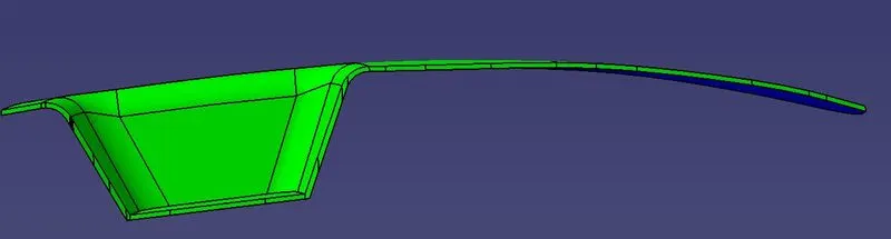
Here, after draft analysis the colour is green along the tooling axis (Blue doted line) which means our switch bezel design is okay and ready to manufacture. Here minimum draft angle is 2.8 Deg.
Tooling Axis : Tooling axis is the axis or direction along which draft analysis is done and the core or cavity moves. It is very important to choose write axis for tooling.
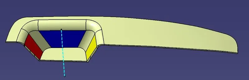
In the above blue doted line is the tooling axis . It is created by the following method:-
1.We have take two lines one on each of Red and Yellow surface such that they lies on same plane.
2. Then we make bisecting line from the two lines.
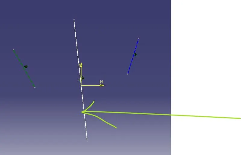
3. Now We take one line on Blue surface and one line through the base surface such that they both lies ob the same plane. And also the angle between them should be greater then 3deg , here we have taken 6deg for better result.
4. Now the final Tooling axis will be obtained by bisecting the lines generated by point-2 and point point-4 which is nothing but the blue dotted line is the tooling axis.
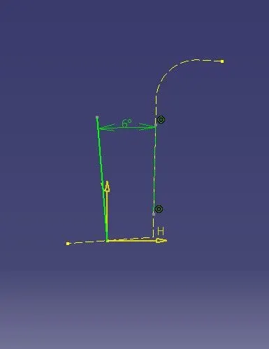
The below blue dotted line is the tooling axis.
Different Views of the Switch Bazels with draft color code:
Isometric View:
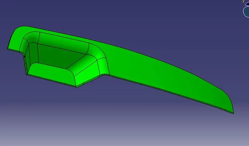
Top View
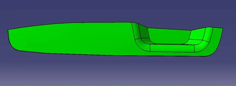
Bottom View
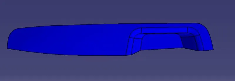
Front View
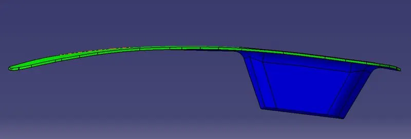
Back View
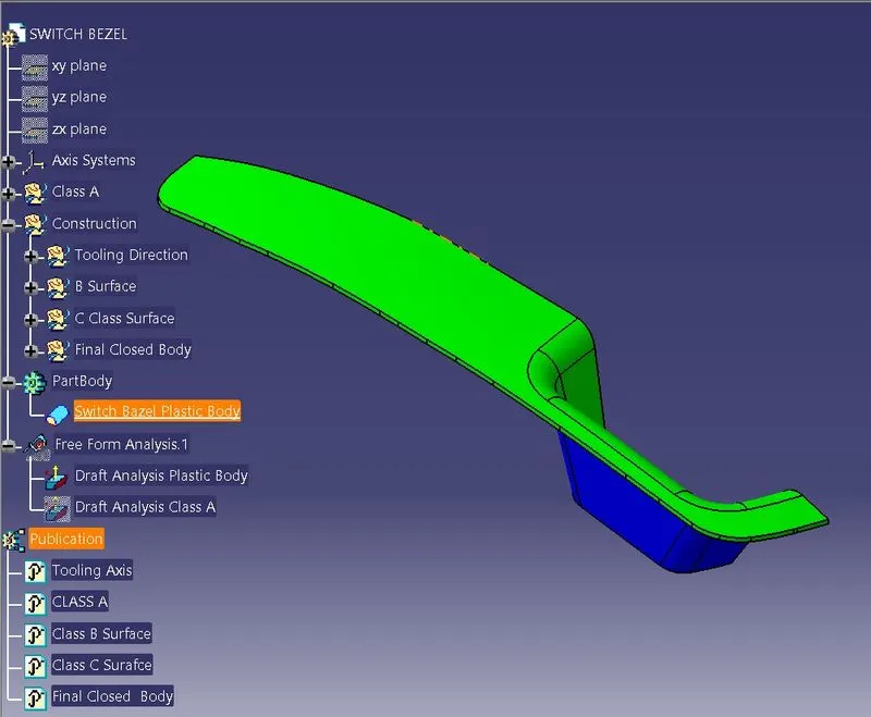
Tree Structure:
Report Prepared By: Vikash Rai