Fender Design - Wheel Arch Challenge
Report on Fender Design - Wheel Arch Calulation.
Parameters for fender wheel arc design : While designing the fender wheel arc, we have to think of abount two parameter.
1. The gap between the outermost surface of the tyre and the inner most surface of the fender .This gap is seen from top/bottom side. This is generally represented by "L".
2. The space between the maximum diameter of the tyre and the the inner edge of the fender or fender wheel arc. This gap is seen from side view. This is represented by "a".
Japan Requirement: The clearance value of "L" and "a" should be more 5mm .
Europe Requirement: The clearance value of "L" should be greater than 10mm and clearance value of "a" should be more than 5mm.
USA Requirement: The clearance value of bothe "L" and "a" should be be more than 5mm.
The value of these two parameters varies from region to region as it mostly depends upon the road condition at the same time it should satisfy pedestrian safety regulations. The value at Japan, Europe and USA is mentioned above.
So, for same model of a car it is very convient for any OEM to follow the europian standard as if it satisfy Europian standard then automatically remaining other two standards are almost satisfied.
So, here Wheel arc calculation will be based on Europian Standerd.
Procedure to Calculate the Value of "L":-
Fig:1
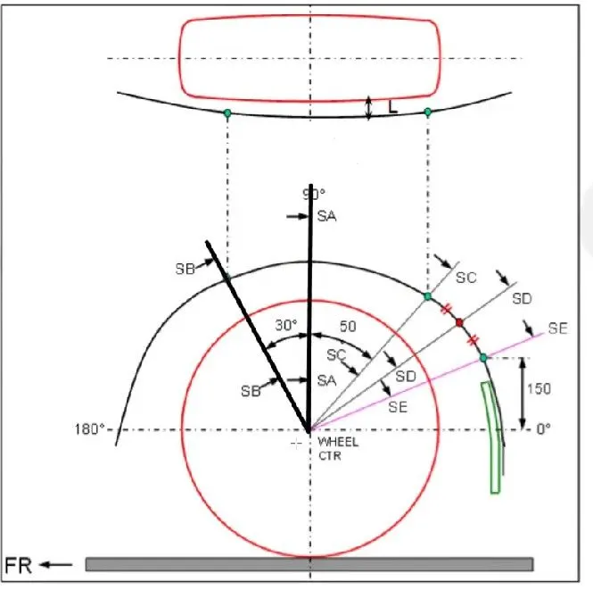
The above image is the procedure of calculating the value of "L" :-
First for all we will take a datum plane exactly upon the outher most suface of the tyre.
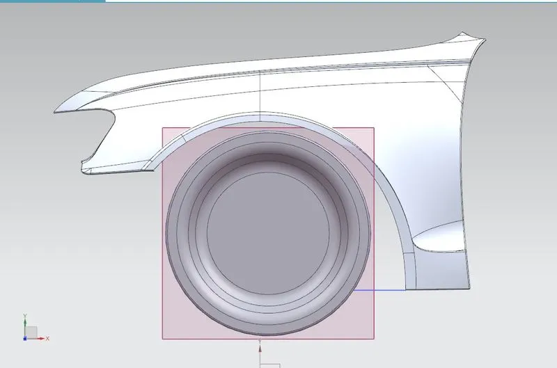
Then we draw lines with fixed value of angles as shown in Fig:1 at five different points as in the figure.
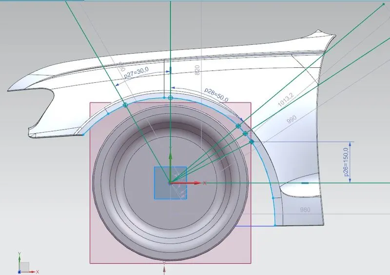
Now we will project the lower-most curve of the wheel arc of the fender on the sketch plane.
Then we will have to find out the five different intersecting points as shown below.
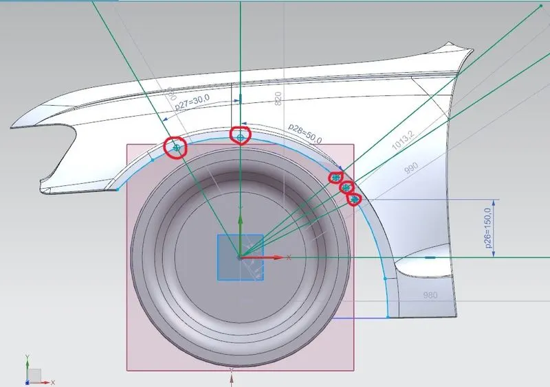
Now we will finish the sketch. Then we project these five points on the fender wheel arc area.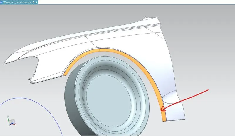
The yellow region is the fender wheel arc area. We will try to project all those points on this surface.
Fig:-2
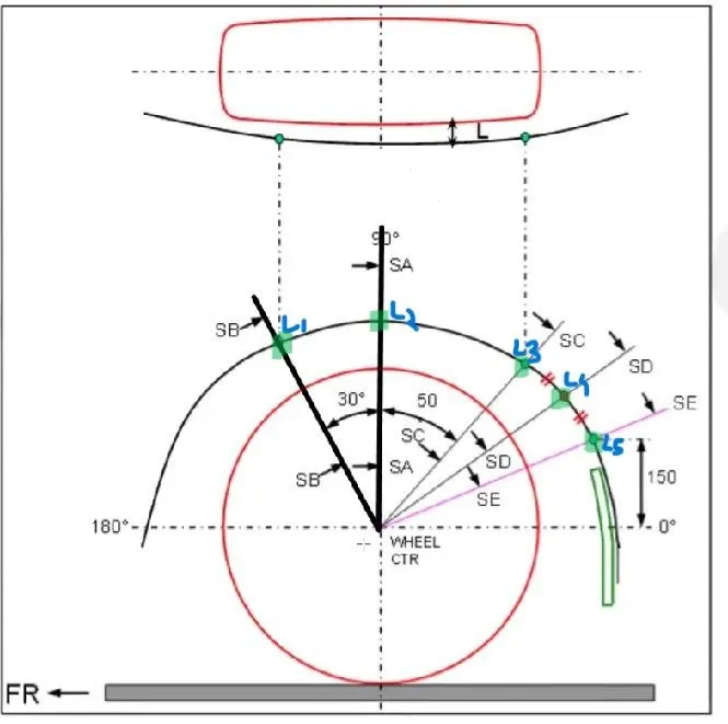
In the above figure, L1,L2,L3,L4 and L5 are value of L at 5 different locations as per figure no. 1.
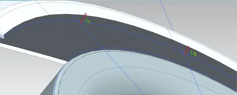
The red line is nothing but the required length "L" . With help of measurement tool we will calculate this value of "L" at the five points as per drawing .
The value of L1 = 10mm.
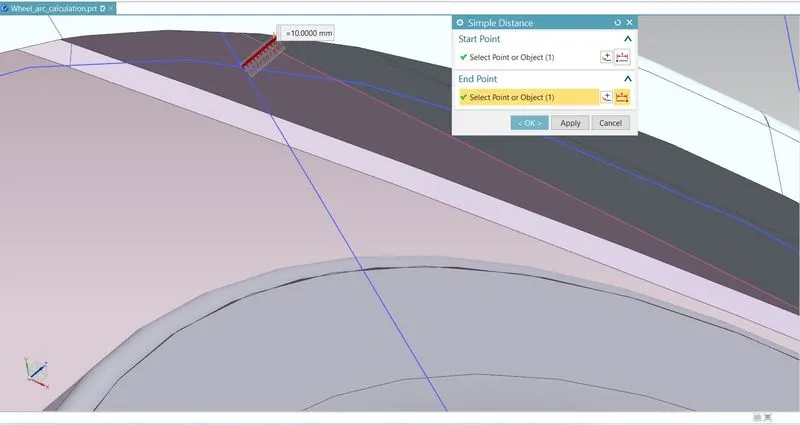
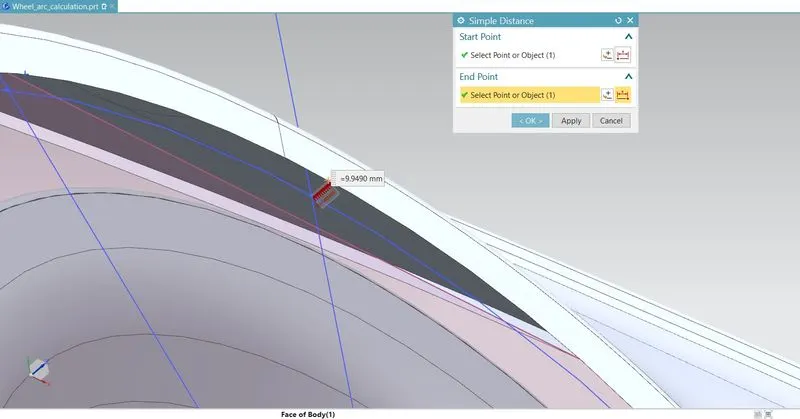
The value of L2= 9.9490 mm
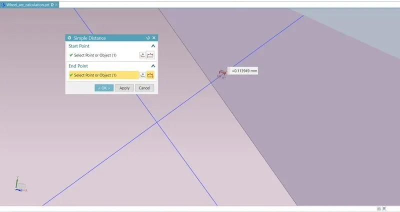
The value of L3= 0.113949 mm
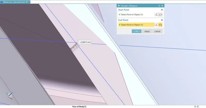
The value of L4= -2.8875mm
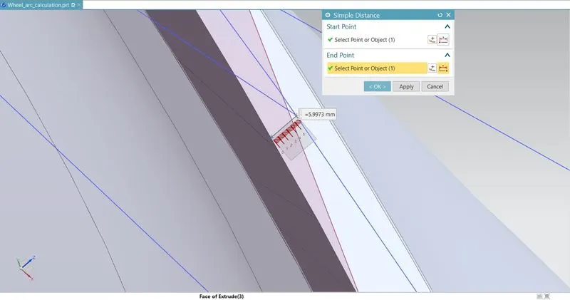
The value of L5= -5.9973 mm
Final image for value of L at 5 desired locations are:-
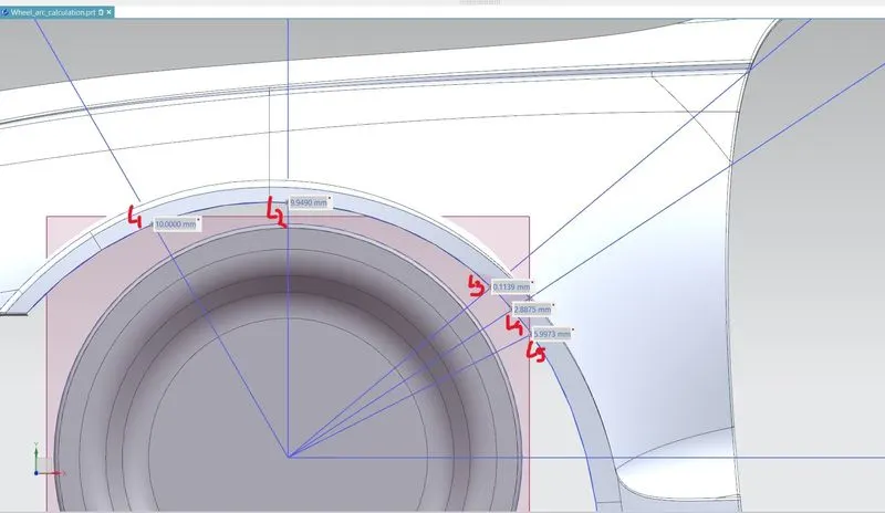
Now from the above calculation we came to know that except L1 all other values of "L" are less than 10mm. So the wheel arc design is not as per europian standard and it should be modified or corrected.
Calculation of the Clearance for Wheel Guard requirement. (a)
Fig: 3
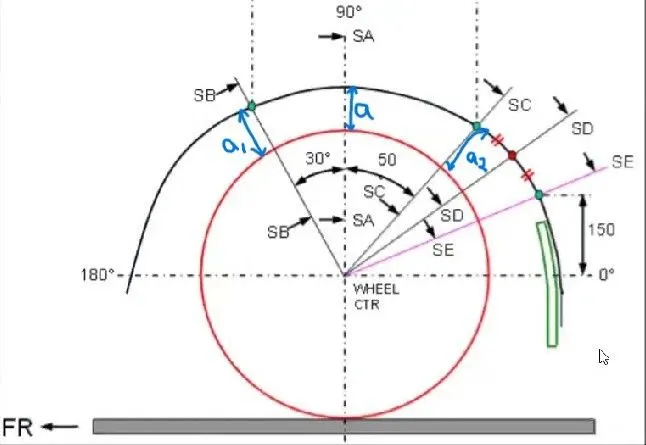
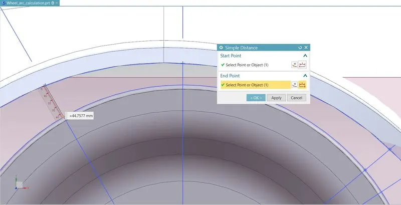
Now we have to calculate the distance between wheel and inner edge of the fender wheel arc as shown in the above fig:3. We will be calculating at 2 different points as shown above.
The value of a1 = 44.7577 mm
The value of a2 = 38.3599 mm
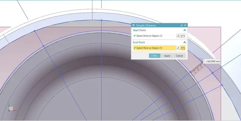
Now as per europian standard , the minimum gap should be 5mm and here both the value of "a" is more than that . So these satisfy the europian standard.
Final result of calculation : From the above calculation we can observe that the value of "a" is satisfactory at the desired positions but the value of "L" is only satified for L1 and the value at other remaining positions is less than 10mm .
As per europian standard, although the value of "a" is satisfactory ,the value of "L" should not be less than any of the 5 positions as per Fig.1.
So the given fender design is not acceptable for any of the regions i.e. USA, or Japan or Europe.
Report Prepared by: Vikash Rai