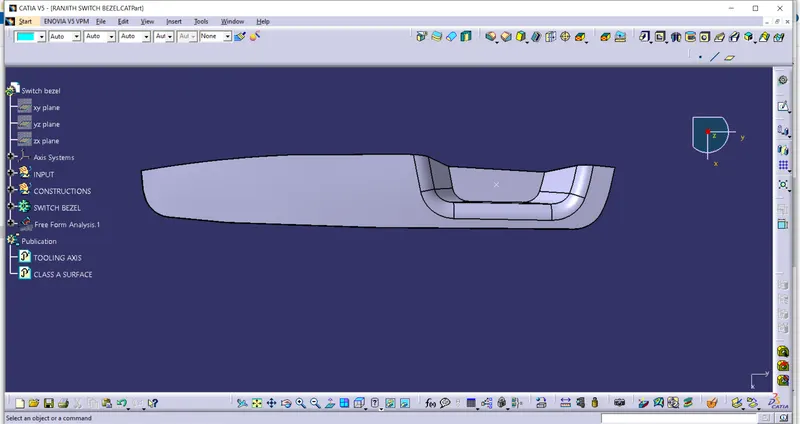
Week 9 - Challenge 2 - Switch Bezel Design
OBJECTIVE:-
The objective of the project is to design the switch bezel and to do a draft analysis for it by creating the required tooling direction with the help of Bisecting method.
Abstract:
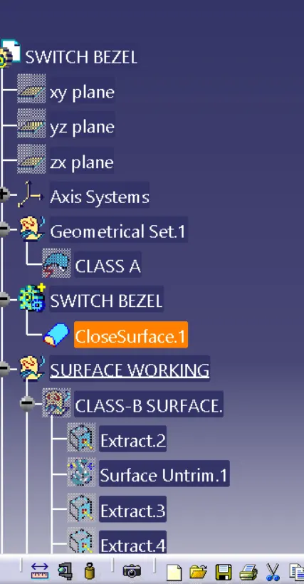
In this project, I design a Switch Bezel using Catia v5. I received input as Class A Surface. I Check the direction to eject the tool based on the component design. Later I checked whether all faces that intersected will clear the direction based on the tooling axis. I started working on the Draft Analysis tool to check if our tooling direction clears the path for easy removal of material from the tool. After that, I go class B creation using Advance tools from the surface followed by class C creation using the sweep command. after design A B C class surface, converting close surface into solid inside the part workbench.
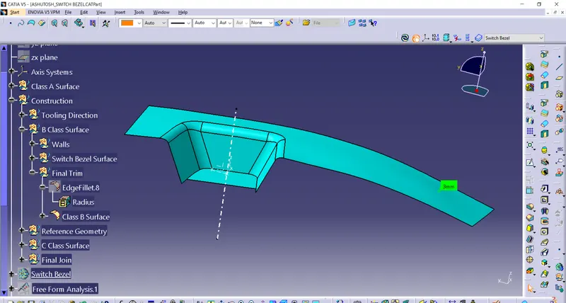
Switch bezel is a car part which contains switches and buttons to control different functions like window control. It is located at the inner portion of the door. The procedure used to create the part was same as the base bracket one. Class A surface was used to create the tooling axis. Class B surface was created at a distance equal to the thickness which was the identical surface of class A.
Class C was formed as the wall of the model and then all the three surfaces were joined together and draft analysis was carried out.
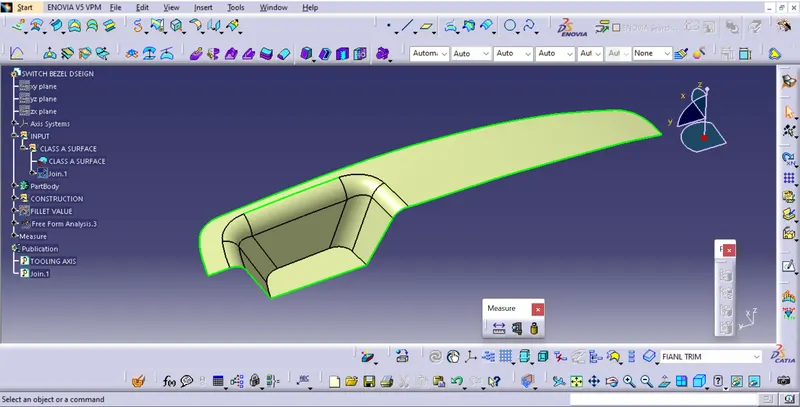
->) Steps in detail that are involved to create switch bezel are as follows:-
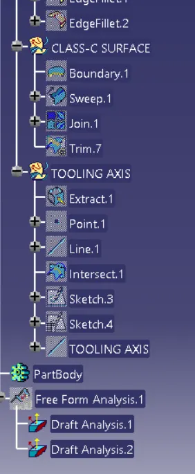
*) The first geometrical set was created with the name tooling axis and a sketch was created taking the reference of the two planes. The sketch involved two lines drawn in the the planes and then bisector of the two lines was created which was the main tooling direction.
DESIGN CONSIDERATION:
Class-A surface should be asthetically smooth and good.
Class-B surface should have all the supporting features like ribs.
Parting Line should coincide with the B surface since flashing couldn't affect the asethetic of Class-A.
Class-C surface should also pass the draft analysis.
PROCEDURE:
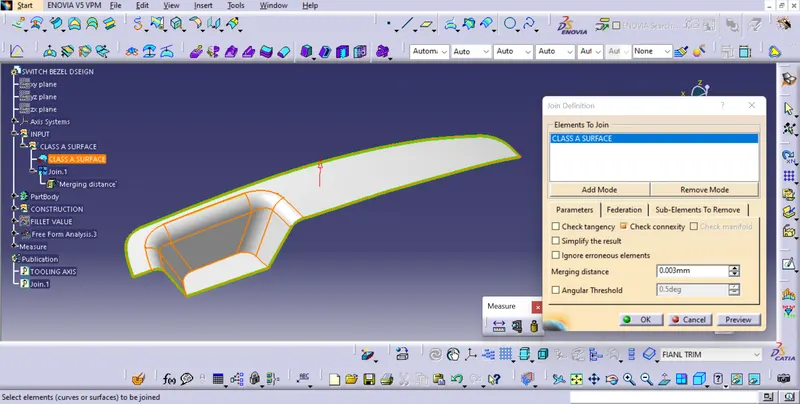
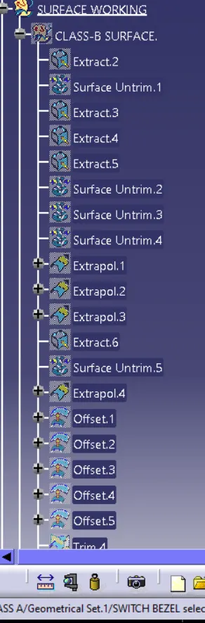
First,the given stylish surface is checked for any irregularities and if found and then it is corrected by using trim,extrapolate,split and join commands.
The below images shows that the Class-A surface is clean and no irregularities present, so let's move on to the next step.
Creating tooling axis:
The ejection from the mold after manufacturing the interior trim must have the nominal 3-degree draft angle.
hence the tooling directions created by considering the above factor and bisecting method is used.
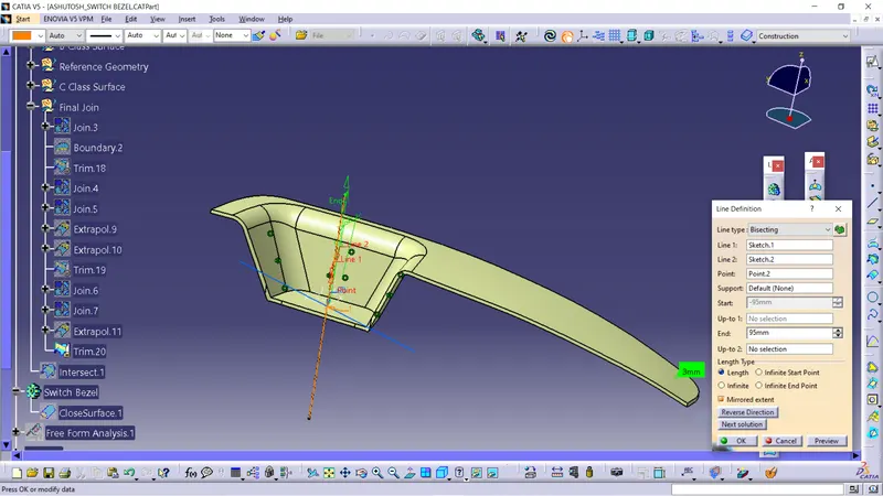
The base surface of the class-A was extracted to create a reference point on the surface using the point, create a line in the z-direction and an axis system was inserted to the point
then using projection intersection along the yz plane is created and the two inclined lines were drawn inside the positioned sketch.
then bisecting lines with the two inclined lines were created.
DRAFT ANALYSIS ON CLASS-A SURFACE:
- Go to insert> analysis> feature draft analysis
- Align the tooling axis with the compass.
- Click on the surface and see that the surface is within the permissible limit of the draft values.
- The surface should be green and in the column nominal value 3deg given as input. hence the draft analysis on the class-A surface is successfully performed.
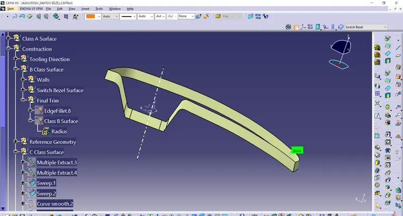
CLASS-B SURFACE CREATION:
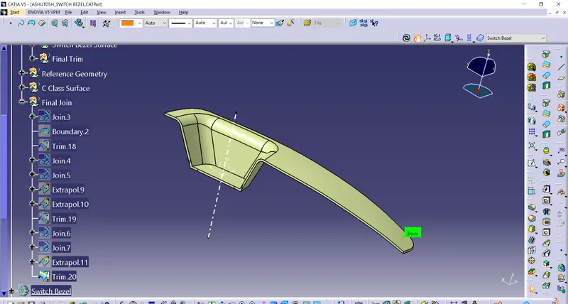
CLASS-C SURFACE CREATION:
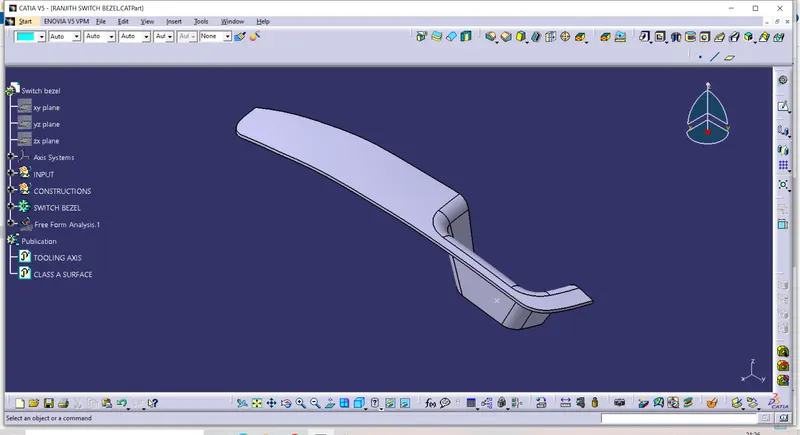
ISOMETRIC:
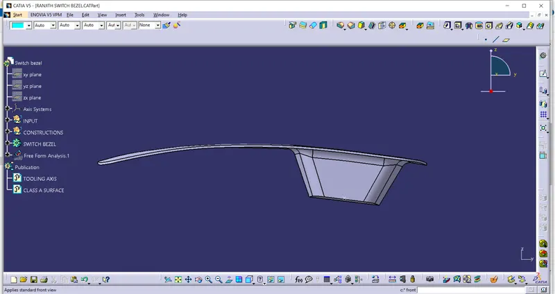
FRONT:
TOP: