Week 9 - Challenge 2 - Switch Bezel Design
------------------------------------------------SWITCH BAZEL DESIGN----------------------------------------------------
- TREE STRUCTURE
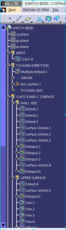
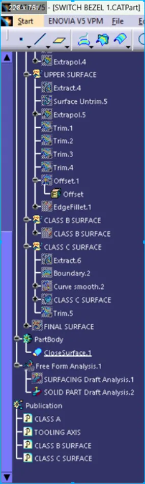
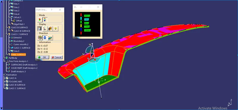
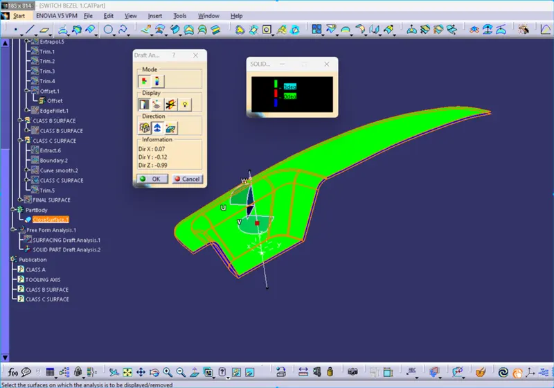
- DRAFT ANALYSIS OF CLASS A SURFACE
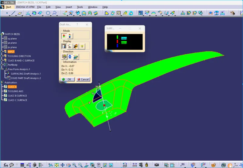
- DRAFT ANALYSIS OF FINAL PLASTIC COMPONENT
- ALL ORIENTATIONS VIEWS
FRONT VIEW
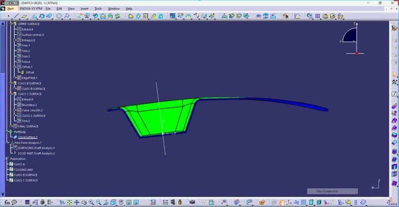
SIDE VIEW
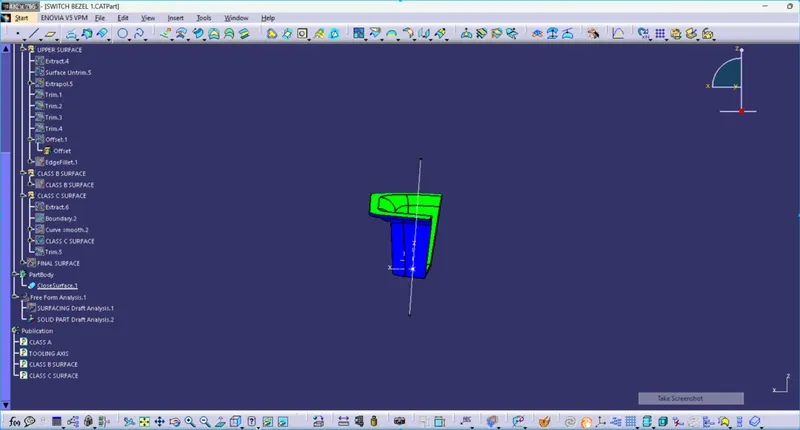
TOP VIEW
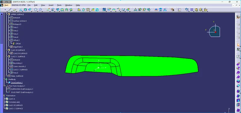
ISOMETRIC VIEW
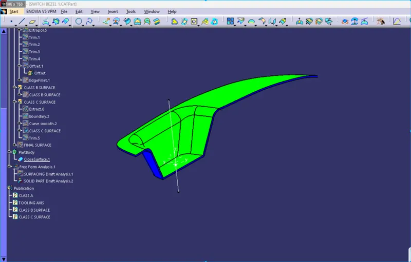
REPORT
1. Tooling Axis Creation
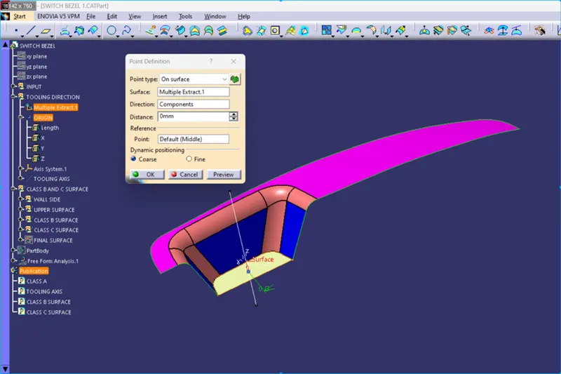
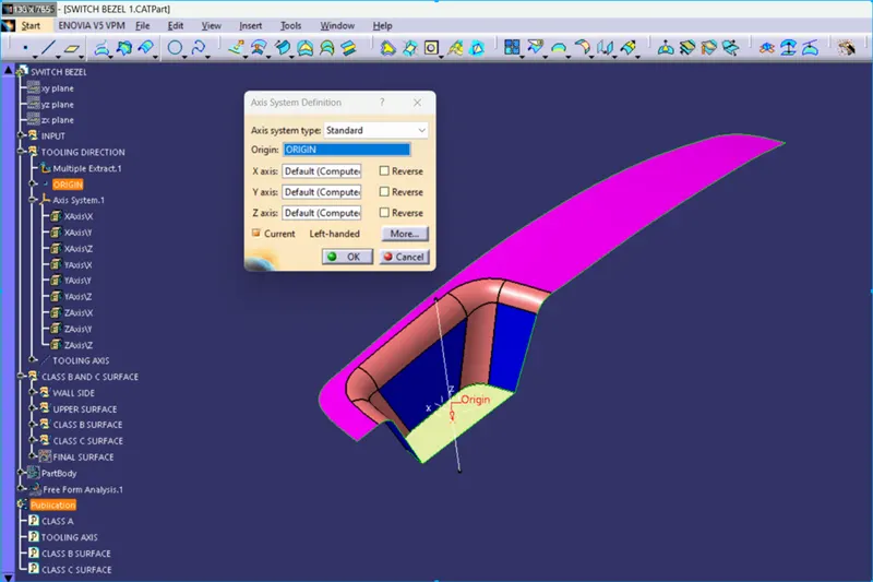
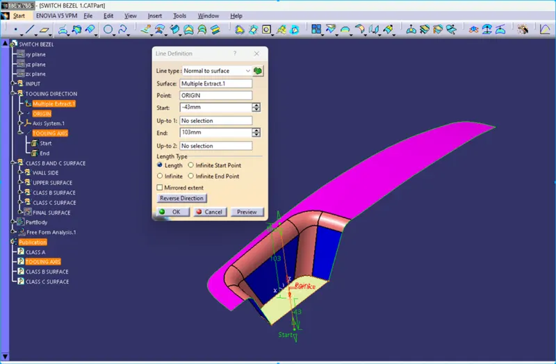
- Take the class A surface
- Extract the bottom face and create the Origin Point
- Choose the Line command and make the axis normal to the Extracted surface.
But in the bisection method, there are some errors during the draft analysis of the sidewall.
- Select the YZ plane and position Sketch
- choose Intersect 3D element and touch the class A surface, An horizontal intersect line will create.
- project the origin point to the extracted bottom surface.
- click line command (point to point) and touch both sides of 2 points which makes the draft angle.
- Choose the bisecting Line command then touch both lines.
- Now, click the XZ plane and position sketch
- choose Intersect, and touch the class A surface, with the XZ plane. An intersect line will create on the class A surface.
- click line command (point to point) and touch one side of the wall on which draft analysis has to be done.
- click the line command and sketch the line on the XZ plane which will make 3 deg angle from the side wall.
- Now, We have the 2 Tooling axis.
- so for the exact tooling axis, we will use the bisection line method.
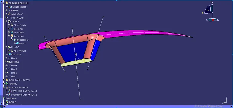
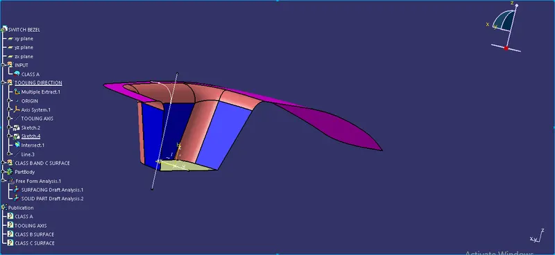
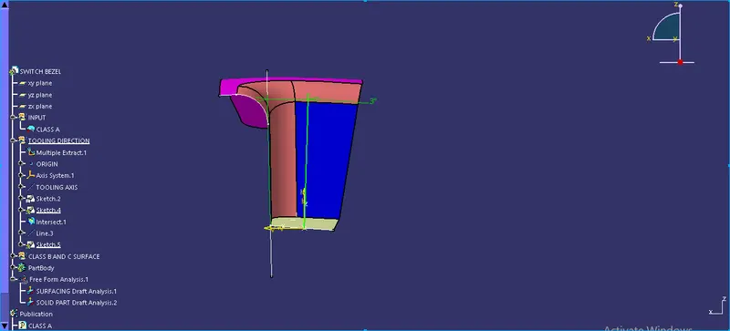
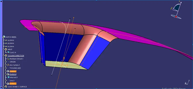
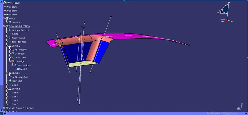
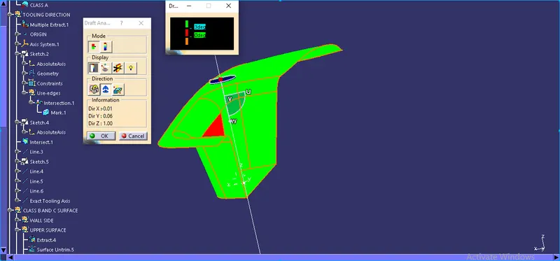
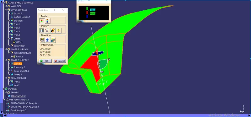
Here, Above Draft analysis, you can see that I am using the bisection method for the creation of the tooling axis, I will find
the 0 deg draft angle of one side wall of Class A surface copy. So I have used the normal to Surface line method for the creation of the tooling axis.
You can see the tree structure has also changed in the bisection method.
2. Draft analysis
- Select the Feature Draft Analysis
- click the part and define the tooling Direction
- Green Side is showing that the part will be made according to the Draft Angle which is 3 degrees and there will no erosion between the Tool and Plastic parts.
- The blue side is showing a negative Draft angle (interference) or is impossible to draw the part according to the draft angle.
Total Draft Analysis