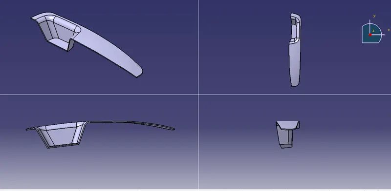
Week 9 - Challenge 2 - Switch Bezel Design
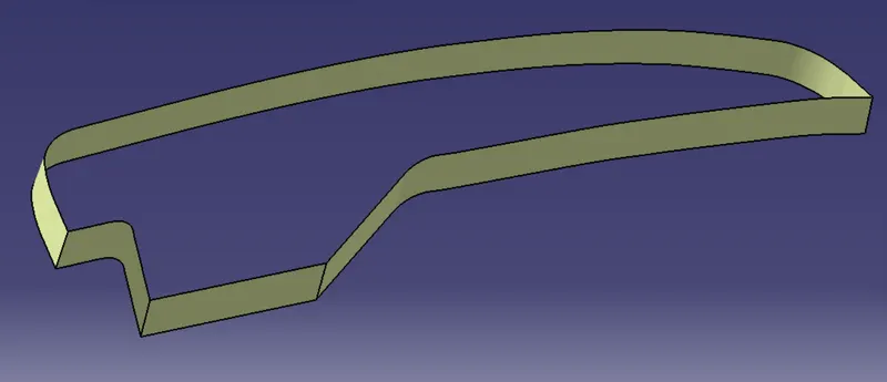
Aim: Create the Switch Bezel Plastic component through the given Class-A surface. To begin with, the tooling axis for the given Class-A surface should be created meeting the requirements of draft angle and at the end perform the Draft analysis on the model.
Objective:
To create class B & C surface for the given component.
- To form the tooling axis and capture the surface properly.
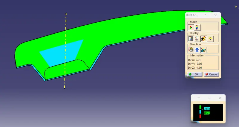
- To check the feasibility of the component with draft of 3 degrees.
Method:
Tooling axis direction:
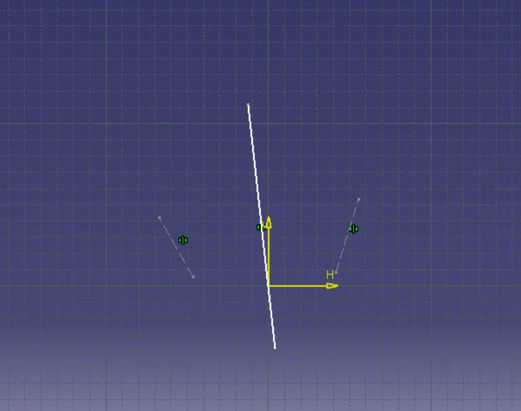
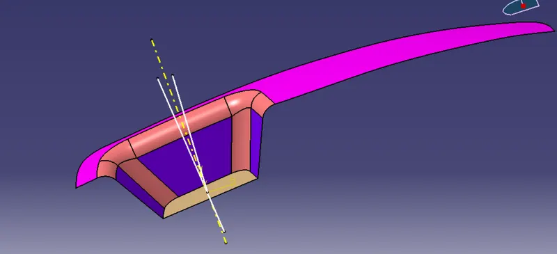
- As this component has 1 hole from where the tooling axis can generate, however it does not have proper 4 walls to generate it. In this case, an approximation is made in order to obtain the tooling axis.
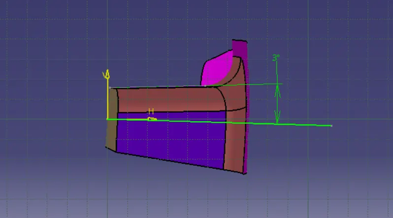
- First by using the two side walls a dummy axis made. As it is known that draft angle is 3 degrees, the second axis is taken as a 3 degree to the given wall and using these two axis the tooling is made.
- creating the tooling axis, particularly the Bisecting method for sketch 1 and sketch 2 show below.

Class-A surface:
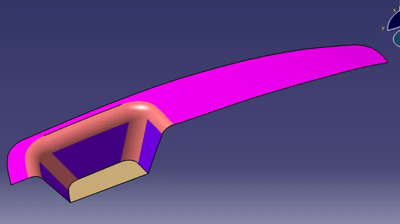
- Check class-A surface opening for planarity.
- Boundary creates for class-A surface one side.
- Join operation command use for in merging distance 0.003mm.
Class-B surface:
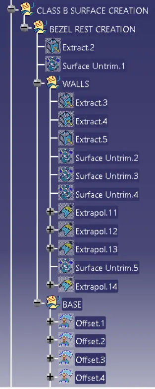
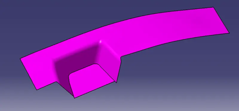
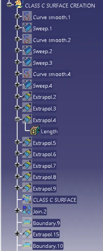
Class-C surface:
Draft Analysis:
draft angle for 3 degrees.
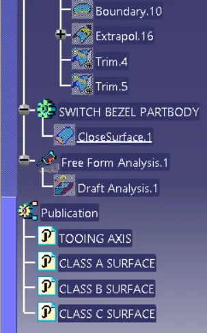
Final part: 2.5mm thickness