Week 9 Challenge
AIM:
Create the core-cavity, slider blocks & Undercuts for the given component
PROCEDURE
STEP-1: Deciding the tooling direction
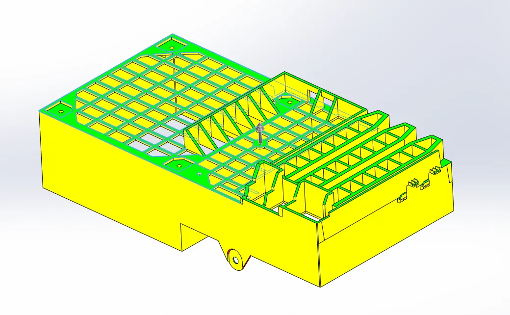
- Selected the tooling direction which leads to minimum udercuts
- done draft analysis to check adequate drafts in the model
- core
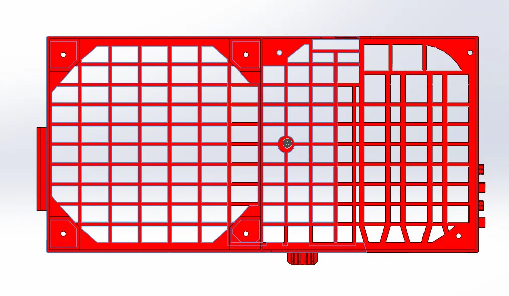
- cavity
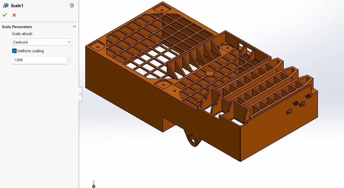
STEP-2: Scaling the model
Increased the model size by 0.6% to account shrinkage because ABS material shrinkage % is 0.6%
calculation
(0.6/100)+1 = 1.006
so 1.006 is the scaling value
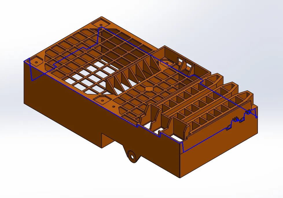
STEP-3: Creating parting line
It is a core & cavity separating line or core and cavity meets at this line
STEP-4: Creating sutt-off surface
To close the holes and to create the core cavity surfaces
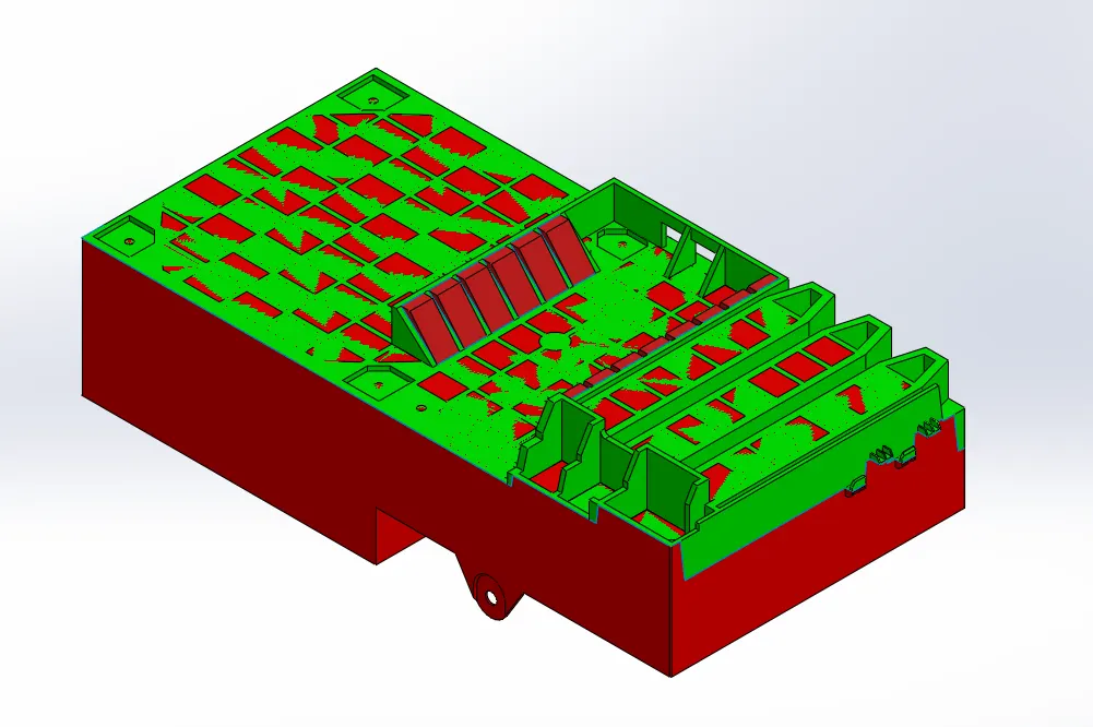
STEP-5: Creating the parting surfce
Surface which separates the core and cavity into 2 blocks in a mould
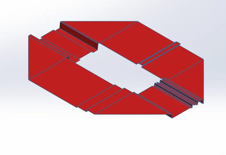
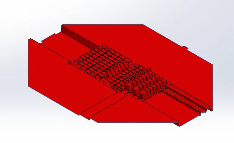
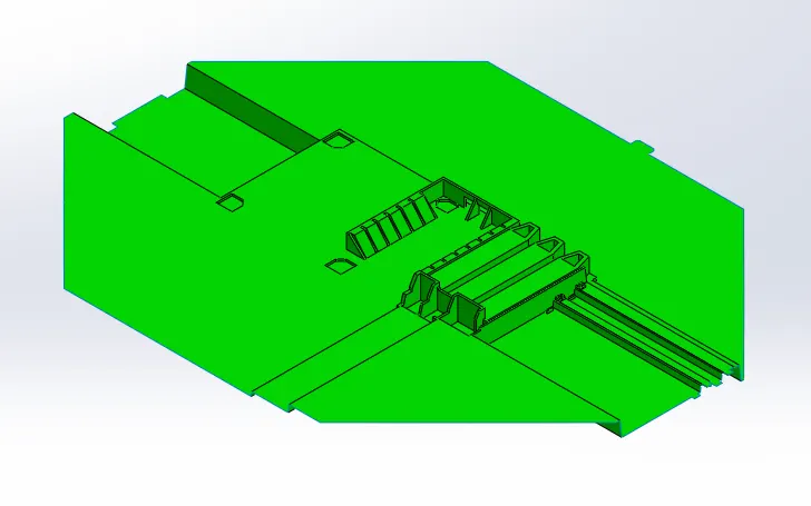
STEP-6: Creating core and cavity surfaces
Merge the parting surface with core and cavity surfaces
core surface
cavity surface
STEP-7: Creating core and cavity blocks
CORE
- Edited the core block to match the slider block.
- Created guide rails in core block.
- Make a cut in the core block for bolts.
CAVITY
- Edited the cavity block to match the slider block.
- Edited cavity block as per rib rails.
- Edited cavity as per slider cuts.
- edited as per washers and gave 1mm relief.
SLIDERS
- Slider block is needed to accomodate the finger cam & washers
- using split command sepereted the slider profile from cavity block
- create the slot like feature in the component to make he hole in the part.
- filled the gap in the slider
- 40 mm slider is enough,cuted out the remaining.
- created slider block in such a way that it shouldn't itersect with the component by providing suitable gap allowance
- created wedge to properly interlock with the cavity block.
- crated the guide rails in the slider block.
- by calculating slider travel distance made a cut for locking mechanism.
- saved the slider separately and added in the assembly
CONCLUSION
Created the core,cavity block & slider with proper dimensions for the given model