Week 9-Challenge
Objective:
To mesh the frame assembly and make connection representation at specified parts.
Required connections:
1. Right_Rail_2 & Front_truss_1:- Seam-Quad(angled+capped+L)
2. Left_Rail_2 & Front_truss_1:- Quad elements
3. Front_truss_2, Front_truss_1 & Right_Rail_1:- Spot weld with 3 Layers and 5 mm Diameter
4. Front_truss_2, Front_truss_1 & Left_Rail_1:- Hexa (Adhesive)
5. Rear_truss_2 & Right_Rail_2:- Bolt Connector
6. Rear_truss_2 & Left_Rail_2:- Bolt Connector
7. Right_Rail_1 & Right_Rail_2:- Spot-weld with Rigid Elements
8. Left_Rail_1 & Left_Rail_2:- Spot-weld with Spring Elements
9. Rest all the component left Join them with suitable connectors
Procedure:
Case setup & Execution:
- The given Frame assembly model is opened into hypermesh under opistruct profile.
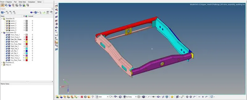
- Since the given Frame model is an Extracted midsurface free of geometrical errors we can directly proceed to meshing.
- Meshing can be done by auto mesh option available in 2D panel with a target element size of 5mm to each component individually
- After meshing the mesh quality is also checked using check elements option available in tools panel
- To achieve smooth mesh flow, smooth option SHIFT+F2 is clicked on the keyboard then the elements needed to be smoothed is selected.
Meshed frame model:
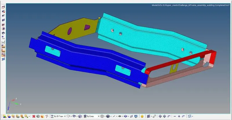
CONNECTIONS:
1. Right_Rail_2 & Front_truss_1:- Seam-Quad(angled+capped+L)
- In 2D panel connector is selected, then from the list of available options Seam option is Selected.
- Only Right_Rail_2 & Front_truss_1 is made to be visible all other components are hidden.
- Now in the seam weld creation menu bar, seam type is chosen as "Seam-Quad(angled+capped+L)"
- The node list is selected with a line spacing of 5mm, then the components to be connected is selected after which create option is clicked to deploy the seam-quad(angled+capped+L) connection.
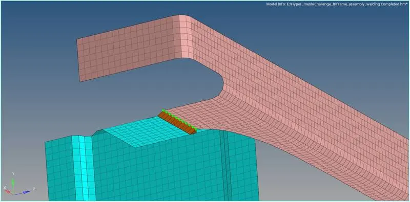
2. Left_Rail_2 & Front_truss_1:- Quad elements
- In 2D panel connector is selected, then from the list of available options Seam option is Selected.
- Only Left_Rail_2 & Front_truss_1 is made to be visible all other components are hidden.
- Now in the seam weld creation menu bar, seam type is chosen as "Seam-Quad"
- The node list is selected with a line spacing of 5mm, then the components to be connected is selected after which create option is clicked to deploy the seam-quad connection.
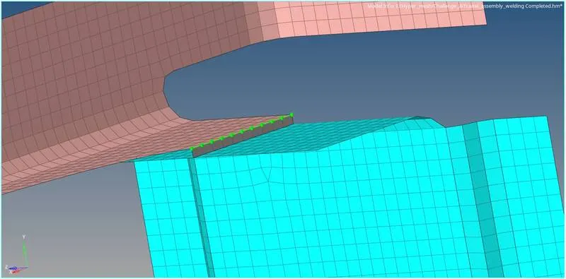
3. Front_truss_2, Front_truss_1 & Right_Rail_1:- Spot weld with 3 Layers and 5 mm Diameter
- In 2D panel connector is selected, then from the list of available options, Spot option is Selected.
- Only Front_truss_2 , Front_truss_1 & Right_Rail_1 is made to be visible all other components are hidden.
- Now in the spot weld creation menu bar, seam type is chosen as "Spot-weld"
- The node list is selected with a line spacing of 5mm, then the components to be connected is selected then number of layers is specified as 3 after which create option is clicked to deploy the Spot- Weld connection.
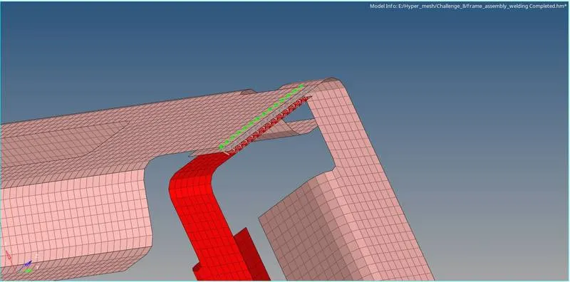
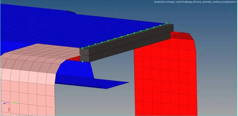
4. Front_truss_2, Front_truss_1 & Left_Rail_1:- Hexa (Adhesive)
- In 2D panel connector is selected, then from the list of available options Seam option is Selected.
- Only Front_truss_2 , Front_truss_1 & Left_Rail_1 is made to be visible all other components are hidden.
- Now in the seam weld creation menu bar, seam type is chosen as "Seam-Hexa (Adhesive)"
- The node list is selected with a line spacing of 5mm, then the components to be connected is selected with a width of 5mm is given after which create option is clicked to deploy the seam-Hexa (Adhesive) connection.
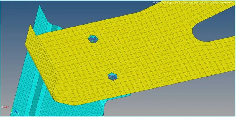
5. Rear_truss_2 & Right_Rail_2:- Bolt Connector
- In 2D panel connector is selected, then from the list of available options bolt option is Selected.
- Only Rear_truss_2 & Right_Rail_2 is made to be visible all other components are hidden.
- Now in the bolt creation menu bar, seam type is chosen as general
- The nodes is selected with a tollerance of 50 and number of layers as 2 , then the components to be connected is selected after which create option is clicked to deploy the bolt connection.
6. Rear_truss_2 & Left_Rail_2:- Bolt Connector
Similar method followed in the above is used to deploy the bolt connectors on Rear_truss_2 & Left_Rail_2
7. Right_Rail_1 & Right_Rail_2:- Spot-weld with Rigid Elements
- In 2D panel connector is selected, then from the list of available options, spot option is Selected.
- Only Right_Rail_1 & Right_Rail_2 is made to be visible all other components are hidden.
- Now in the spot weld creation menu bar, seam type is chosen as "Spot-Rigids"
- The node path is selected with a line spacing of 5mm, then the components to be connected is selected then number of layers is specified as 2 after which create option is clicked to deploy the Spot-weld with rigid elements connection.
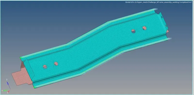
8. Left_Rail_1 & Left_Rail_2:- Spot-weld with Spring Elements
- In 2D panel connector is selected, then from the list of available options, spot option is Selected.
- Only Left_Rail_1 & Left_Rail_2 is made to be visible all other components are hidden.
- Now in the spot weld creation menu bar, seam type is chosen as "Spot-springs"
- The node path is selected with a line spacing of 5mm, then the components to be connected is selected then number of layers is specified as 2 after which create option is clicked to deploy the Spot-weld with Spring elements connection.
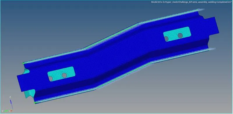
9. Remaining Components are connected using spot welds and seam weld with the above mentioned procedure
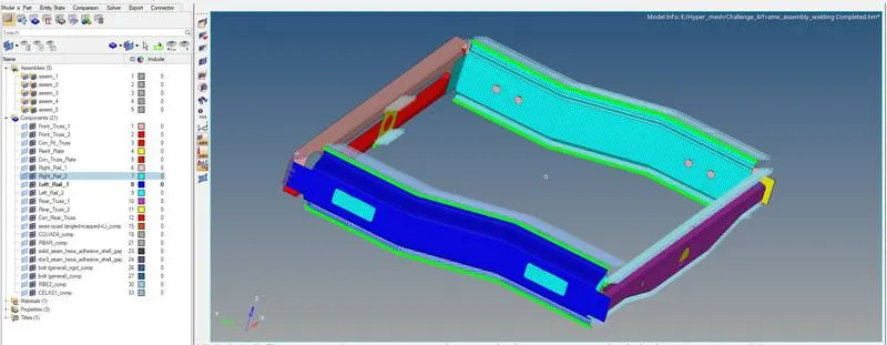
Final Model Image:
Conclusion:
The given frame assembly model is meshed and the different connectors are deployed on the mesh to understand the various process involved in the creation of connections.