COMPARISON OF BASE SIMULATION WITH RECOMMENDED SHELL ELEMENT PROPERTIES
Objective:
To compare base simulation and improved shell element properties:
1.Using the crash beam file from the previous assignment, change the run time to 55 ms.
2.Change the number of animation steps using simulation to a minimum of 25 and maximum of 60.
3.Run the base simulation without any modification to element properties.
4.At the end of the simulation, do the energy error and mass error checks and determine whether results would be acceptable.
5.If acceptable, Plot rigid wall forces, internal energy, hourglass energy, contact energy, total energy of the simulation.
6.Change all the shell elements properties to recommended properties, save this as separate rad files and run the simulation.
7.Follow step 5 and 6.
8.Create a brief report comparing all the results from step 5 and 6 for both simulations.
9.Comment whether there is any change in the results and why there is any change in the result.
Solution:
Case:1
Procedure:
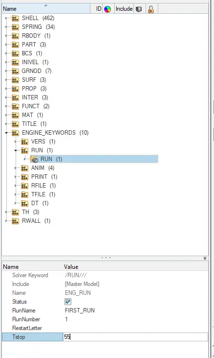
1). Using the crash beam file from the previous assignment, Change the run time to 55 ms.
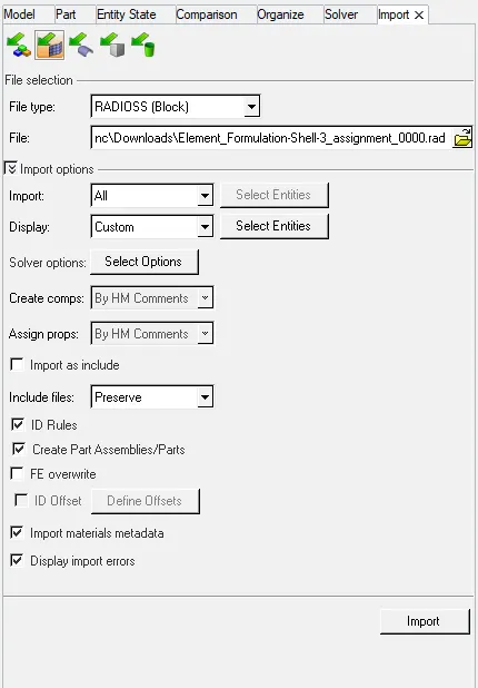
Step 1: Import the file "Element_Formulation-Shell-3_assignment_0000" in hypermesh.
Step 2: To edit the engine file to change the runtime to 55 ms. the following steps are used:
View `rarr` Browser `rarr` Hypermesh `rarr` Solver `rarr` Engine `rarr` Run
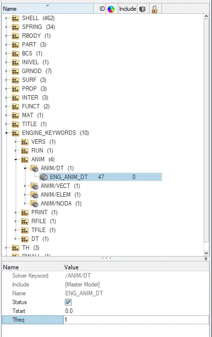
2).To change the number of animation steps during the simulation to a minimum of 25 and maximum of 60.
here we can take the number of steps between 25 and 60, let us take 55
Therefore frequency = 55/55 = 1
To edit the engine file to the frequency to 1. the following steps are used:
View `rarr` Browser `rarr` Hypermesh `rarr` Solver `rarr` Engine `rarr` Anim
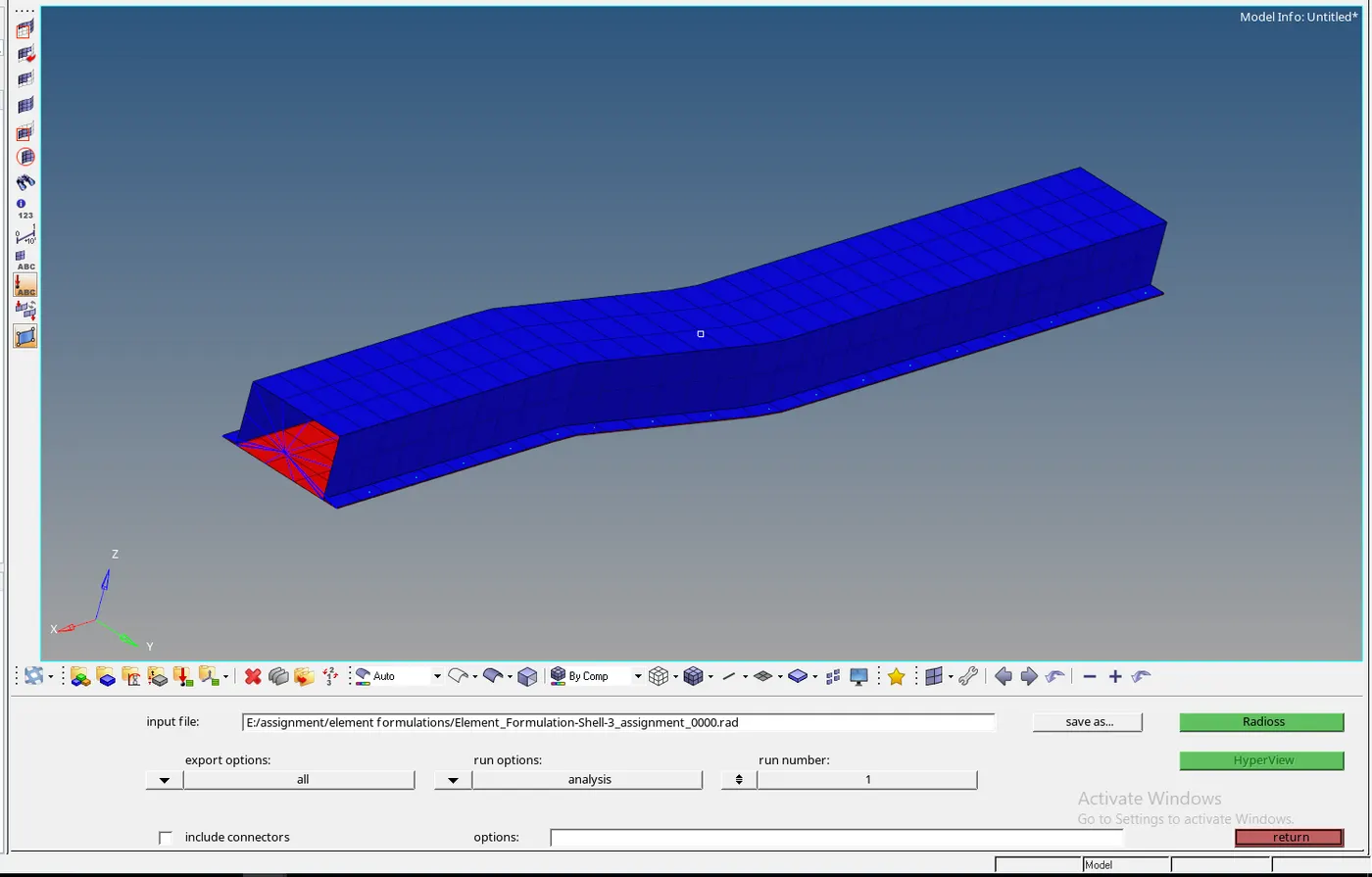
3). Run the base simulation without any modification to the element properties.
Step 1: Click on the analysis panel in the hypermesh.
Step 2: Save the model in the local directory.
Step 3: Click the RADIOSS button the run the base simulation.
4). At the end of the simulation, do the energy error and mass error checks and determine whether the results would be acceptable.
To check the energy and mass error we have to open the file "Element_Formulation-Shell-3_assignment_0001" in a text editor.
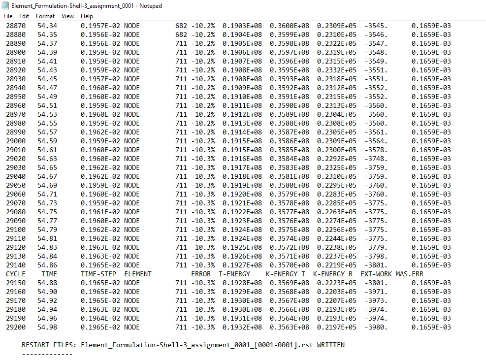
as the energy error is -10.3% which is less than -15% so it is acceptable, also the mass is found out to be 0.1659E-03.
5). If acceptable plot rigid wall forces, internal energy, hourglass energy, contact energy, total energy of the simulation.
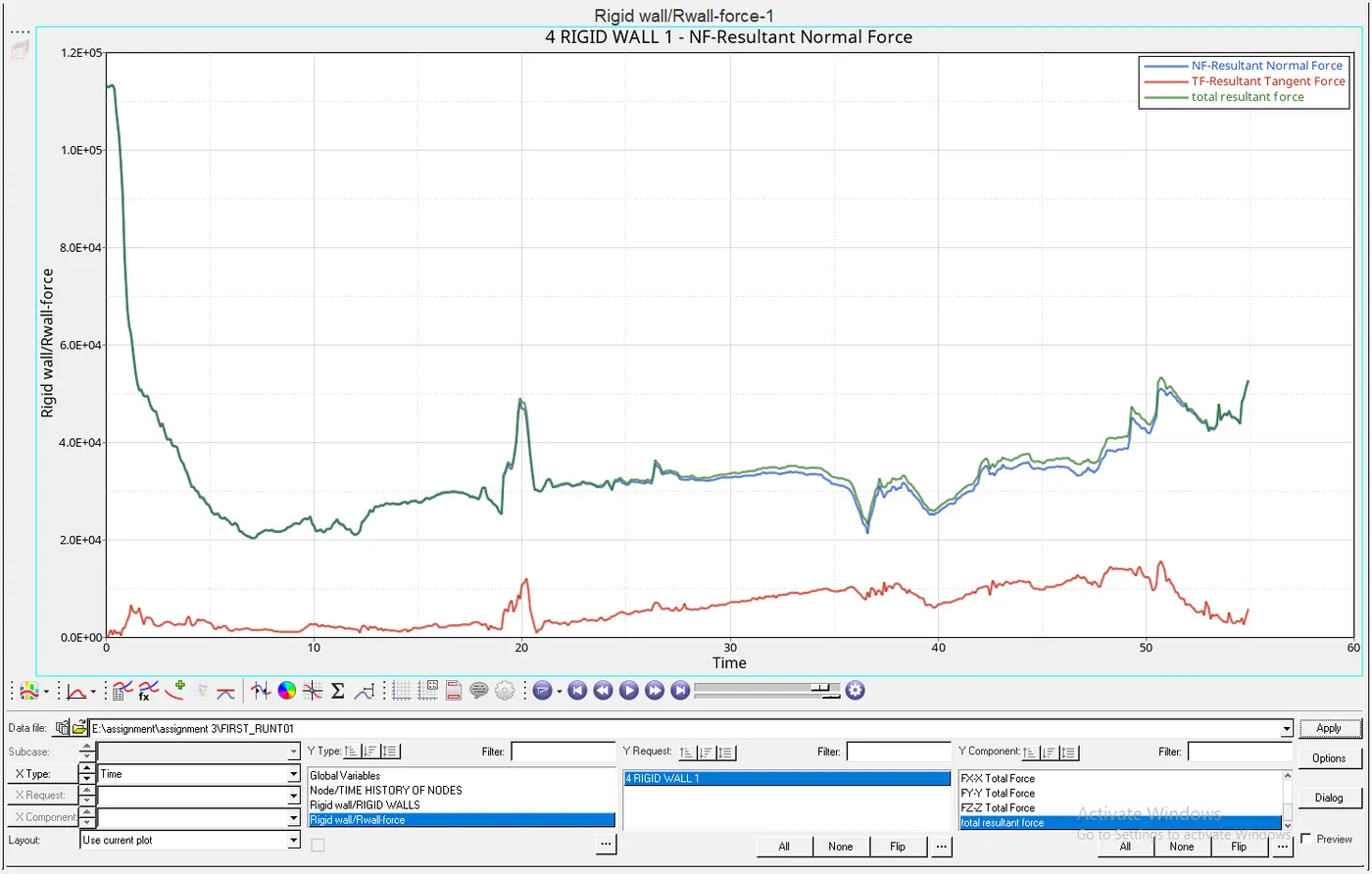
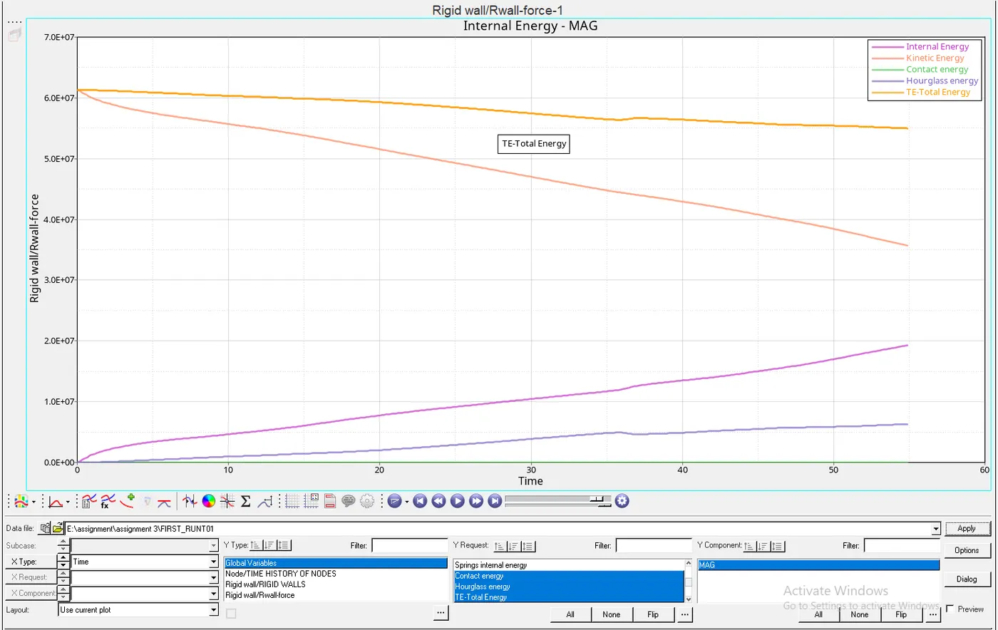
since the energy error is acceptable we can proceed to plot the graph by changing the environment to Hyperview, then importing the file "Element_Formulation-Shell-3_assignment.h3d"
After which to plot the graph Hypergraph 2D is launched in a separate screen in which "Element_Formulation-Shell-3_assignmentT01" file is opened to view all the energy graph with respect to time.
Case 2:
6). Change all the shell elements properties to recommended properties, save this as separate rad files and run the simulation.
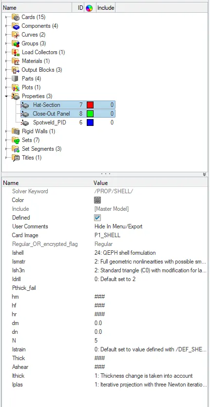
Recommended Properties as Follows:
| Parameters | Comment |
| Ishell=24 | QEPH 4-noded shells are the best combination of cost and accuracy |
| Ismstr=2 | Full Geometric nonlinearities (default) with possible small strain formulation activation in RADIOSS Engine |
| Ish3n=2 | Standard 3-noded shell (C0) with modification for large rotation (default) |
| N=5 | Number of integration points set to 5 for accuracy in bending |
| Ithick=1 |
Thickness change is taken into account for accuracy |
| Iplas=1 | Iterative plasticity for good accuracy |
Now open a new hypermesh window with the same file "Element_Formulation-Shell-3_assignment_0000"
Now run the model as per Step 3 and save it in a separate location.
7). Follow steps 4 and 5:
To check the energy and mass error we have to open the file "Element_Formulation-Shell-3_assignment_0001" in a text editor.
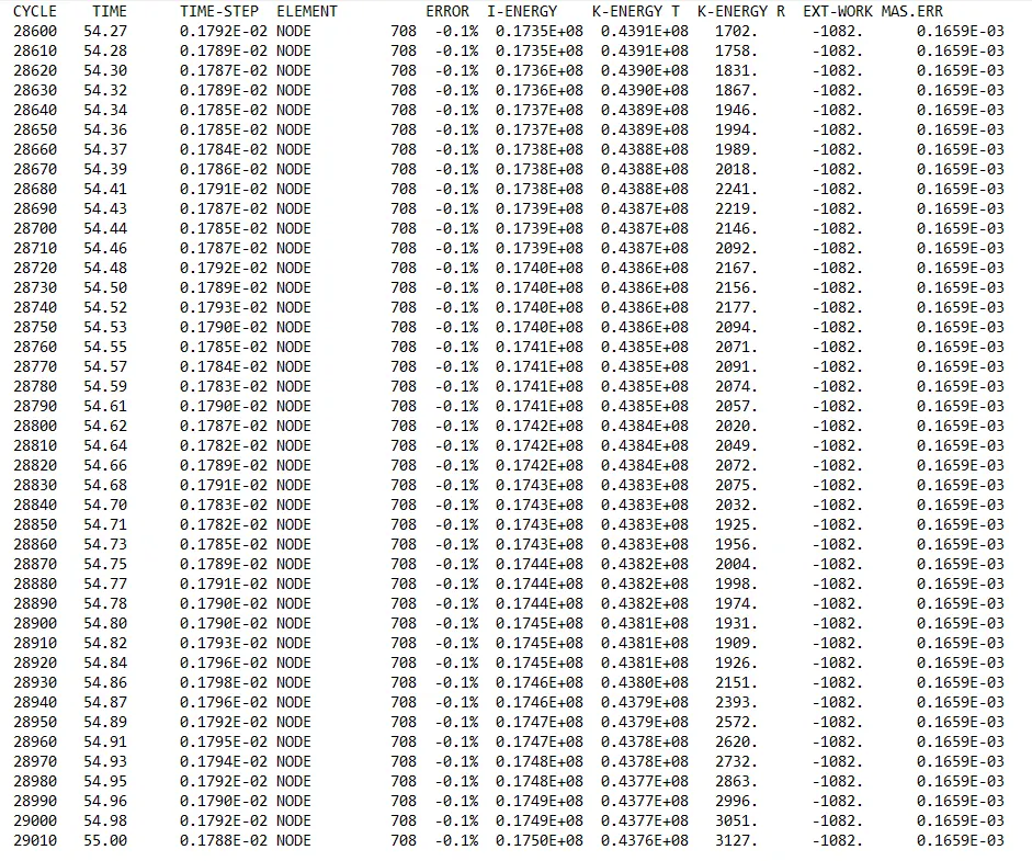
as the energy error is -0.1% which is less than -15% so it is acceptable, also the mass is found out to be 0.1659E-03.
since the energy error is acceptable we can proceed to plot the graph by changing the environment to Hyperview, then importing the file "Element_Formulation-Shell-3_assignment.h3d"
After which to plot the graph Hypergraph 2D is launched in a separate screen in which "Element_Formulation-Shell-3_assignmentT01" file is opened to view all the energy graph with respect to time.
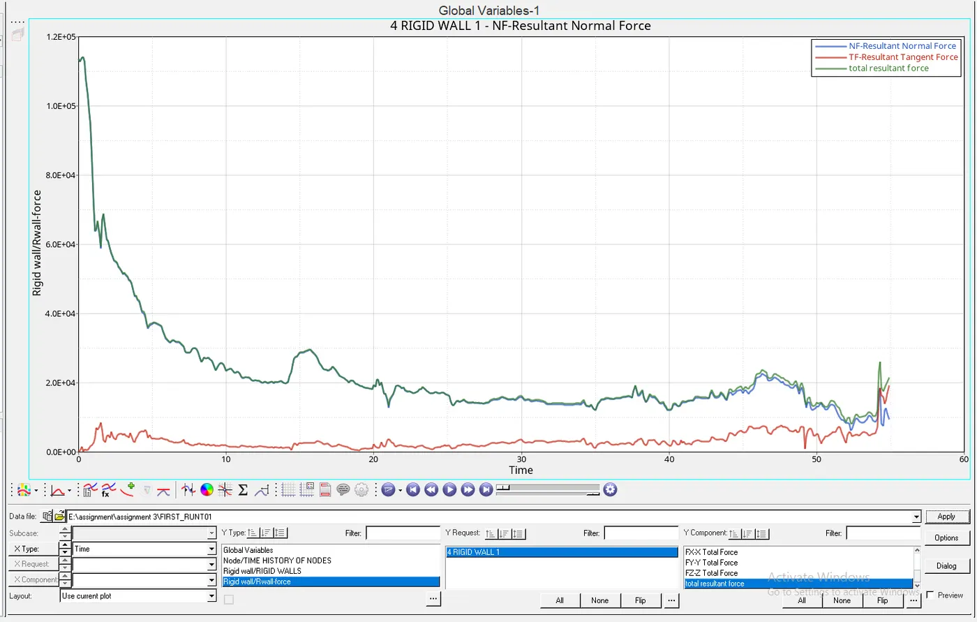
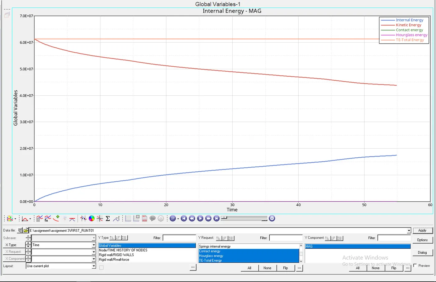
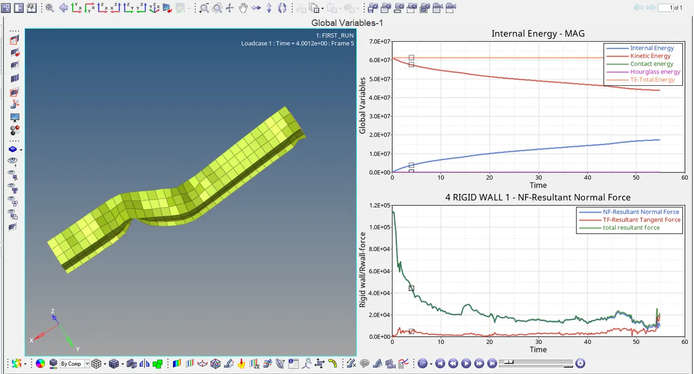
8). Create a brief report comparing all the results from step 5 and 6 for both simulations.
| RESULTS | Simulation Without Change in properties | Simulation of Recommended properties | Remarks |
| Energy error | Final value -10.3% | Final value -0.1% | the energy error decreases with a change in property values. |
| Mass error | Final value 0.1659E-03 | Final value 0.1659E-03 | mass error remains the same in both cases |
| Rigid wall forces | - | - | No more change in resultant tangent forces but total resultant and resultant normal force changes. |
| Internal Energy |
Initial value : 0 Final value : 1.93E+07 |
Initial value : 0 Final value : 1.93E+07 |
Internal energy increases gradually over time in both cases. |
| Kinetic Energy |
Initial value : 6.13E+07 Final value : 3.57E+07 |
Initial value : 6.13E+07 Final value : 4.15E+07 |
Kinetic energy drops in both cases, but the decrease in energy is higher in simulation without change in property values. |
| Contact energy |
Initial value : 0 Final value : 2.55E+04 |
Initial value : 0 Final value : 6.14E+03 |
Energy is increased gradually in without change in property model. |
| Hourglass energy |
Initial value : 0 Final value : 6.30E+06 |
Initial value : 0 Final value : 0 |
Energy change is found only in the simulation without change in property values, whereas no energy is formed in the recommended properties changed model. |
| Total Energy |
Initial value : 6.13E+07 Final value : 5.50E+07 |
Initial value : 6.13E+07 Final value : 6.13E+07 |
Energy is decreasing gradually in simulation whose properties are not changed but it remains constant in the simulation whose properties are changed to recommended values. |
9). Comment whether there is any change in the results and why there is any change in the result.
A decrease in energy error is observed when comparing the results of both simulation, the energy error is observed in simulation whose properties are not changed because of the presence of hourglass energy.
Hourglass energy:
- Reduced integration can lead to a non-physical zero-energy modes called hourglass modes.
- Normal value of hourglass energy is 10% to 15% of total energy when using under integrated element.
To avoid high hourglass energy:
- Set recommended parameters for the property definition
- HEPH for solid elements.
- QEPH for shell elements.
Two methods used to control the formation of hourglassing:
- Perturbation (Q4 Elements)
- Physical stabilization (QEPH Elements)
Hourglass Perturbation (Viscous) Control method :
- Hourglass deformation is detected with the relative motion of the nodes.
- When hourglassing is detected, a force is applied on the node to stabilize the deformation.
- This force is defined according to the element stiffness.
- This force introduces artificial energy.
Stiffness method:
- Hourglass yield depends on natural yield.
- Hourglass loading stiffness depends on natural tangent modulus.
- The hourglass treatment is done at material level.
Result and Conclusion:
Since Ishell=24 ( Recommended shell property for crash applications) is used, stiffness method is implied to control hourglass effect. therefore there is no or minimal hourglass effect is found in the second model, which is found to be more accurate.