3D Meshing using Hypermesh
Objective:
To create 2D and 3D mesh for the given components and to solve the following questions
Procedure and answers as follows:
1.Material property of the rail component can be checked in the .0000 file, Density `rho`= 0.0078 `g/(mm^2)` and youngs modulus E = 210000 `g/((ms^2)(mm^2))`, the units are taken as given in the engine file.
by these two data, we can calculate the speed of sound `C=sqrt(E/rho)`
`implies` Speed of sound C=5188.745 ms.
2.To calculate the time taken by a shock wave to travel from one end of the rail to the other.
Time taken by the shock wave to travel from one end of the rail to the other is `delt`
we know that `delt=l/c`,
where it the given that the length of the rail 'l' is 10000 mm and C=5188.745 ms.
`implies` `delt=`0.192 ms .
3.Time taken by sound to travel the length of the rail = 0.192 ms.
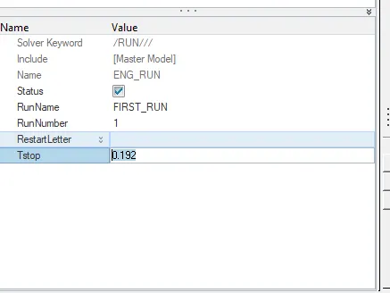
4.To edit the engine file so that the stress wave can be monitored, moving from one end of the rail to the other during impact
Termination time is equal to the time taken by the sound to travel the length of the rail = 0.192 ms.
this can be done by the following steps :
View`rarr`Browser`rarr`Hypermesh`rarr`solver`rarr`Engine`rarr`Run
5.To set the frequency of animation output to a time that will give 20 animation steps.
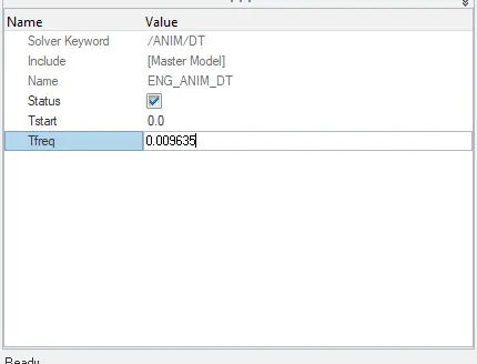
Now to find the frequency value which gives us 20 animation files on 0.192 ms.
"No of animation files = runtime/frequency"
`implies` Frequency = 0.192/20
`implies` Frequency = 0.009635.
the frequency value is given through the following steps:
View`rarr`Browser`rarr`Hypermesh`rarr`solver`rarr`Engine`rarr`Run
Here we get 20 files by which we can create animation.
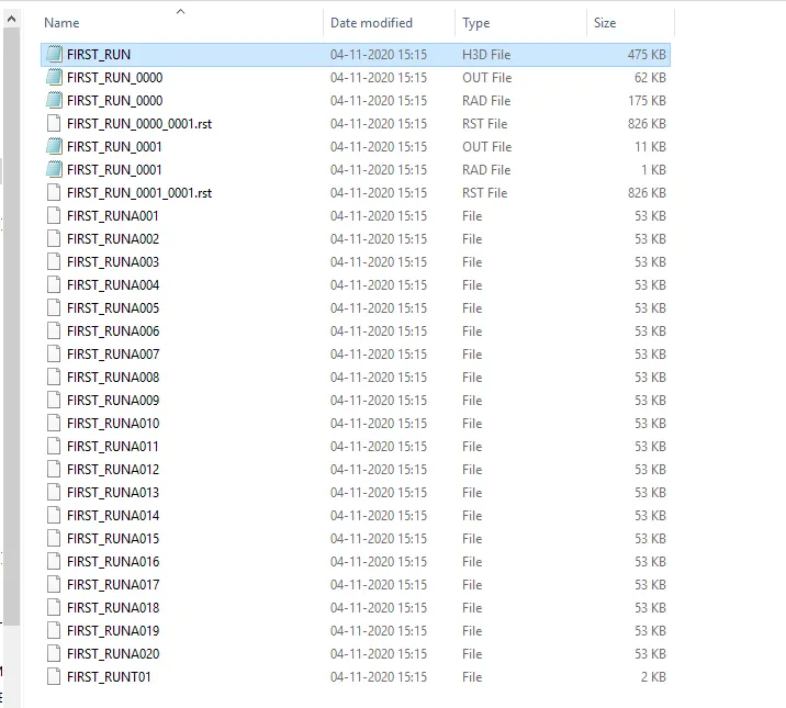
6. Charge/print -10, Printout cycle frequency is -10.
this can be noted in run0001 out File.
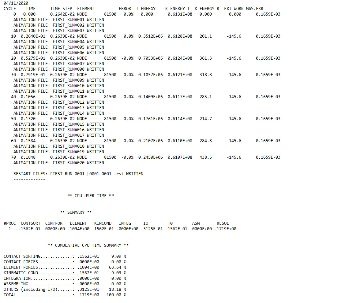
7 & 8. To perform 2D and 3D meshing on the given two components and to check the quality criteria.
1.Housing model
2.Arm bracket model .
Procedure:
For housing model:
1.First the housing model is imported into HyperWorks, It has two parts namely cover and hub.
2.The given model is checked for geometrical errors initially the proceeded for meshing.
3.In 2D meshing panel Automeshing option is selected, the surface to be meshed is selected then element size is given as 5 mm and mesh type is selected as quads only then the part is meshed.
4.The meshed part is then checked for quality such as min length, max length, aspect, skew, jacobian, warpage, tria angle and quad angle. once the necessary repair action is carried out to clear the quality criteria the part is proceeded for 3D meshing.
5.In 3D meshing panel tetra mesh option is selected, from which tetra mesh parameters such as yet collapse value 0.15 is given.after which the elements to be meshed is selected and meshed as a new volume of 3D mesh is created.
6.The created 3D volume mesh is checked for quality criteria such as tet collapse which is less than 0.15 using check elements option.
7.The 2D mesh which is created along the process needed to be deleted using F2(Keyboard shortcut for delete)
F2`rarr`elements`rarr`by config `rarr`hex8 `rarr`select entities `rarr`delete entities.
8.Mask option F5(Keyboard shortcut) is used to check whether the components have properly meshed.
Fig 1 and 2 : Given model of cover and hub.
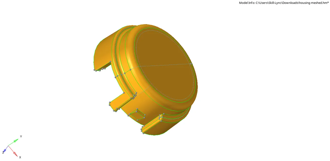
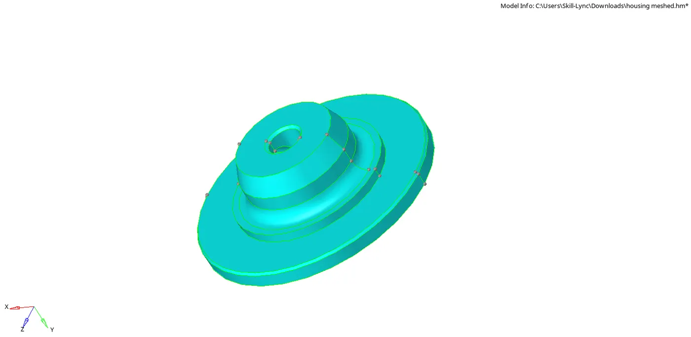
Fig 3 and 4: Meshed models of the cover and hub.
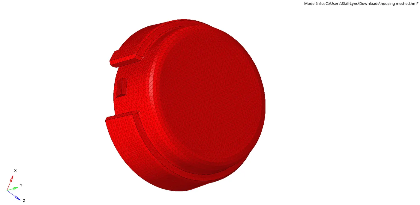
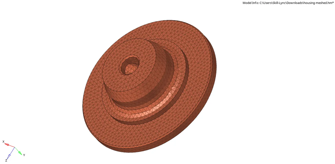
Fig 5: Masked model of the 3D meshed components.
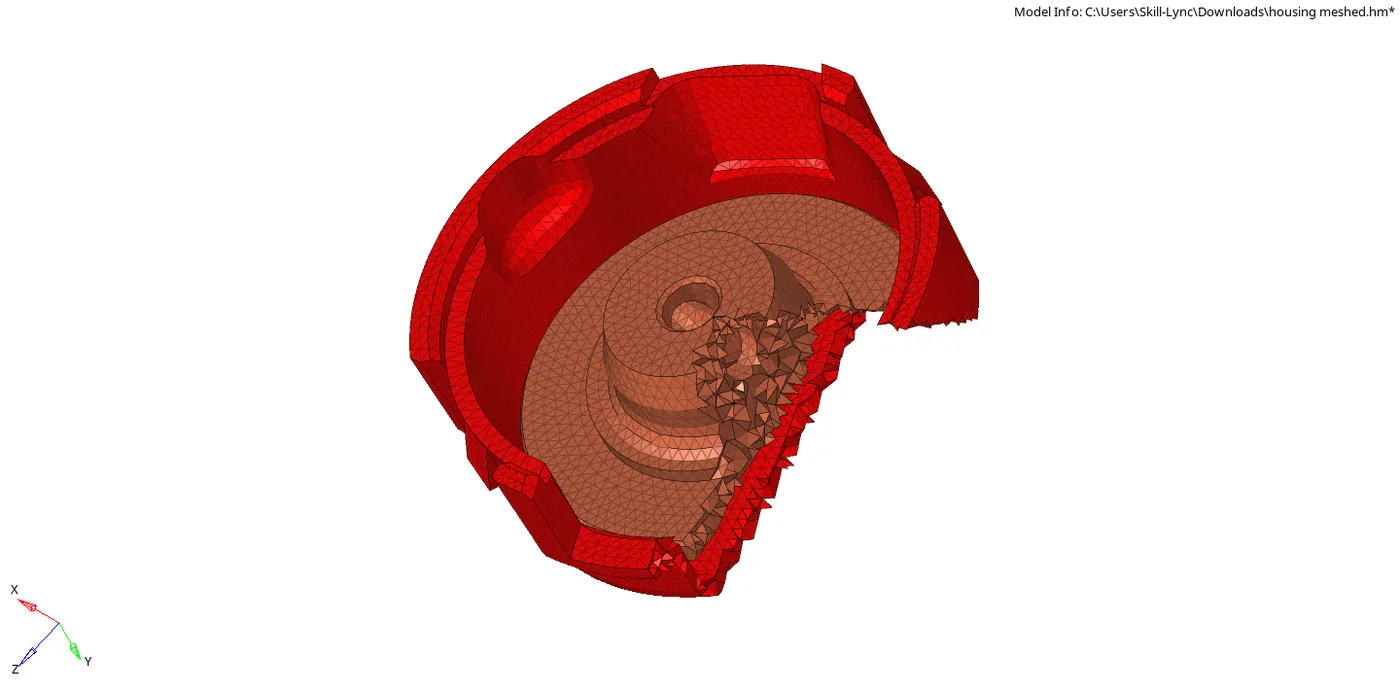
Procedure:
For arm bracket model :
1.The given arm bracket model is imported into Hyperworks, It has four parts namely base, arm curve, arm straight and boss.
2.The whole model is checked for geometrical errors after which separate meshing option is used for meshing all the four components of the model which is as follows
a). Base: First only the base is selected to be made visual and all other components are hidden.then the base is selected to "Make current".2D mesh is done on one surface of the base after which solid mesh is done by Element offset option which is available in the 3D panel.
b). Arm curve: now the arm curve part is made to be visible along with the 2D mesh which is created on the base all other parts are made to be hidden. then the arm curve is selected to be "Make current". The Spin option which is available in the 3D panel is used to generate the mesh along the curved surface of the part.
c). Arm straight: now the arm straight part is made visible along with the 2D mesh for the arm curve which is created from the Faces option. then the arm straight is selected to be "Make current". The linear solid option which is available in the 3D panel is used to generate the mesh.
d). Boss: now the boss is made visible along with the meshed arm straight, then the boss is selected to be "Make current". The Solid map option which is available in the 3D panel is used.
3.The 2D mesh which is created along the process needed to be deleted using F2(Keyboard shortcut for delete)
F2`rarr`elements`rarr`by config `rarr`hex8 `rarr`select entities `rarr`delete entities.
4.Mask option F5(Keyboard shortcut) is used to check whether the components have properly meshed.
Fig 6: Given model of arm bracket.
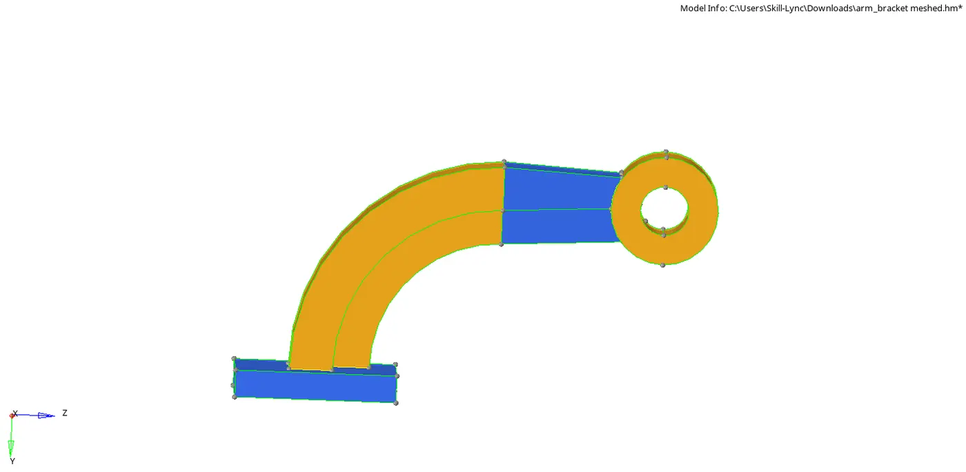
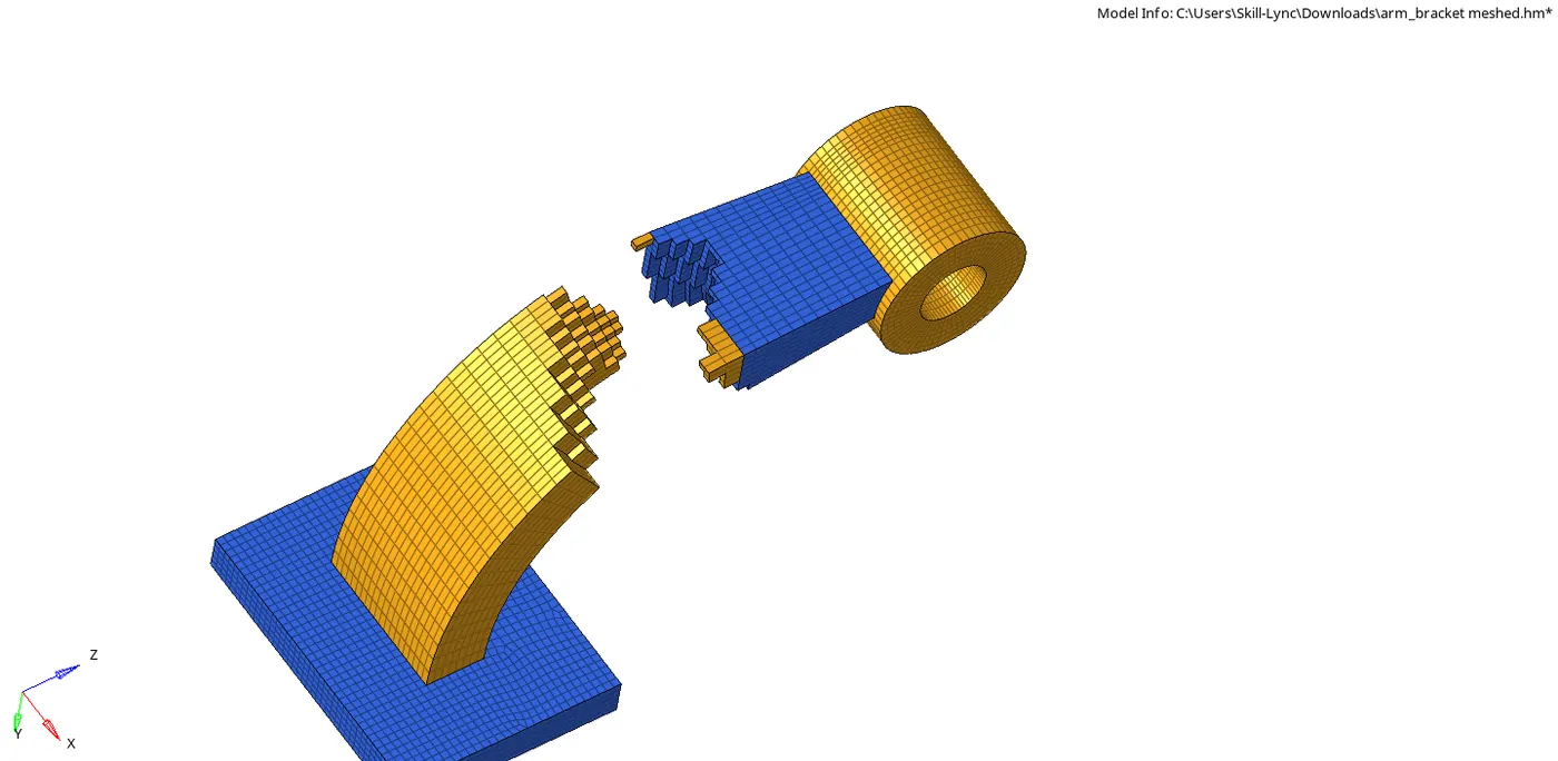
Fig 7: Meshed model of arm bracket.
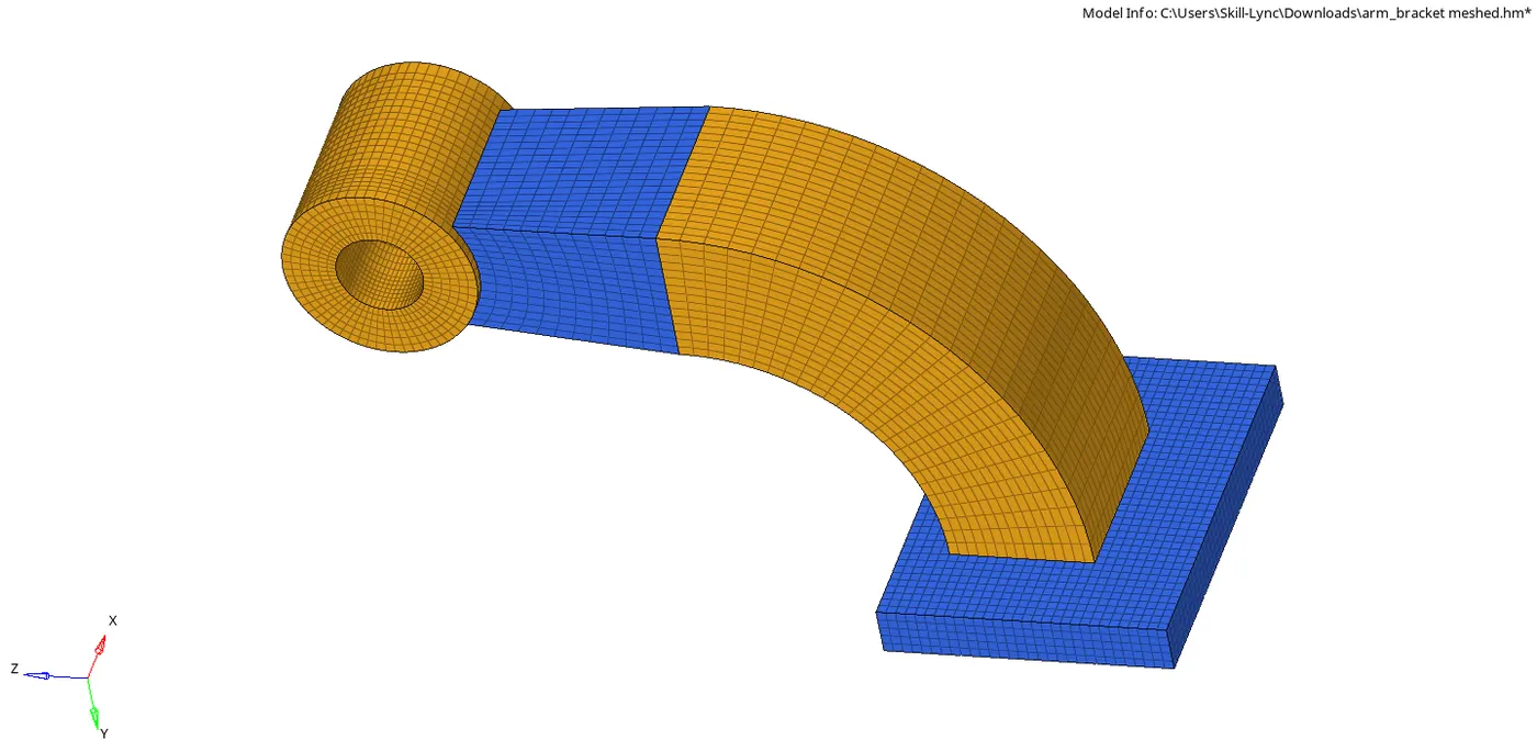
Fig 8: Masked model of the 3D meshed components.
Conclusion:
1.Tetra and hexa meshing of the given two components is done using different options available in the 2D and 3D panel, with the quality parameters being cleared with proper mesh flow achieved.
2.RADIOSS file is imported into the HyperWorks with run time and frequency being edited to create a h3d file for animation which is viewed in hyperview.