Week 9-Challenge
AIM: Connection representation of frame assembly
Objective:To mesh the frame assembly and make connection representation of specific parts.
Connections:
A. Right_Rail_2 & Front_truss_1:- Seam-Quad(angled+capped+L)
B. Left_Rail_2 & Front_truss_1:- Quad elements
C. Front_truss_2, Front_truss_1 & Right_Rail_1:- Spot weld with 3 Layers and 5 mm Diameter
D. Front_truss_2, Front_truss_1 & Left_Rail_1:- Hexa (Adhesive)
E. Rear_truss_2 & Right_Rail_2:- Bolt Connector
F. Rear_truss_2 & Left_Rail_2:- Bolt Connector
G. Right_Rail_1 & Right_Rail_2:- Spot-weld with Rigid Elements
H. Left_Rail_1 & Left_Rail_2:- Spot-weld with Spring Elements
I. Rest all the component left Join them with suitable connectors.
PROCEDURE:
1. Import the CAD model under optistruct profile.
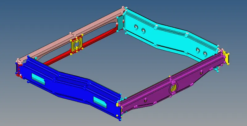
FIG 1: Given frame assembly model.
2. Meshing the model with 2D shell elements
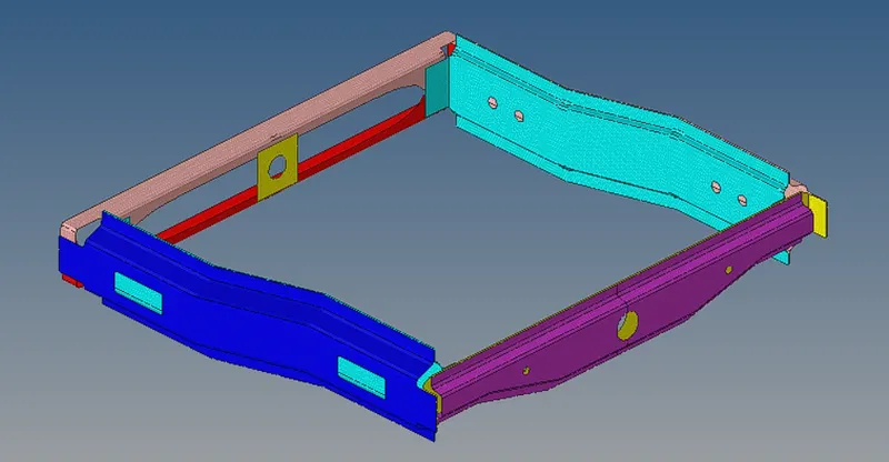
Target element length- 5mm
FIG 2: Meshed Frame assembly.
3. Connections:
A. seam weld connection- Hide all the connections except Right_Rail_2 & Front_truss_1 (2D>connectors>seam type as Seam-Quad(angled+capped+L).
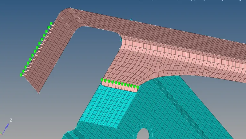
FIG 3-Right_Rail_2 & Front_truss_1- Seam-Quad(angled+capped+L)
B. Quads - hide all the components except Left_Rail_2 & Front_truss_1 (2D>connectors>seam type as Quad elements).
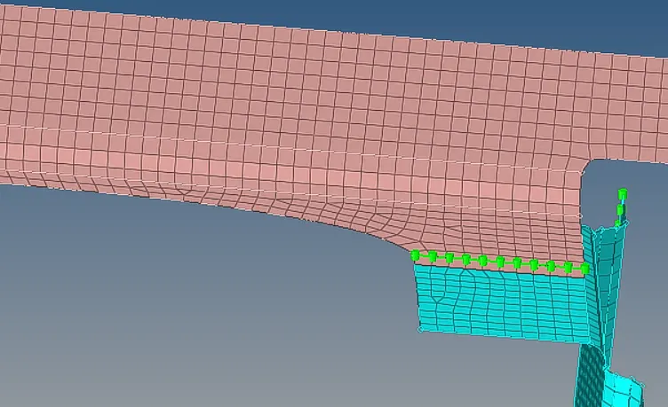
FIG 4: Left_Rail_2 & Front_truss_1- Quad elements
C. Spot weld with 3 Layers and 5 mm Diameter -
Hide all the components except Front_truss_2, Front_truss_1 & Right_Rail_1.
2D> CONNECTORS> SPOTWELD num of layers 3.
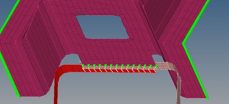
FIG 5- Front_truss_2, Front_truss_1 & Right_Rail_1- Spot weld with 3 Layers and 5 mm Diameter.
D. Hexa adhesive
Hide all the comonents except Front_truss_2, Front_truss_1 & Left_Rail_1 ( 2D> CONNECTORS> seam type as Hexa (Adhesive).
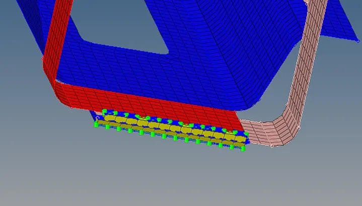
FIG 6- Front_truss_2, Front_truss_1 & Left_Rail_1- Hexa (Adhesive).
E. Bolt Connector
Hide all the components except Rear_truss_2 & Right_Rail_2 (2D> CONNECTORS> Bolt).
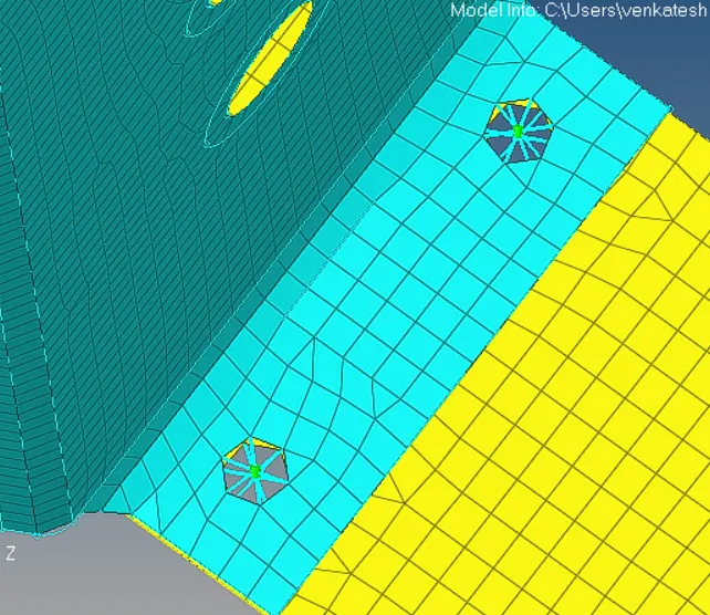
FIG 7- Rear_truss_2 & Right_Rail_2- Bolt Connector.
F. Hide all the components except Rear_truss_2 & Left_Rail_2 (2D> CONNECTORS> Bolt).
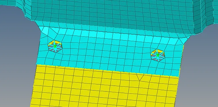
FIG 8- Rear_truss_2 & left_Rail_2- Bolt Connector.
G. Spot weld
Hide all the components except Right_Rail_1 & Right_Rail_2(2D> CONNECTORS> spot weld type rigids).
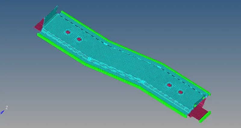
FIG 9- Right_Rail_1 & Right_Rail_2- Spot-weld with Rigid Elements.
H. Hide all the components except Left_Rail_1 & Left_Rail_2 (2D> CONNECTORS> spot weld type springs).
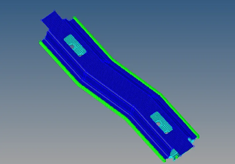
FIG 10- Left_Rail_1 & Left_Rail_2- Spot-weld with Spring Elements.
I. Remaining components are connected with seam, springs, bolts.
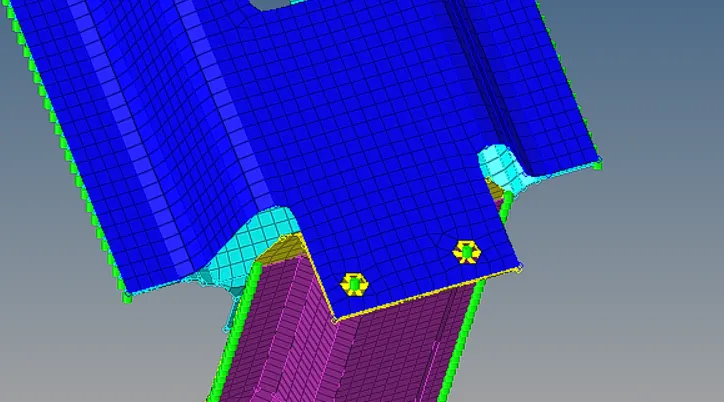
FIG- Bolt.
CONCLUSION:
- Frame assembly meshed with element size of 5mm.
- connectors are created with given parameter section.
- Rest of components are connected with seam, spots, bolts.
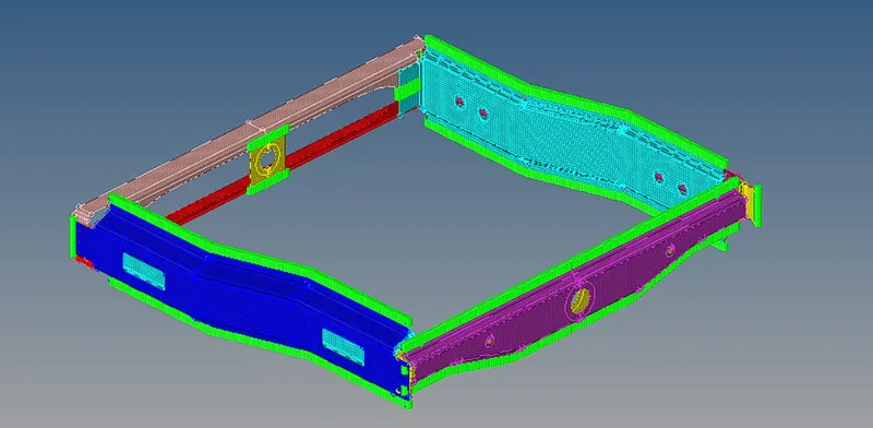
FIG- Final connected model.