Week 6- Challenge
AIM: To mesh the CAD model with given quality criteria and assigning the thickness.
Objectives:
- Extracting the mid surface.
- Meshing on the mid surface( 2D shell mesh) following the quality criteria.
- Assigning the thickness to the cad model.
CAD Model:
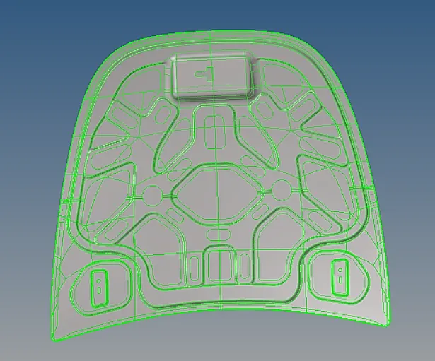
FIG- HOOD
This CAD model has 4 parts.
Inner extract, Outer extract, Hinge and Latch.
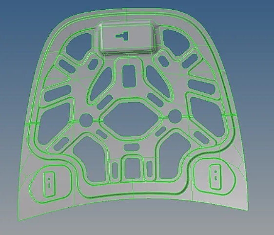
The above fig shows the inner extract of the CAD model.
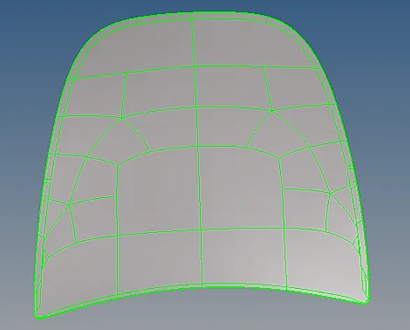
The above fig shows the outer extract of the CAD model.
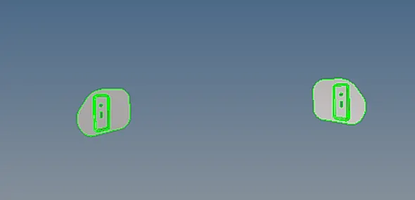
The above fig shows the hinge of the CAD model.
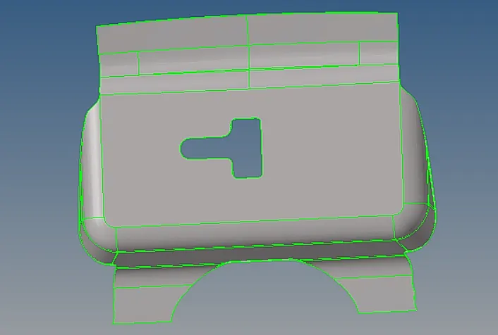
The above fig shows the latch of the CAD model.
Procedure:
1) Extracting the mid surface
Extracting the mid surface for each component seperately
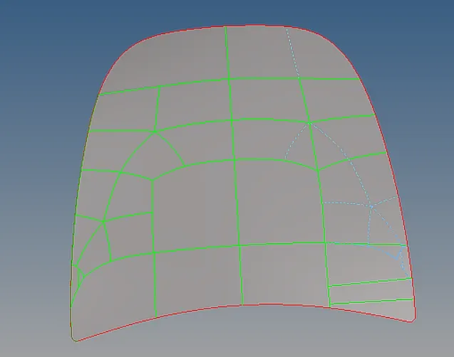
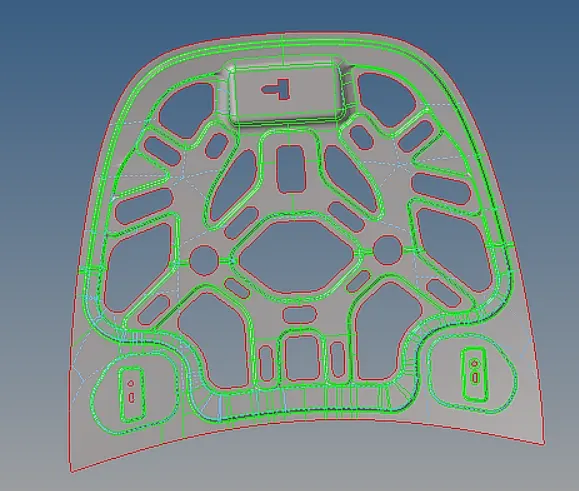
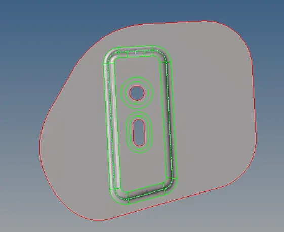
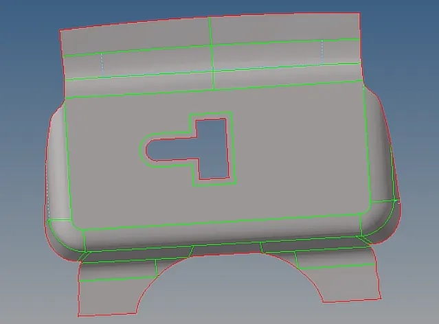
The above fig shows the mid surface of outer extract, inner extract, hinge and latch in order.
Geom > midsurface > auto extraction > extract.
2) Meshing
- Spend sufficient time in studying the geometry
Common observation in CAE engineers start meshing immediately¸ without properly studying the geometry and paying minute attentions to all the requirements and instructions provided. Observing the geometry several times and thinking from all the directions is strongly suggested. Mental visualization of the steps or planning before starting the job is first step in right direction i.e. good meshing.
- Time estimation
Nowadays trend is towards client or boss specifying time estimation for a given job to service provider or subordinate. Sometimes it is decided on mutual understanding. Time estimation is very relative and one can find lot of difference in estimation by different engineers.
Usually a less experienced person will estimate more time also if someone is handling the job for first time then also he will require more time. If similar kind of jobs are given to same engineer again and again, meshing time would reduce drastically.
- Geometry check
Generally, CAD data is provided in. igs format. Whatever software people might claim but the ground reality is “geometrical cleanup is an integral part of meshing activity’’. CAE engineer should have at least basic knowledge of CAD. Before starting the job, geometry should be carefully checked for
- Free edges
- scar lines
- Duplicate surfaces
- small fillets
- small holes
- beads
- Intersection of parts
If suppressing fillets, small holes, beads, generation of mid surfaces etc. is required for meshing then why not CAD data is provided like what is needed for CAE by the CAD engineers? Yes, theoretically it would be an ideal solution but practically every one work with very tight schedules and target dates. CAD data is generated keeping in mind final drawing to be released for manufacturing. The same drawing is provided simultaneously to tools and Fixture manufacturing, vendors, purchase engineers and CAE engineers etc.
- Symmetry check
Meshing only partial part and reflecting it is advisable, sub part symmetry repetition of features and possibility of copy paste command meshing highlighted 22.5-degree portion and then reflection and rotation would lead to fast meshing and as well as same structure of elements and nodes around critical areas(holes).
- Selection of type of elements
In real life rarely, we use one type of element, its usually combination of different types of element’s. i.e. 1-d, 2-d, 3-d and others.
- Type of meshing : Geometry based mesh is associated to geometry. If geometry is modified mesh will also get updated accordingly. here we meshed the model with 2D shell mesh.
Critical areas are high stress locations. Dense meshing and structured mesh (no tria’s/Penta’s) are recommended in these regions. Areas away from critical are general areas. Geometry simplification and coarse mesh in general areas are recommended (to reduce total DOFs and solution time).
3) Quality Criteria
|
Sr. No |
Quality criteria |
Target Element Size = 5 |
|
1 |
Minimum Element Length |
2 |
|
2 |
Maximum Element Length |
8 |
|
3 |
Warpage |
15 |
|
4 |
Jacobian |
0.6 |
|
5 |
Minimum Quad Angle |
45 |
|
6 |
Maximum Quad angle |
135 |
|
7 |
Minimum Tria angle |
20 |
|
8 |
Maximum Tria angle |
120 |
|
9 |
Aspect Ratio |
5 |
|
10 |
Skew angle |
45 |
|
11 |
Percentage of Tria |
10% |
If the meshed model not satisfying the quality criteria, use clean up tools or remesh those regions untill satisfying the above given quality criteria.
To find edges- Tools > edges > find edges
To find normals- Tools > normals > display.
To find penetrations- Tools > penetrations > Find.
To optimize elements- 2D > quality index > clean up tools > element optimization/ split/ combine / create/drag tria/node optimization.
To reflect the elements- Tools > reflect > select the elememnts > reflect.
To pre view equivalance and adjust the equivalance- Tools > edges > preview equivalance > equivalance.
Result: The CAD model is meshed with required quality criteria.
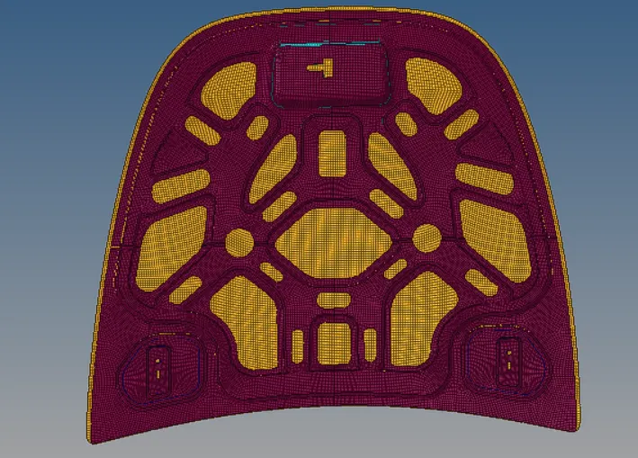
The above fig shows the meshed CAD model following the quality criteria.