Week 9-Challenge
| Right_Rail_2 & Front_truss_1 | Seam-Quad(angled+capped+L) |
| Left_Rail_2 & Front_truss_1 | Quad elements |
| Front_truss_2, Front_truss_1 & Right_Rail_1 | Spot weld with 3 Layers and 5 mm Diameter |
| Front_truss_2, Front_truss_1 & Left_Rail_1 | Hexa (Adhesive) |
| Rear_truss_2 & Right_Rail_2 | Bolt Connector |
| Rear_truss_2 & Left_Rail_2 |
Bolt Connector |
| Right_Rail_1 & Right_Rail_2 |
Spot-weld with Rigid Elements |
| Left_Rail_1 & Left_Rail_2: | Spot-weld with Spring Elements |
|
Rest all the component left Join them with suitable connectors |
objective- to create connectors to the components of the given model as per mentioned table
1.mesh the given component and use the element size as 6
a. 2d--> automesh-->surface-->quads-->element size 6--> create
2.check for quality criteria and try remeshing again or use clean up to over come failed elements
3.add the material and property for the components
in the left side of corner below components hit on the right mouse button and create material and assign property to it with thickness
A.Right_Rail_2 & Front_truss_1 Seam-Quad(angled+capped+L)
go to 2D and click on connectors-->seam--> select noddes for seam weld and component
-->assign spacing as 5--> component type-->seam quad (angled+clapped+l)
and remesh the distorted elemsnts
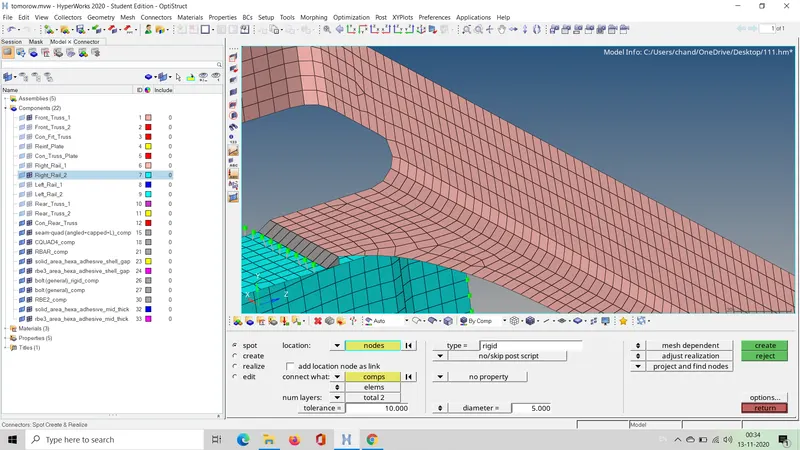
B.Left_Rail_2 & Front_truss_1(QUAD ELEMENTS)
2D-->connectors --> seam-->select nodes for seam welding--> select components-->spacing --> 5--> component type--> quad--> imprint--> hit create
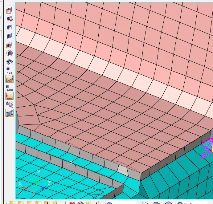
C.Front_truss_2, Front_truss_1 & Right_Rail_1:- Spot weld with 3 Layers and 5 mm Diameter
Go to 1D --> connectors->spot--> select nodes for spot weld -->select component--> layer3-->type weld-->diameter 5 --> create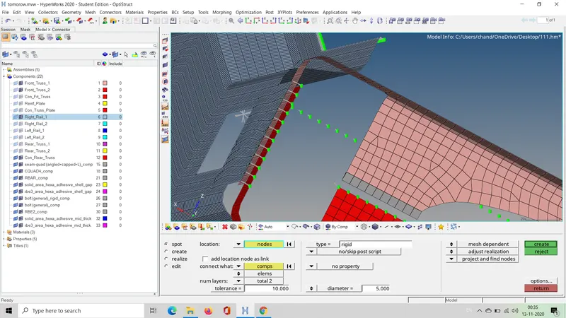
D.Front_truss_2, Front_truss_1 & Left_Rail_1:- Hexa (Adhesive)
go to 2D --> connectors-->area-->select element for adhedsive--> component--> type adhesive-->create
remesh the distorted mesh
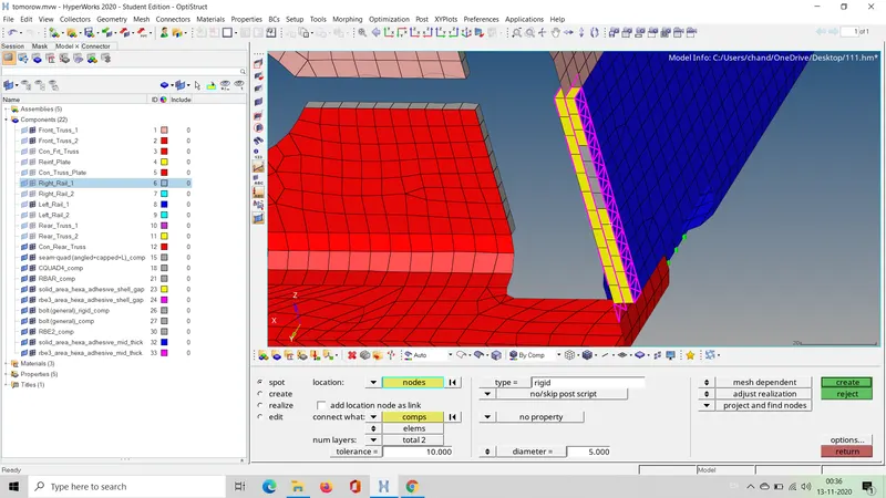
E. Rear_truss_2 & Right_Rail_2:- Bolt Connector
Go to 2D--> connectors--> bolt --> select nodes-->component--> type-->bolt general--> select create hole if none,--> create
remesh the distorted elements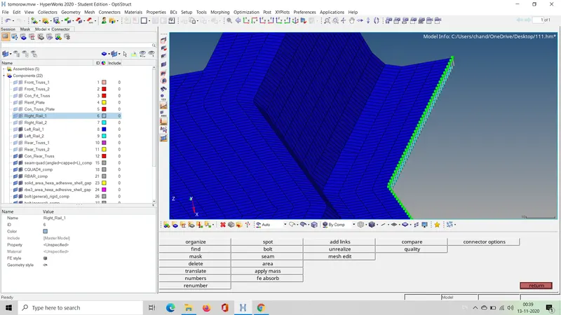
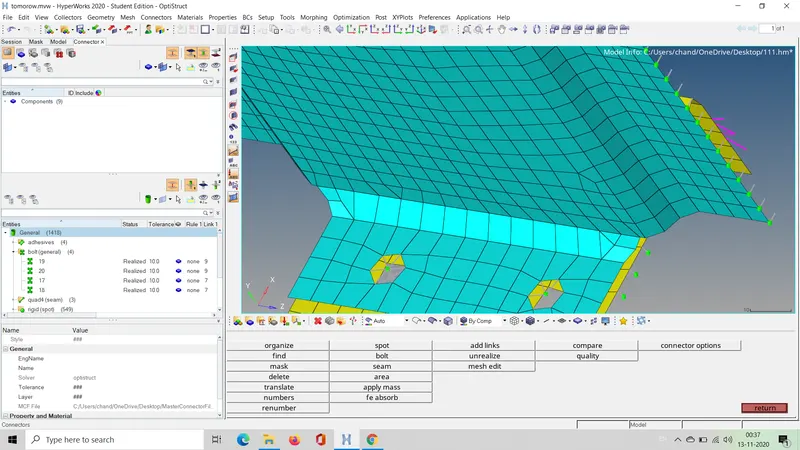
F.Rear_truss_2 & Left_Rail_2:- Bolt Connector
Go to 2D--> connectors--> bolt --> select nodes-->component--> type-->bolt general--> select create hole if none,--> create
remesh the distorted elements
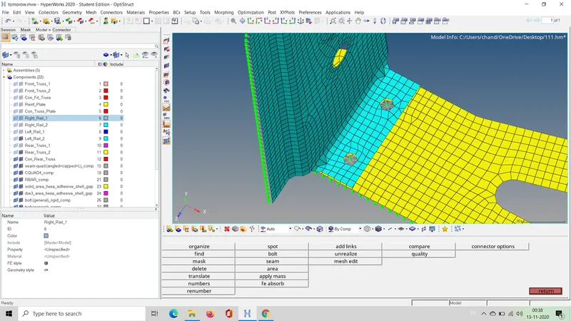
G.Right_Rail_1 & Right_Rail_2:- Spot-weld with Rigid Elements
Go to 1D--> connectors--> spot --> select nodes for creating spot weld--> select components-->layer 2--> type rigid-->diameter as 5 --> create
remesh the distorted elements
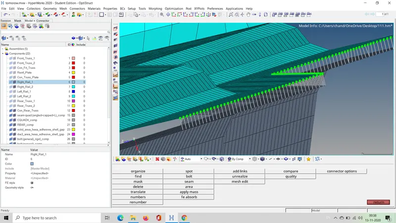
H.Left_Rail_1 & Left_Rail_2:- Spot-weld with Spring Elements
Go to 1D-> connectors--> spot--> select nodes for spot weld
--> select components-->layer 2--> type rigid-->diameter as 5 --> create
remesh the distorted elements
I. do same with the remaining component too
RESULT AND CONCLUSION
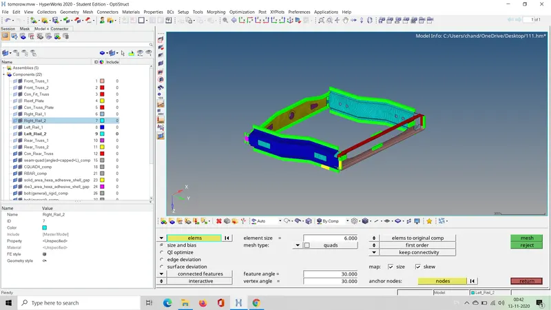
connectors have been assigned to the respective components as per the requirement and below is the image of final frame assembly with connectors
THANK YOU