Week 9 - Challenge 1 - Base Bracket Design
BASE BRACKET DESIGN USING CATIA V5
OBJECTIVE: - Create the Base Bracket Plastic component through the given Class-A surface. To begin with, the tooling axis for the given Class-A Surface should be created meeting the requirements of the draft angle and at the end perform the Draft analysis on the model.
INTRODUCTION: - The plastic component used for light weight and for good strength. Plastic parts have various applications in Automotive industries, Home appliances, Electronic equipment. We need to deal with various designing considerations during plastic part design.
During this exercise, I have learned various commands in the module “Wireframe and Surface Design” of CATIA V5. These commands are :-
- Surface Group - Extrude, Revolve, Offset, Sweep, Fill, Multi-section surface, Blend.
- Operation Group - Join, Untrim, Split, Trim, Boundary, Extract, Translate, Extrapolate.
DESCRIPTION: - We used various terminologies during the design of the plastic component “Base Bracket” in CATIA V5.
1. CLASS-A Surface
2. CLASS-B & CLASS-C Surface
3. Tooling Axis
4. Draft Analysis
- CLASS-A Surface: - A Class-A surface is any high-quality plastic component that you see, touch, or engage with inside or outside of a vehicle. Aesthetics play a significant role in injection moulded parts being classified as a “Class-A” surface. A surface means visible surface.it will give a styler.
- CLASS-B & CLASS-C Surface: - B surface means thickness of a part it is not visible it is inside part. c surface means A and B combined to give C surface.
- Tooling Axis: - The direction in which the mould or core and cavity opens is the tooling axis.
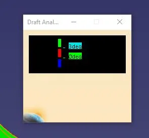
- Draft Analysis: - The Draft Analysis allows the user to easily analyse a part for proper draft angle. A Draft Angle describes the amount of taper for moulded or cast parts perpendicular to the parting line.
DESIGN METHODOLOGY AND APPROACH: - I have followed a structured approach to design a plastic component “Base Bracket” which are mentioned below:
When designing a plastic component, A Design engineer gets an input in the form of Class-A surface which was prepared by the Industrial Designer.
- INPUT: - We need to input geometrical set. A) Class A Surface, B) Tooling Axis
1. Insert Class A surface.
2. Find out the best possible tooling direction which will be cost effective using tooling axis analysis method.
CLASS A SURFACE
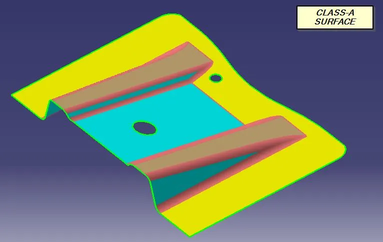
Tooling axis analysis approach:
1. Find the part clearing direction in tool X, Y and Z then create a dummy tooling axis parallel to tooling direction.
2. Create intersect sketch using X-plane & surface then create verify part clear from tooling for surfaces which are at angle to the tooling direction by creating lines using points of the angular lines.
3. Create bisect lines using these lines and point which should be same as dummy tooling axis which means parts surfaces get clear from tooling.
4. Above approach 2 & 3 do the same for the Y direction also.
5. Do the draft analysis. Take feature draft analysis from analysis group present in insert option. Use compass option in direction group and place it on tooling axis then select any face.
6. B-Surface creation. Extract the A surfaces and untrim them. Offset the boundaries of the surfaces using extrapolate command and trim all the surface to achieve desired shape.
7. Offset it at desired thickness to get the output rib surface.
8. Create base surface by offset A surfaces and untrim them then offset boundaries by extrapolate and trim the surfaces to get the final B surface.
9. Create C surface by taken boundary of A surface and sweep the boundary along the tooling direction then select the draft direction to form the C surface.
10. At the end do the final trim of A surface, B surface and C surface by join command to achieve a closed body.
11. Create a solid body of the closed surface using close surface command in part modelling.
Draft analysis color variation scale
Feature Draft Analysis with Class A Surface
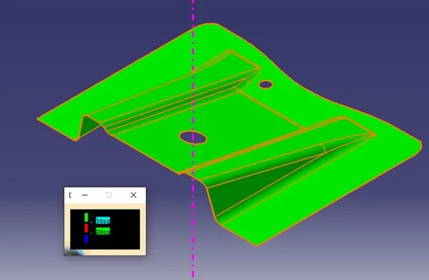
Feature Draft Analysis with solid body
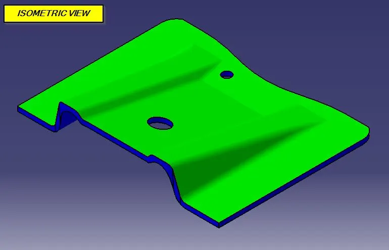
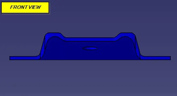
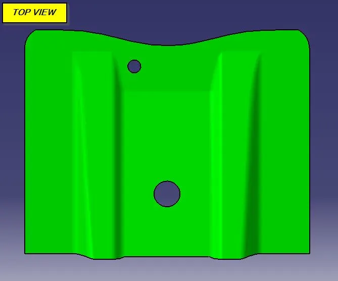
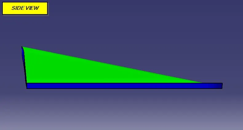
Closed Surface
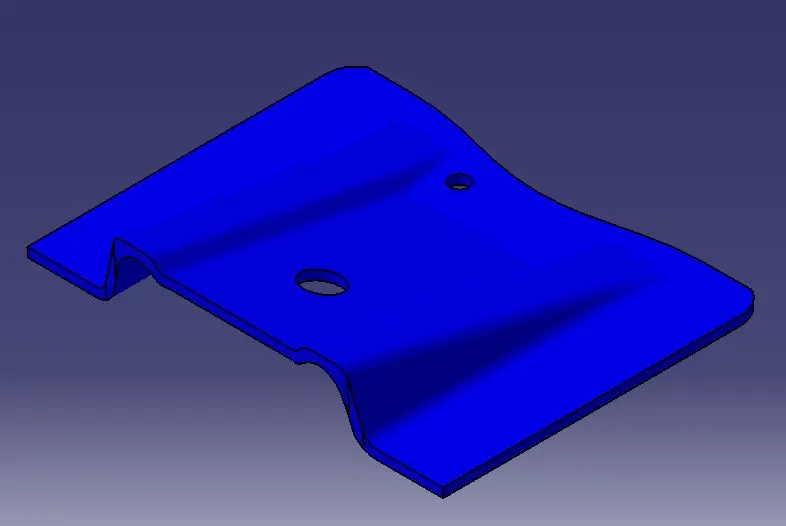
CONCLUSION: Create base bracket following plastic part design guidelines. Developed Class B & C surfaces using trim, join, boundary and extrapolate commands.