Photo Realistic Rendering
MODELLING & RENDERING OF AMERICAN CHOPPER USING SOLIDWORKS
- INTRODUCTION: - American chopper is a special type of stylish bike. Doing CAD modelling using Solidworks 2019. Nowadays Solidworks is extensively used in mechanical and automotive industries because it has lots of modules which are very useful, and its user interface is very simple and easy to use.
- OBJECTIVE: - Aim of the course is to CAD modelling and rendering of an American chopper using Solidworks software. After this course, learn many modules of Solidworks like solid modelling, surface modelling, assembly modules using different types of mates. Create individual chopper component and their assemblies and done rendering on American chopper.
- DESIGN METHODOLOGY/APPROACH: -
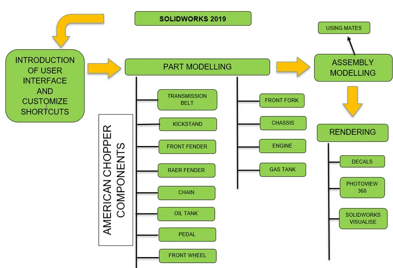
- DETAILED DESCRIPTION OF PROJECT: - Modelling and rendering of American chopper bike using Solidworks 2019. The approaches of modelling American chopper are: -
- Firstly, customize the shortcuts in Solidworks for easy and fast CAD modelling.
- Part modelling of individual American chopper components using sketching and solid & surfacing commands.
- After part modelling assemble the individual components using many types of different mates in assembly module.
- Modifications in individual components in an assembly workplace.
- After completing assembly of American chopper give a realistic view of model using rendering module with PhotoView 360.
- Customize the shortcuts in Solidworks for running faster and actives commands easily during modelling. You can go in setting and select customize option where you can modify the shortcuts menus. You can see many shortcut options in settings and customize these shortcuts as per your needs and save modelling time.
- After customization of shortcuts menu, we will start Part modelling of individual components of American chopper. Before start modelling of individual parts, firstly create templates which use during modelling when we create new part file.
PART MODELLING OF AMERICAN CHOPPER COMPONENTS
1. TRANSMISSION BELT: - A belt is a loop of flexible material used to link two or more rotating shafts mechanically, most often parallel. Belts may be used as a source of motion, to transmit power efficiently or to track relative movement. Belts are looped over pulleys and may have a twist between the pulleys, and the shafts need not be parallel.
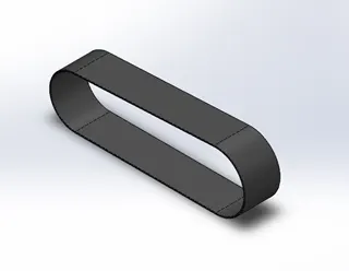
Image - Transmission Belt
- FEATURES USED TO CREATE TRANSMISSION BELT
- Sketch
- Line
- Offset Entities
- Extrude Boss/Base
- Fillet
- Appearance
- SKETCH: - Sketch is a Two-Dimensional geometry (lines, Circles, Arc, ellipse) representation which use to convert 2D object into 3D.
- OFFSET: - offset one or more sketch entities, selected model edges, or model faces by a specified distance. For example, you can offset sketch entities such as splines or arcs, sets of model edges, loops, and so on.
- EXTRUDE BOSS/BASE: - An Extruded Boss/Base feature will allow you to take a 2D sketch and add thickness to it in the third dimension.
- FILLET: - Fillet is widely used command which can rounded the faces or edges of a part. You can fillet all edges of a face, selected sets of faces, selected edges, or edge loops.
- APPERANCE: - An appearance defines the visual properties of a model, including color and texture. Appearances do not affect physical properties, which are defined by materials.
PROCEDURE OF MODELLING
- Create new part file using created template.
- Select front plane and start sketching choosing line tool.
- Make lines & arc and do the dimensioning as given for fully defining sketch.
- Select offset tool and choose a line and give offset dimension.
- Choose Extrude Boss/Base feature from solid modelling group and give dimensions with blind offset.
- Apply fillet as given dimensions using fillet feature from solid modelling group.
- Add appearance (matte rubber) from appearance library.
- Save the part model and give name “Transmission Belt”.
Note: - Use esc key for exiting from any commands.
2. KICKSTAND: - A kickstand is a device on a bicycle or motorcycle that allows the bike to be kept upright without leaning against another object or the aid of a person. A kickstand is usually a piece of metal that flips down from the frame and contacts to the ground.
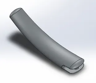
Image - Kickstand
- FEATURE USED TO CREATE KICKSTAND
- Sketch
- Ellipse
- Spline
- Lofted Boss/Base
- Extrude cut
- Dome
- Fillet
- Appearance
- SPLINE: - You can use B-splines to create complex curves. You can define and modify them using several controls, including spline points, spline handles, and control polygons. A single B-spline can have multiple through points and spans (the region between through points). You can apply curvature constraints at each endpoint. At each through point, you can weigh the tangency vector and control the tangency direction.
- LOFTED BOSS/BASE: - Loft creates a feature by making transitions between profiles. You create a loft using two or more profiles. Only the first, last, or first and last profiles can be points. All sketch entities, including guide curves and profiles, can be contained in a single 3D sketch.
- EXTRUDE CUT: - Extrude cut feature is use for removing the material from any part model.
- DOME: - The software calculates the distance using the radius of the arc as a basis for the dome. It creates a dome that is tangent to the adjacent cylindrical or conical face.
PROCEDURE OF MODELLING KICKSTAND
- Create a new part using template.
- Select front plane and draw an ellipse and give dimensioning.
- Select mid plane and draw a spline and give smart dimensioning for fully defining sketch
- Select plane feature and choose spline and end of spline to create a plane-1.
- Create a 2nd ellipse on plane-1 and give smart dimensioning values for fully defining ellipse.
- Select spline and 2nd ellipse center point and make coincide using pierce option.
- Select lofted boss/base from solid modelling group and choose both ellipse and splines (for center path) for make a solid lofted part.
- Choose dome feature from solid modelling group and select both sides face of lofted part for making a dome shape and enter dimension value as given.
- Make a mid-point rectangle on mid-plane and give some dimension values.
- Remove material using extrude cut feature by both-through all option.
- Draw a line of some length using smart dimensioning on plane-1 and select split feature from solid modelling group and cut the material of one side of given line.
- Draw a circle on top-plane at given dimension and add material using extrude boss/base with up to next option.
- Apply fillets of some radius as given on edge by choosing internal and external faces.
- Add appearance on model from appearance library “Chrome material”.
- At the end save the model and give name “Kickstand”.
3. FRONT FENDER: - Fender is the American English term for the part of an automobile, motorcycle or other vehicle body that frames a wheel well (the fender underside). Its primary purpose is to prevent sand, mud, rocks, liquids, and other road spray from being thrown into the air by the rotating tire. Front fender mounted on chassis front side above the front wheel.
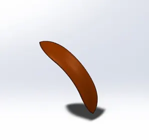
Image - Front Fender
- FEATURE USED TO CREATE FRONT FENDER
- Sketch
- Offset Entities
- Trim Entities
- Revolve
- Dynamic Mirror
- Split
- Appearances
- TRIM ENITITIES: - You can use Power trim to trim multiple, adjacent sketch entities by dragging the pointer across each sketch entity.
- REVOLVE: - Revolves add or remove material by revolving one or more profiles around a centerline. You can create revolved boss/bases, revolved cuts, or revolved surfaces. The revolve feature can be a solid, a thin feature, or a surface.
- DYNAMIC MIRROR: - Dynamic Mirror Entitiesused to be more limited in the past as user was only allowed to use this tool with a centerline as the mirror line.
- SPLIT: - Split tool used for cutting a body in to 2 separate body.
PROCEDURE OF MODELLING FRONT FENDER
- Create a new part file using templates and rename planes.
- Draw a 3-point arc on vertical plane front fender and give smart dimensioning values & relations as mentioned.
- Offset arc 6mm using offset entities tool.
- Select axis feature and make an axis choosing 2-planes.
- Select revolve feature from solid modelling group and choose axis & sketch which revolved around an axis by given angle value as given.
- Add appearance from appearance library “Siena paint”.
- Draw a construction line on top plane front fender and choose dynamic mirror feature.
- Draw a spline at one side of construction line and given dimensioning for fully defining sketch.
- Select split tool and cut the outside profile of part.
- Select Vertical-plane front fender and rotate the part.
- Make a construction line and select dynamic mirror feature.
- Again, draw a spline and do the dimensioning for fully defining sketch.
- Use split feature and cut the outer bodies.
- Apply fillet on edges.
- Save the part model using name “Front Fender”.
4. REAR FENDER: - Rear fender is mounted on chassis of the rear part above the rear wheel.
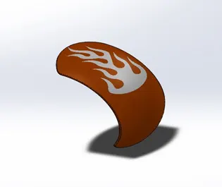
Image - Rear Fender
- FEATURE USED TO CREATE REAR FENDER
- Sketch
- Offset Entities
- Trim Entities
- Revolve
- Appearance
PROCEDURE OF MODELLING REAR FENDER
- Create a new part file using templates and rename planes.
- Draw a 3-point arc on vertical plane front fender and give smart dimensioning values & relations as mentioned.
- Offset arc 6mm using offset entities tool.
- Select revolve feature from solid modelling group and choose axis & sketch which revolved around an axis by given angle value as given.
- Draw a 3-point arc on center plane and given dimension values.
- Select split tool and cut the body side profile.
- Give some radius on edges using fillet feature.
- Apply appearance same as “Siena paint”.
- Save the model using name “Rear Fender”.
5. CHAIN: - Chain drive is a way of transmittin mechanical power from one place to another. It is often used to convey power to the wheels of a vehicle, particularly bicycle and motorcycle. Most often, the power is conveyed by a roller chain, known as the drive chain or transmission chain, passing over a sprocket gear, with the teeth of the gear meshing with the holes in the links of the chain.
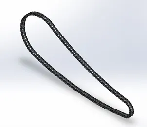
Image - Chain
- FEATURE USED TO CREATE CHAIN
- Sketch
- Trim
- Fillet
- Blocks
- Extrude Boss/Base
- Curve Driven Pattern
- Appearance
- CURVE DRIVEN PATTERN: - The Curve Driven Pattern tool allows you to create patterns along a planar or 3D curve. To define the pattern, you can use any sketch segment, or the edge of a face (solid or surface), that lies along the plane.
- BLOCK: - You can make a block from any single or combination of multiple sketch entities.
PROCEDURE FOR MODELLING CHAIN
- Create a new part file using templates and rename planes.
- Select plane and draw construction lines (horizontal and vertical).
- Draw 2-cirlces at end of construction lines and make tangent arcs using 3-point arc tool, after that given smart dimensioning for fully define sketch and trim extra lines.
- Draw sketch for creating block-1 using circle and 3-point arc tools.
- Draw sketch for creating block-2 using circle and slot tool and save both blocks as sketch file.
- Inset both blocks using block tool (tools—block--make block) and arrange on appropriate manner.
- Select extrude feature and add material using this blocks sketch profile.
- Select curve driven pattern feature from toolbar for making completely chain profile.
- At the end of chain profile make 2 chain rollers using manually sketching and extrude feature.
- Mirror all chain rollers for completing chain roller assemblies.
- Add appearance “Chrome plate”
- Save the part model using name “Chain”.
6. OIL TANK: - A fuel tank (also called a petrol tank or gas tank) is a safe container for flammable fluids. Though any storage tank for fuel may be so called, the term is typically applied to part of an engine system in which the fuel is stored and propelled (fuel pump) or released (pressurized gas) into an engine.
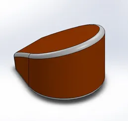
Image - Oil Tank
- FEATURE USED TO CREATE OIL TANK
- Sketch
- Extrude Boss/Base
- Combine
- Fillet
- Shell
- COMBINE: - In a multibody part, you can combine multiple bodies to create a single body.
- SHELL: - The shell feature is used to define the thickness of thin & thick shell element.
PROCEDURE FOR MODELLING OIL TANK
- Create a new part file using templates and rename planes.
- Sketching on top plane and draw sketch using lines and 3-point arc tool and add material using extrude boss/base feature at a given dimension.
- Select mid -plane and draw a sketch on it using line & spline tool and do smart dimensioning for fully define sketch.
- Add material using extrude boss/base feature and select both-through all option (De-select merge result).
- Select combine feature from solid modelling toolbar and choose common option and select both bodies.
- Apply fillet on edges and give radius value.
- Apply appearance “Siena paint”
- Select shell feature and choose body for make hollow section.
- Save the part using name “Oil Tank”.
7. PEDAL: - The pedal is the external part of bike which mount on chassis, is used to place the foot of rider for comfort during ride.
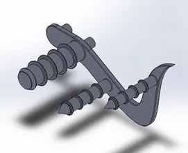
Image - Pedal
- FEATURE USED TO CREATE PEDAL
- Sketch
- Extrude
- Revolve
- Fillet
- Linear Pattern
- Dome
- Chamfer
- CHAMFER: - The chamfer tool creates a beveled feature on selected edges, faces, or a vertex.
- LINEAR PATTERN: - You can use linear patterns to create multiple instances of one or more features that you can space uniformly along one or two linear paths.
PROCEDURE FOR MODELLING PEDAL
- Select plane and draw fully defined sketch for extrude.
- Make leg rest by using revolve feature of fully defined sketched.
- Add chamfer and fillet at the end of leg rest and make dome at end face.
- Finally use linear pattern feature for patterning leg supports.
8. FRONT WHEEL: - Front wheel is a rotating part of bike which is connected to the front fork. A wheel is assembly of wheel rim, spider web, tire and hub. Rim is made of steel/alloy and tire which is attached on rim, made by rubber material.
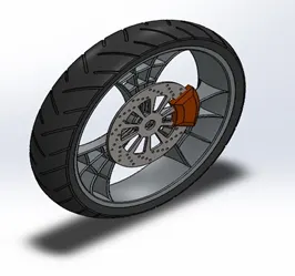
Image - Front Wheel
- FEATURE USED TO CREATE FRONT WHEEL
- Sketch
- Revolve
- Trim
- Fillet Sketch
- Boss Extrude
- Revolve Cut
- Linear Pattern
- Chamfer
- Cut Extrude
- Circular Pattern
- CIRCULAR PATTERN: - Use circular patterns to create multiple instances of one or more features that you can space uniformly around an axis.
PROCEDURE FOR MODELLING FRONT WHEEL
Front wheel is made by components which are: - Tire, Wheel Rim, Caliper & Rotor
- For Wheel Rim – The rim is made using Revolve Boss/Base feature by revolving fully defined sketch (at front plane) around an axis.
Make spider web by extrude boss/base feature using fully defined sketch according to dimensions and pattern the web using circular pattern feature.
- For Rotor – The rotor is extrude offset from midplane at given dimension and make holes on rotor using circular pattern feature.
- For Caliper – The caliper is made by extrude boss/base feature and after that making some chamfers and fillets on edges of caliper.
- For Tire – The tire is revolved around an axis by using of fully defined sketch which drawn as per dimensions. Make trades on tire by extrude cut and patterned them around tire using circular pattern feature.
9. REAR WHEEL: - Rear wheel is a rotating part of bike which is mounted back side of chassis. A wheel is assembly of wheel rim, spider web, tire and hub. Rim is made of steel/alloy and tire which is attached on rim, made by rubber material.
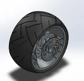
Image - Rear Wheel
- FEATURE USED TO CREATE REAR WHEEL
- Sketch
- Revolve
- Trim
- Sketch Fillet
- Extrude Boss/Base
- Planes
- Revolve Cut
- Linear Pattern
- Chamfer
- Fillet
- Extrude Cut
- Circular Pattern
PROCEDURE FOR MODELLING REAR WHEEL
Rear wheel is made by components which are: - Wheel Rim, Tire, Disc & Sprocket.
- For Wheel Rim – The rim is made using Revolve Boss/Base feature by revolving fully defined sketch (at front plane) around an axis.
Make spider web by extrude boss/base feature using fully defined sketch according to dimensions and pattern the web using circular pattern feature.
- For Tire – The tire is revolved around an axis by using of fully defined sketch which drawn as per dimensions. Make trades on tire by extrude cut and patterned them around tire using circular pattern feature.
- For Rotor – The rotor is extrude offset from midplane at given dimension and make holes on rotor using circular pattern feature.
- For Sprocket – The sprocket is made by extrude boss/base feature to offset from midplane at specified given dimension and cut some groove using extrude cut feature then patterned this cut using circular pattern feature.
10. FRONT FORK: - Front fork is the part of bike which use to hold the front wheel and work as a shock absorber. Mostly telescopic front fork used in bikes. A fork typically consists of two blades which are joined at the top by a fork crown.
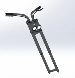
Image - Front Fork
- FEATURE USED TO CREATE FRONT FORK
- Sketch
- Extrude
- Trim
- Revolve
- Split
- Move/Copies Body
- Dome
- Mirror
- Combine
- Projected Curve
- Sweep
- MOVE/COPY BODY: - We can move and copy any surface/solid bodies using feature Move/Copy bodies.
- PROJECTED CURVE: - You can project a sketched curve onto a model face to create a 3D curve. You can also create a 3D curve that represents the intersection of two extruded surfaces generated by creating sketches on two intersecting planes.
PROCEDURE FOR MODELLING FRONT FORK
- Start with modelling of long barrel by revolving feature using sketched which draw on front plane.
- Make center part of fork where head light and speedometer mount which extruded and offset from some distance.
- Modelling of head light using revolve feature and after that move the head light at center using move/copy bodies feature.
- Add fillets at the end of head light for rounded corners.
- Mirror the crown using plane and mirror the whole left side body and complete the front fork modelling.
- Making handle using revolve boss/base feature for connect wiring.
- Draw 2 different sketched using 2 different planes for making composite curve by projected curve feature.
- Modelling of wire through sweep boss/base feature using composite curve and circle sketch.
11. CHASSIS: - Chassis is a skeleton part of bike which is made by round structural tubes. It is used as a main frame on which mount all other components like Engine, Gas tank, Pedal…each component.
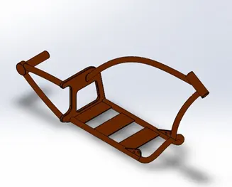
Image - Chassis
- FEATURE USED TO CREATE CHASSIS
- Sketch
- Convert Entities
- Offset
- Project Curve
- Trim
- Sweep
- Split
- Revolve
- Cut Extrude
- Fillet
- Combine
PROCEDURE FOR MODELLING CHASSIS
- Need reference from blueprint of chopper of making sketch for engine modelling.
- Drawn some sketch using chopper blueprint and create projected curves from sketches and sweep along with these projected curves for making round tubed chassis model.
- Make engine mounting bracket using extruded offset from plane and make holes on bracket for locate engine and mirror the engine mounting bracket.
- Make platform for engine placing using extrude boss/base feature.
- Make front fork supporting handle using revolve and combine feature.
12. ENGINE: - Engine is the power source for bike which covert heat energy into mechanical energy and propel the vehicle using this mechanical energy.
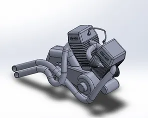
Image - Engine
- FEATURE USED TO CREATE ENGINE
- Sketch
- Trim
- Revolve
- Extrude Boss/Base
- Extrude Cut
- Offset
- Dome
- Fillet
- Projected Curve
- Composite Curve
- Sweep
- Mirror
- Circular Pattern
- Split
- COMPOSITE CURVE: - The Composite Curve tool combines all sketch entities into one continuous curve.
PROCEDURE FOR MODELLING ENGINE
- For engine modelling needed same chopper blueprint as we used before during chassis modelling.
- Firstly, make pulley by making sketch using blueprint and extrude, offset this sketch by reference of plane.
- Create a new plane for making engine block using extrude boss/base and cut engine fins by extrude cut feature and mirror it.
- Make air intake using projected curve and revolve & sweep feature.
- Finally make spark plug cable by composite curve to sweep feature.
13. GAS TANK: - Gas tank used to store the fuel which is required to making the power by engine combustion process.
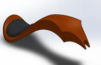
Image - Gas Tank
- FEATURE USED TO CREATE GAS TANK
- Trim
- Projected Curve
- Sweep Surface
- Lofted surface
- Fill Surface
- Surface Trim
- Surface Knit
- Sweep Cut
- Fillet
- LOFTED SURFACE: - Loft surface is used to make loft in between two profile along with guide path.
PROCEDURE FOR MODELLING GAS TANK
- In gas tank which is make a surface extrude along with blueprint by making sweep surface extrude making a tangential spline curve along with sweep path to make an outer tank wall.
- After that to make projected curve to extrude loft surface using guide curve.
- Make gas tank hollow using shell feature because gas tank is a Sheetmetal component.
ASSEMBLY MODELLING OF AMERICAN CHOPPER
Assembly modeling is a technology and method used by computer-aided design and product visualization computer software systems to handle multiple files that represent components within a product. The components within an assembly are represented as solid or surface models.
Assembly approach in computer aided design: -
- Bottom-Up assembly approach
- Top-Down assembly approach
- ASSEMBLY OF CHOPPER
Assembly of chopper is the process of joining the individual chopper components using constraints.
Types of Constraints: -
- Concentric
- Coincident
- Tangent with planes
- Parallel
- Perpendicular…..etc.
In Solidworks use mate option for doing any assembly.
There are 2 types mate used: -
- Mechanical Mates
- Advance Mates
PROCEDURE FOR ASSEMBLY OF AMERICAN CHOPPER
Call the chassis from the working directory and fix it. After that call individual component of chopper and make them constraint using matte option.
After completing assembly of American chopper please ensure the front wheel, rear wheel & Kickstand coincide with a common plane.
Images of Assembled American Chopper:
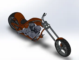
ISOMETRIC VIEW
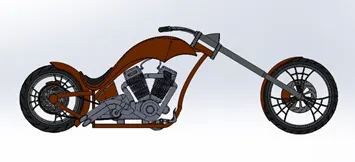
FRONT VIEW
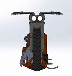
SIDE VIEW
RENDERING OF AMERICAN CHOPPER
Rendering or image synthesis is the process of generating a photorealistic or non-photorealistic image from a 2D or 3D model by means of a computer program.
Rendering has been in Solidworks two ways: -
- PhotoView 360
- Solidworks Visualize
- PhotoView 360: - PhotoView 360 is a SOLIDWORKS add-in that produces photo-realistic renderings of SOLIDWORKS models. The rendered image incorporates the appearances, lighting, scene, and decals included with the model.
In PhotoView 360 have some feature which are: -
- Environment Setting
- Light Setting
- Camera Setting
- Color and Material Editing
- Scene Composition
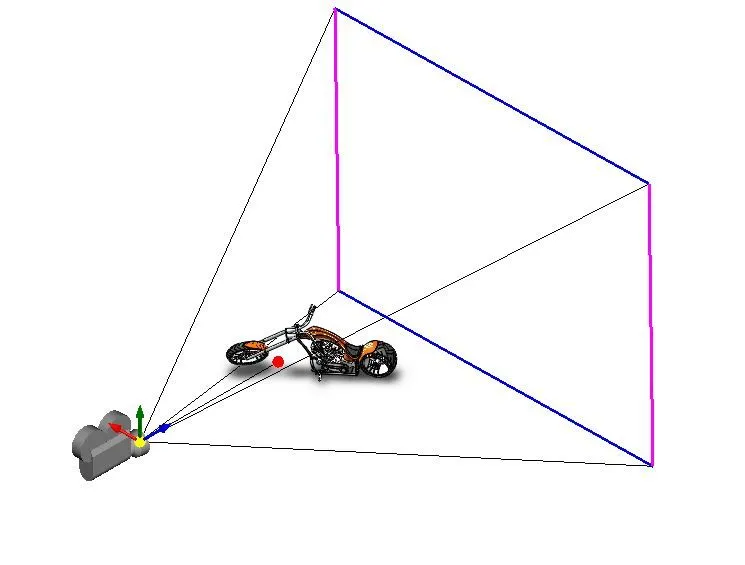
Camera Setting Snap
- SolidWorks Visualize: - SOLIDWORKS Visualize is a photo-realistic rendering tool that utilizes your CAD data to create magazine quality images or commercial quality animations.
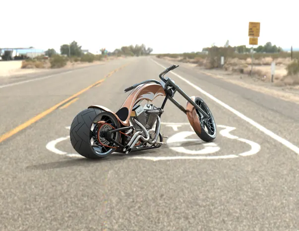
Rendering-1
Project Name- Rt66 Chopper
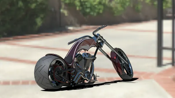
Rendering-2
Project Name- Driveway Chopper
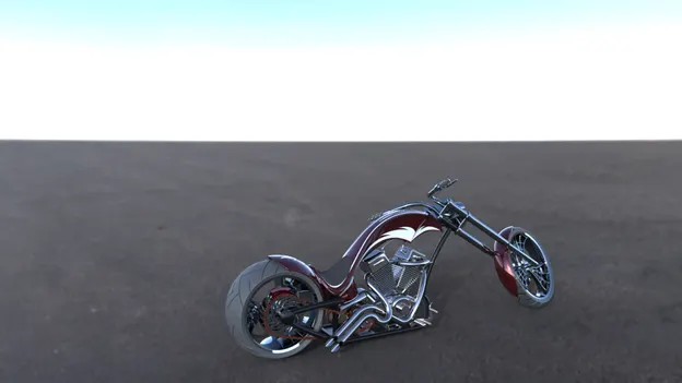
Rendering-3
Project Name- ITL Chopper
- CONCLUSION
- Knowledge of American chopper components modelled by converting sketch into solid model.
- Learn assembly of the all components using types of mate in assembly environment.
- The realistic image was rendered by use of PhotoView 360 and SolidWorks Visualize.