Radar Mast & Final Assembly of Yacht
- RADAR MAST
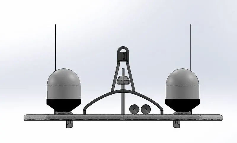
FRONT VIEW
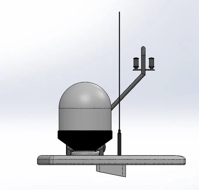
SIDE VIEW
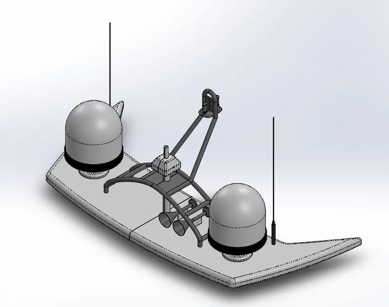
ISOMETRIC VIEW
FEATURE MANAGER TREE - 1
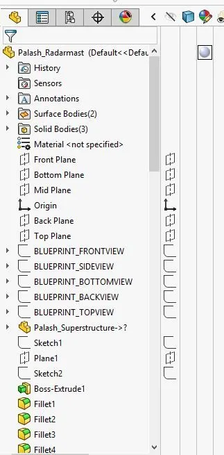
FEATURE MANAGER TREE - 2
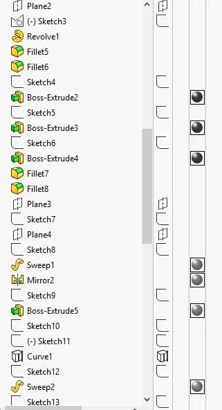
FEATURE MANAGER TREE - 3
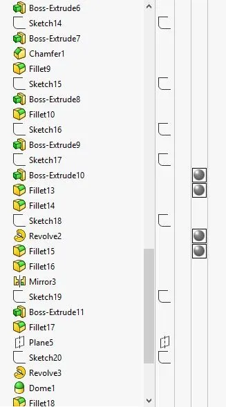
FEATURE MANAGER TREE - 4
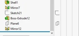
- ASSEMBLY OF AMERICAN YACHT
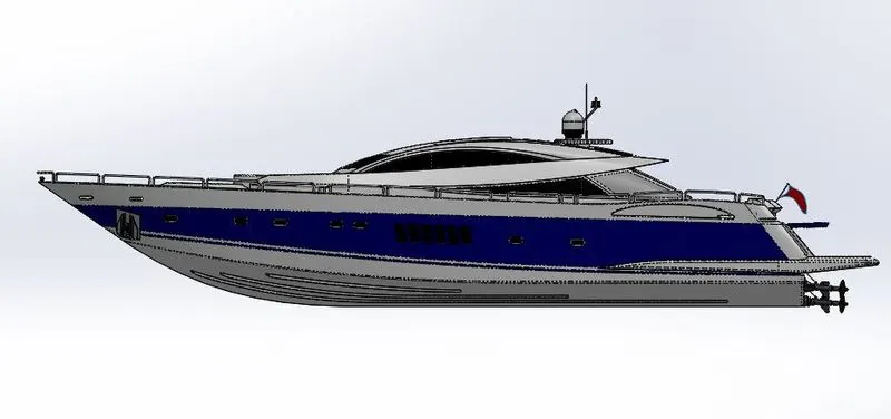
FRONT VIEW
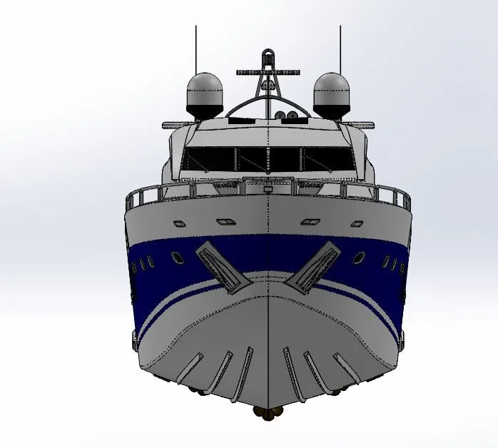
SIDE VIEW
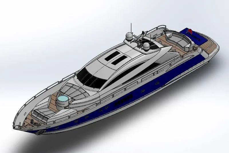
ISOMETRIC VIEW
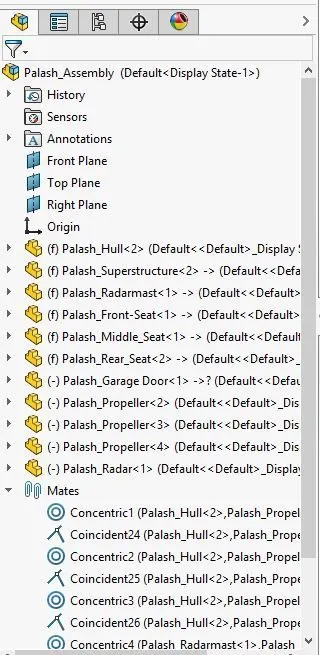
FEATURE MANAGER TREE - 1
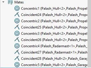
FEATURE MANAGER TREE - 2
PROJECT REPORT
MODELLING AND ASSEMBLY OF AN AMERICAN PREDATOR YACHT USING SOLIDWORKS
- INTRODUCTION: - A yacht is a sailing or power vessel used for pleasure, cruising, or racing. Doing CAD modelling using Solidworks 2019. Solidworks is extensively used for solid modelling as well as surface modelling. Nowadays Solidworks used in automotive, Aircraft and Ship manufacturing industries for modelling of heavy structures and components.
- OBJECTIVE: - Aim of the course is to CAD modelling and assembly of an American yacht using Solidworks software. After this course, learn many modules of Solidworks like surface modelling, assembly modules using different types of mates. Modelling of individual components and assembly of American Yacht.
- DESIGN METHODOLOGY/APPROACH: -
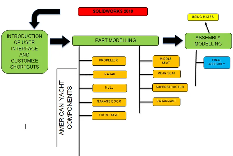
- DETAILED DESCRIPTION OF PROJECT: - Modeling and Assembly of American Yacht using Solidworks 2019. The approaches of modelling American Yacht are: -
- Firstly, Setup the blueprint of American Yacht.
- Part modelling of individual American Yacht components using sketching and solid & surfacing commands.
- After part modelling assemble the individual components using many types of different mates in assembly module.
- Setup the Blueprint in Solidworks is the initial process for modelling of any product with use of tracing the curves of product blueprint.
- During the ideation phase of design firstly we are working on a conceptual layout of our product by hand sketching or using Photoshop.
- After completing our concept sketch blueprint convert it to in JPEG format.
- Insert Blueprint JPEG file in Solidworks 2019 and setup the blueprint location editing coordinates on individual orthographic planes.
The basic steps involve for blueprint setup are: -
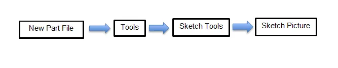
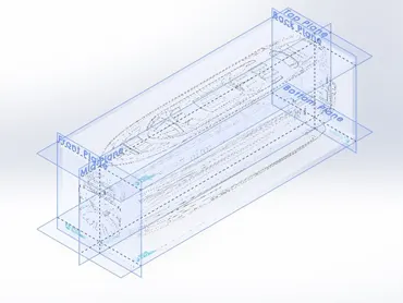
American Yacht Blueprint Setup
- After Blueprint setup, we will start Part modelling of individual components of American Yacht. Before start modelling of individual parts, use created part templates when we create new part file.
PART MODELLING OF AMERICAN YACHT COMPONENTS
1. PROPELLER :- Most marine propellers are screw propellers with helical blades rotating on a propeller shaft with an approximately horizontal axis. Propeller blades displace water, to create the forces that move a boat forward.
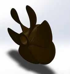
Propeller Image
- FEATURES USED TO CREATE PROPELLER
- Sketch
- Line
- Splines
- Revolve Boss/Base
- Fillet
- Circular Pattern
- Appearance
- SKETCH: - Sketch is a Two-Dimensional geometry (lines, Circles, Arc, ellipse) representation which use to convert 2D object into 3D.
- REVOLVE BOSS/BASE: - Revolves add or remove material by revolving one or more profiles around a centerline.
- FILLET: - Fillet is widely used command which can rounded the faces or edges of a part. You can fillet all edges of a face, selected sets of faces, selected edges, or edge loops.
- CIRCULAR PATTERN: - Use circular patterns to create multiple instances of one or more features that you can space uniformly around an axis.
- APPERANCE: - An appearance defines the visual properties of a model, including color and texture. Appearances do not affect physical properties, which are defined by materials.
PROCEDURE OF MODELLING PROPELLER: -
Create a round propeller shaft using revolving boss/base then make a propeller blade by lofted boss/base command and create more blades around shaft using circular pattern command. Provide fillets on edges to remove sharp corners of blades and at the end give appearance for good look.
2. RADAR: - Marine radars are X bandor S band radars on ships, used to detect other ships and land obstacles, to provide bearing and distance for collison avoidance and navigation at sea.
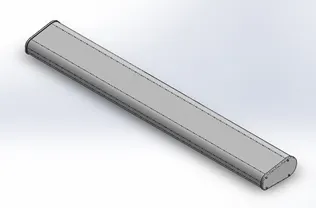
Radar Image
- FEATURE USED TO CREATE RADAR
- Sketch
- Text
- Extrude Boss/Base
- Split Line
- Fillet
- Appearance
- EXTRUDE BOSS/BASE OR CUT: - Extrude Boss/Base or Cut feature is use for adding or removing the material in part using any open or closed sketch profile.
- SPLIT LINE: - Split Line tool is used to project an entity (sketch, solid, surface, face, plane, or surface spline) onto other surfaces or curved/planar faces.
PROCEDURE OF MODELLING RADAR: -
Make a long bar using extrude boss feature then create a circular extruded boss feature on bar side face with a extrude cut pocket of polygon shape. Add more 3 extruded circular features using sketch driven pattern and make some fillets on edges. Cut some more round pockets and apply mirror command. Create a text “YACHT TUTORIAL” on radar bar surface and use split line command for separating the text from surface.
3. HULL: - A hull is the watertight body of a ship, boat and flying boat. The hull may open at the top (such as a dinghy), or it may be fully or partially covered with a deck. A top the deck may be a deckhouse and other superstructures, such as a funnel, derrick, or mast. The line where the hull meets the water surface is called the waterline.
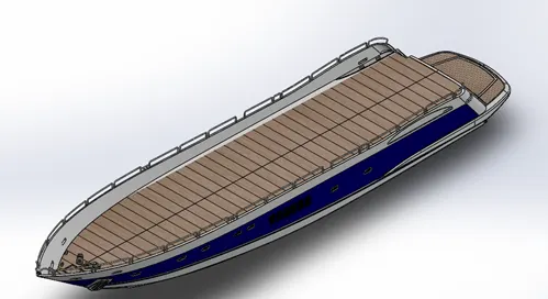
Hull Image
- FEATURE USED TO CREATE HULL
- Sketch
- Projected Curves
- Surface Loft
- Surface Trim
- Surface Extrude
- Knit Surface
- Filled Surface
- Shell
- Extrude Boss or Cut
- Fillet
- Chamfer
- Linear Pattern
- Revolve Boss/Base
- Sweep Boss/Base
- Combine
- Split
- Appearances
- SURFACE LOFT: - Create a plane for each profile section of the loft. Sketch the section profiles on the planes. You can create all section and guide curve sketches inside a single 3D sketch.
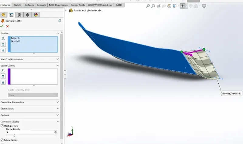
- KNIT SURFACE: - Use the Knit Surface tool to combine two or more faces and surfaces into one.
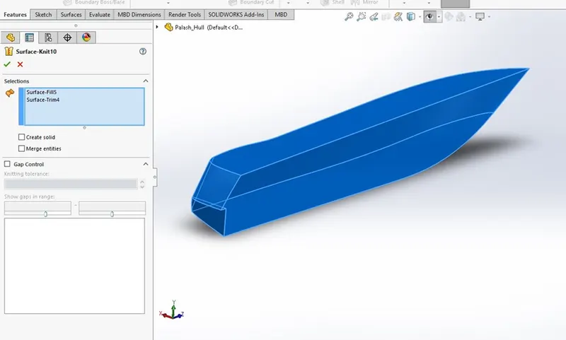
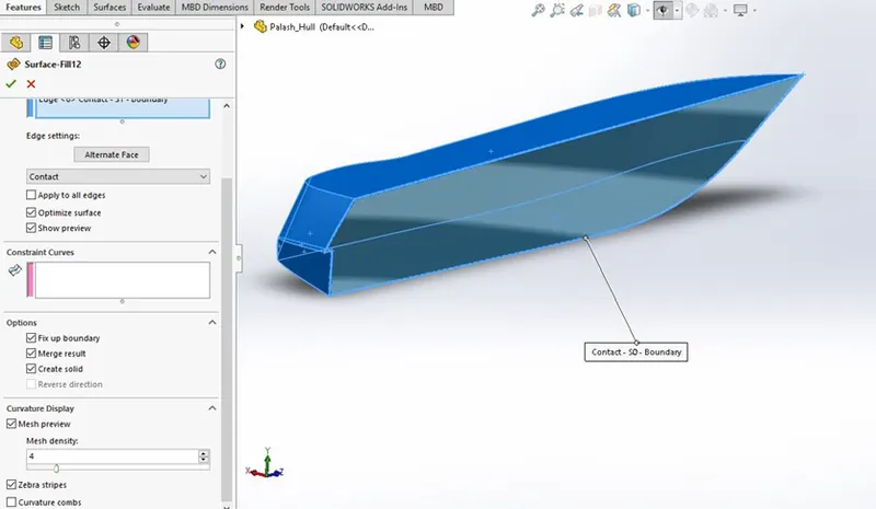
- FILLED SURFACE: - The Filled Surface feature constructs a surface patch with any number of sides, within a boundary defined by existing model edges, sketches, or curves, including composite curves.
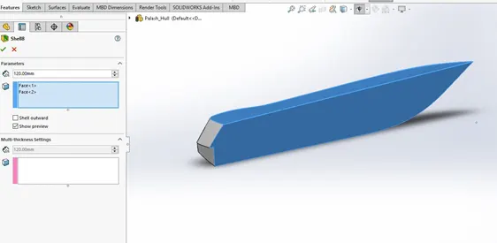
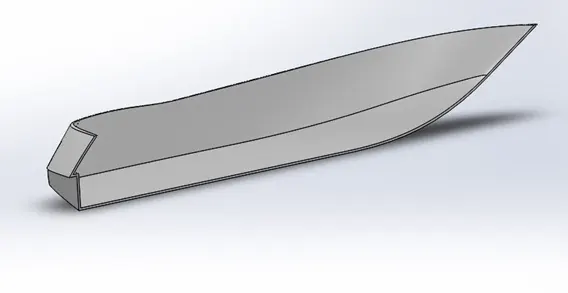
- SHELL: - The shell tool hollows out a part, leaves open the faces you select, and creates thin-walled features on the remaining faces. If you do not select any face on the model, you can shell a solid part, creating a closed, hollow model. You can also shell a model using multiple thicknesses.
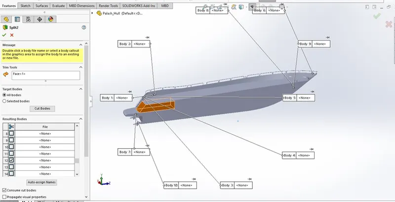
- SPLIT: - Use the Split feature to create multiple parts from an existing part. You can create separate part files and form an assembly from the new parts.
4. GARAGE DOOR: - Garage door is the hinged door which is fixed on hull.
Garage Door Image
- FEATURE USED TO CREATE GARAGE DOOR
- Sketch
- Extrude cut
- Shell
- Fillet
- Mirror
- Appearance
PROCEDURE OF MODELLING GARAGE DOOR
- Open garage door.sldprt file.
- Cut some portion using extrude cut command.
- Make hollow portion of door by shell command.
- Provide some fillets on edges.
- Create a door hinge hole using extrude cut.
- Mirror the door body about a plane with the help of mirror command.
- Text sketch “Yacht tutorial” & cut 8mm depth from door surface
- Apply appearance.
Front seat is places at front side of yacht for sitting and comfort journey of passengers.
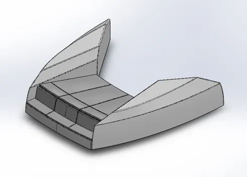
Front Seat Image
- FEATURE USED TO CREATE FRONT SEAT
- Sketch
- Surface Extrude
- Filled Surface
- Surface Sweep
- Surface Trim
- Surface Loft
- Knit Surface
- Revolve Boss/Base
- Extrude Cut
- Dome
- Appearance
DOME: - To create a convex on a surface at specifies distance from zero.
PROCEDURE FOR MODELLING FRONT SEAT
Sketch the front seat curves using splines by tracing the top blueprint and make surface model using surfacing commands like extrude, loft, trim & Dome.
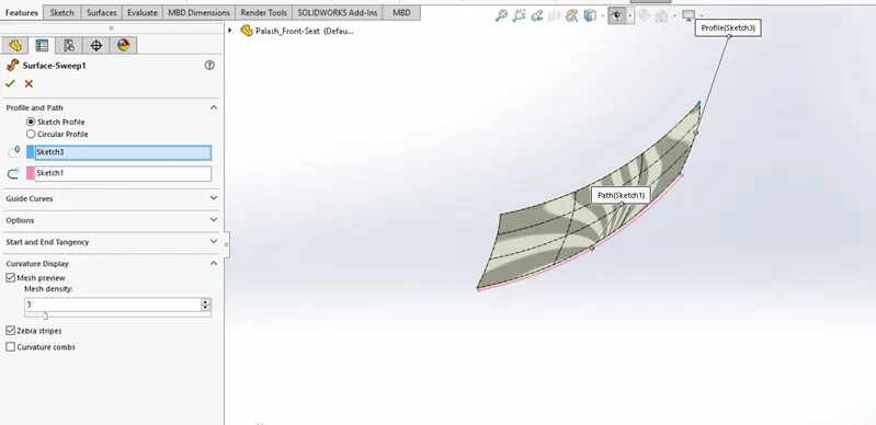
Surface Sweep
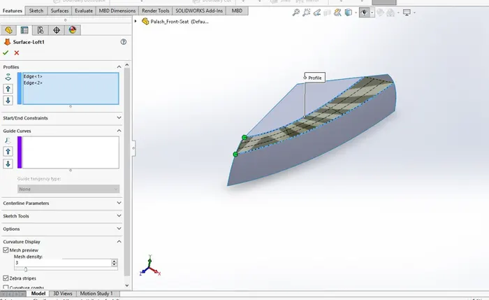
Surface Loft
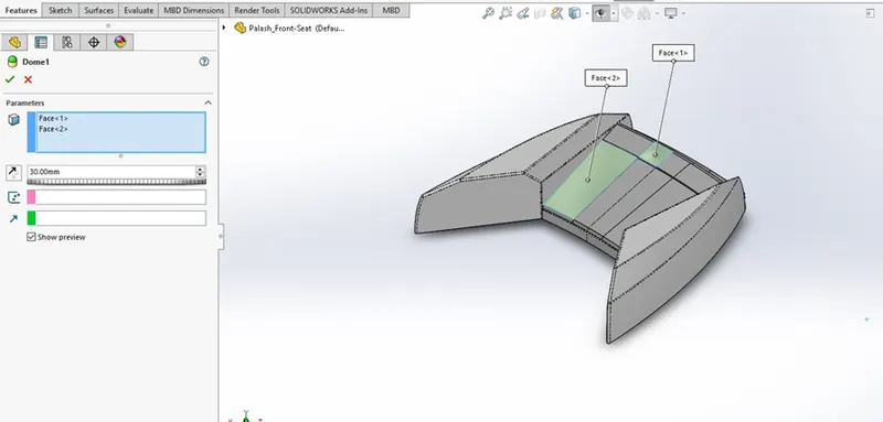
Dome
6. MIDDLE SEAT: - Front seat is places at middle seat of yacht for sitting and comfort journey of passengers.
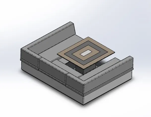
Middle Seat Image
- FEATURE USED TO MIDDLE SEAT
- Sketch
- Extrude Boss/Base
- Mirror
- Fillet
- Chamfer
- Appearance
PROCEDURE FOR MODELLING MIDDLE SEAT
Using extrude boss/base create some features by sketching and apply some chamfer and fillets on sharp edges then mirror solid bodies and at the end apply appearance.
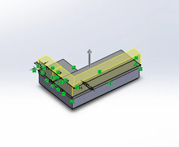
Extrude Boss/Base
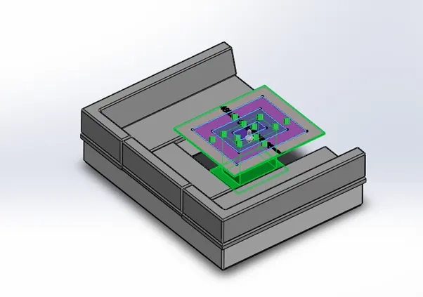
Extrude Cut
7. REAR SEAT: - Rear seat is places at middle seat of yacht for sitting and comfort journey of passengers.
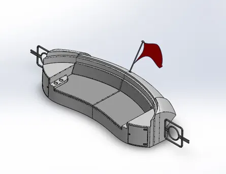
Rear Seat Image
- FEATURE USED TO CREATE REAR SEAT
- Sketch
- Splines
- 3D Sketch
- Surface Sweep
- Surface Trim
- Ruled Surface
- Knit Surface
- Extend Surface
- Surface Loft
- Surface Offset
- Sweep Boss/Base
- Mirror
- Revolve Boss/Base
- Appearance
- RULED SURFACE: - The Ruled Surface command creates surfaces that extend out in a specified direction from selected edges.
- EXTEND SURFACE: - You can extend a surface by selecting an edge, multiple edges, or a face.
- SURFACE OFFSET: - Surface offset is used for offsetting any face or surface at any distance from zero.
PROCEDURE FOR MODELLING REAR SEAT
Sketch the front seat curves using splines by tracing the top blueprint and make surface model using surfacing commands like Extrude, Loft, Trim, Offset Surface & Extend Surface.

Ruled Surface
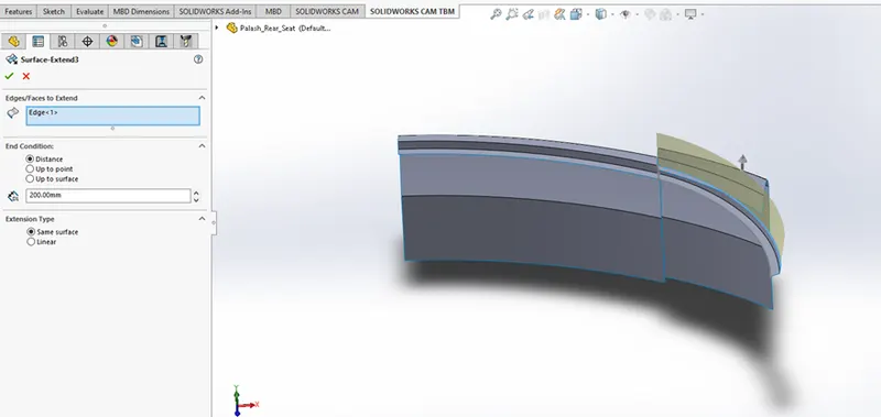
Extend Surface
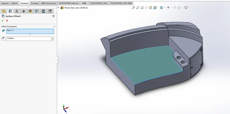
Offset Surface
8. SUPERSTRUCTURE: - The word comes from a combination of two Latin words, the Latin prefix ‘super’ means in addition or above or in excess of, whereas the stem word ‘structure’ means to build or to heap up. Thus, superstructure means to add a construction to an already existing structure. In ships this is the name given to the part of the ship that emerges from the deck.
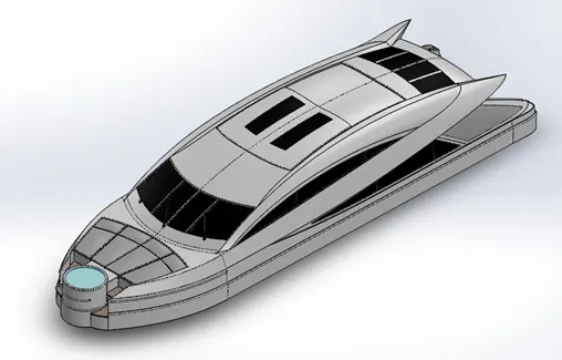
Superstructure Image
- FEATURE USED TO CREATE SUPERSTRUCTURE
- Sketch
- Splines
- Convert Entities
- Extrude Surface
- Swept Surface
- Knit Surface
- Ruled Surface
- Lofted Surface
- Filled Surface
- Trim Surface
- Projected Curve
- Dome
- Fillet
- Chamfer
- Appearances
PROCEDURE FOR MODELLING SUPERSTRUCTURE
Most of the surfacing command use for modeling of superstructure body. In which includes – Filled Surface, Lofted Surface, Surface Extend, Ruled Surface, Trim Surface and Swept Surface.
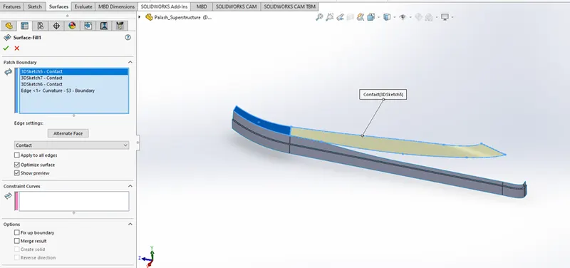
Filled Surface
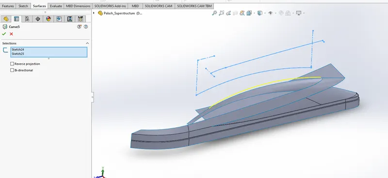
Projected Curve
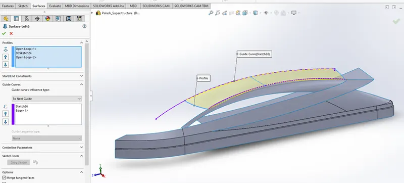
Lofted Surface
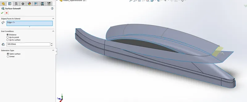
Surface Extend
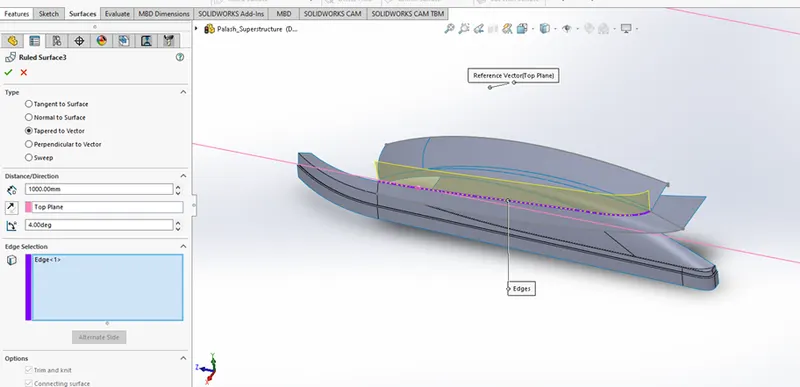
Ruled Surface
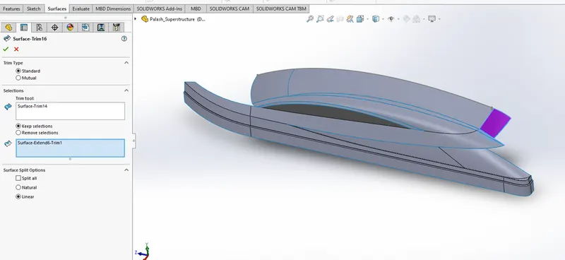
Trim Surface
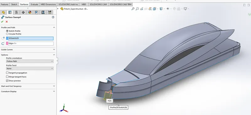
Swept Surface
9. RADARMAST: - They are electronic navigation instruments that use a rotating antenna to sweep a narrow beam of microwaves around the water surface surrounding the ship to the horizon, detecting targets by microwaves reflected from them, generating a picture of the ship's surroundings on a display screen.
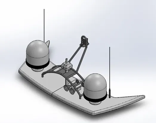
Radarmast Image
- FEATURE USED TO CREATE REAR WHEEL
- Sketch
- Extrude Boss/Base
- Revolve Boss/Base
- Dome
- Sweep Boss/Base
- Projected Curve
- Fillet
- Chamfer
- Mirror
- Shell
- Appearance
PROCEDURE FOR MODELLING RADARMAST
We have to create radar mast of yacht by using of solid feature commands like, Extrude Boss/Base, Revolve Boss/Base, Sweep Boss/Base, Shell, Dome and Mirror.
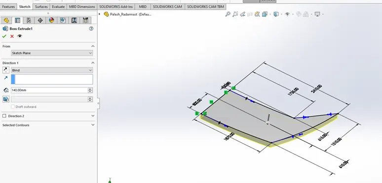
Extrude Boss/Base
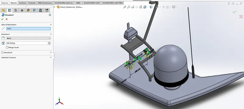
Revolve Boss/Base
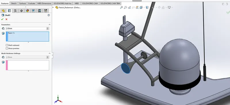
Shell
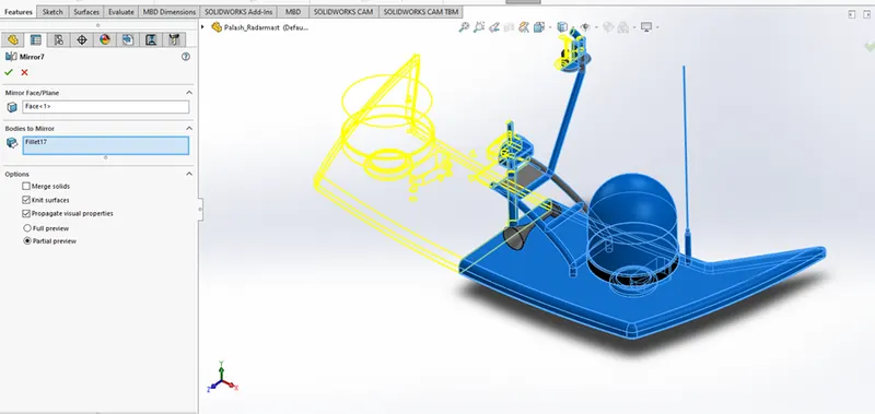
Mirror
ASSEMBLY MODELLING OF AMERICAN YACHT
Assembly modeling is a technology and method used by computer aided design and product visualization computer software systems to handle multiple files that represent components within a product. Components can be positioned within the product assembly using absolute coordinate placement methods or by means of mating conditions. Mating condition are definitions of the relative position of components between each other. The components within an assembly are represented as solid or surface models.
Assembly approach in computer aided design: -
- Bottom-Up assembly approach
- Top-Down assembly approach
- ASSEMBLY OF AMERICAN YACHT
Assembly of American yacht is the process of joining the individual yacht components using constraints.
Types of Constraints: -
- Concentric
- Coincident
- Tangent with planes
- Parallel
- Perpendicular…..etc.
In Solidworks use mate option for doing any assembly.
There are 2 types mate used: -
- Mechanical Mates
- Advance Mates
PROCEDURE FOR ASSEMBLY OF AMERICAN YACHT
Call the superstructure from the working directory and fix it. After fix the superstructure call individual component of yacht respectively - Front Seat, Radarmast, Middle Seat, Rear Seat, Garage Door, Propeller and Radar.
Note: - In some components don’t need to apply mates because positions of these components already specified during part modeling.
Images of Assembled American Yacht:
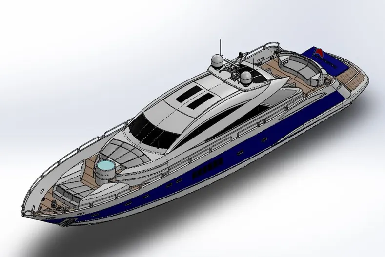
ISOMETRIC VIEW
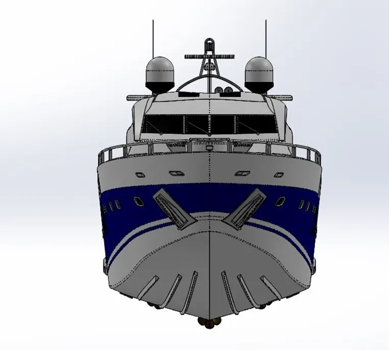
FRONT VIEW
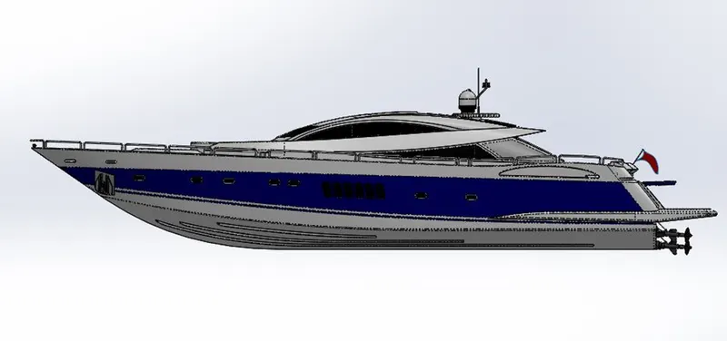
SIDE VIEW
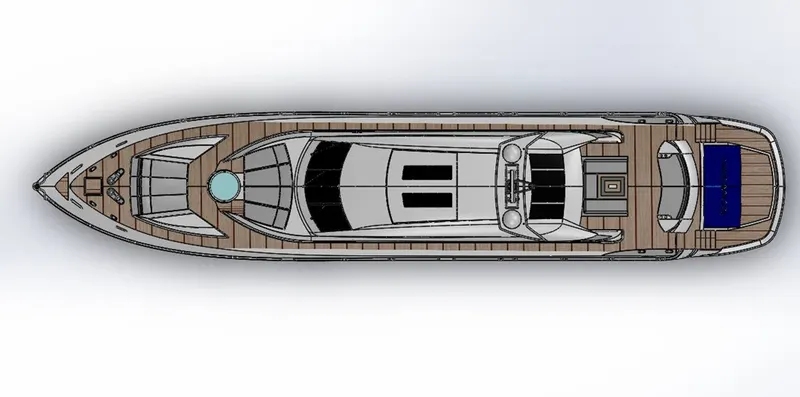
TOP VIEW
- CONCLUSION
- Knowledge of American Yacht components modeled by converting sketch into solid model.
- Learn assembly of the all components using types of mate in assembly environment.