Week 9 - Challenge 1 - Base Bracket Design
AIM:
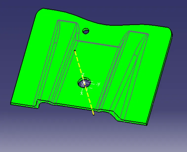
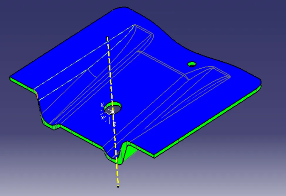
To create a solid component of thickness 2.5mm with the given Class A Surface as input, while determining the tooling axis and clearing the draft analysis.
CLASS A SURFACE INSPECTION:
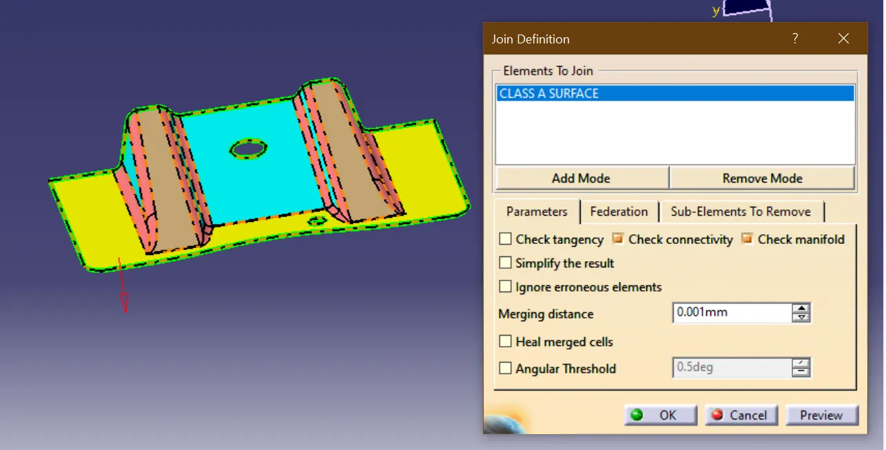
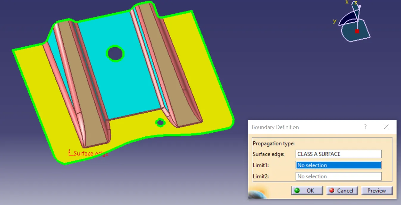
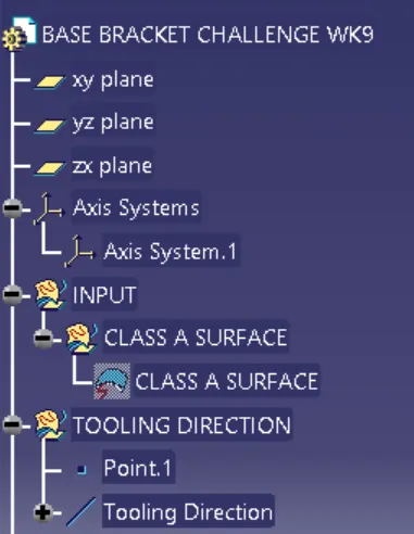
- The given Class A Surface is inspected visually for any connectivity errors using the join command and the boundary command.
- Once the surface check is completed and there are no errors then the next step is carried that is tooling axis determination.
- If not, the feedback is sent to the styling team to do the necessary corrections and refinements.
TOOLING AXIS / DIRECTION DETERMINATION:
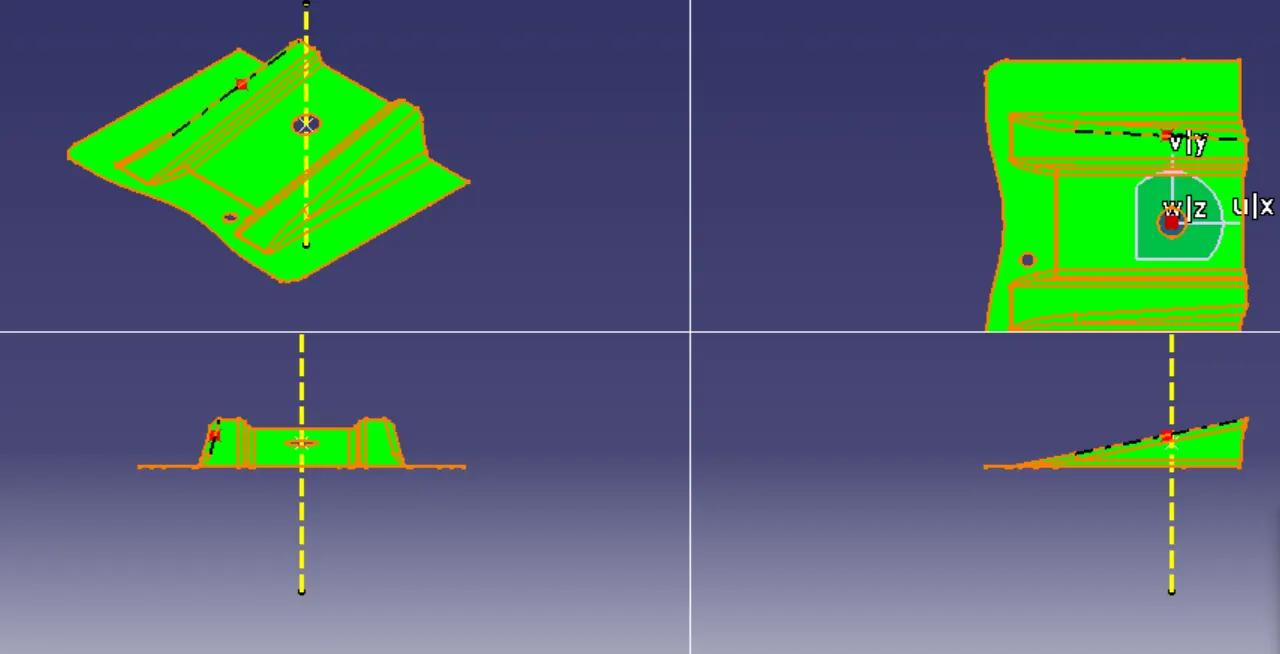
- There are many ways to determine the tooling axis and one way is to check the given surface in X Y and Z axes.
- The other method is to check for any holes in the surface the line/axis that runs perpendicular to that hole will be a possible tooling axis.
- Another method is by creating intersection with the help of a dummy tooling axis system and creating bisecting lines and determine the tooling axis.
Steps involved in intersection and bisecting method:
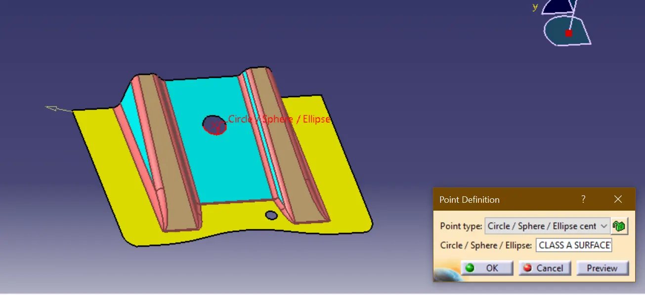
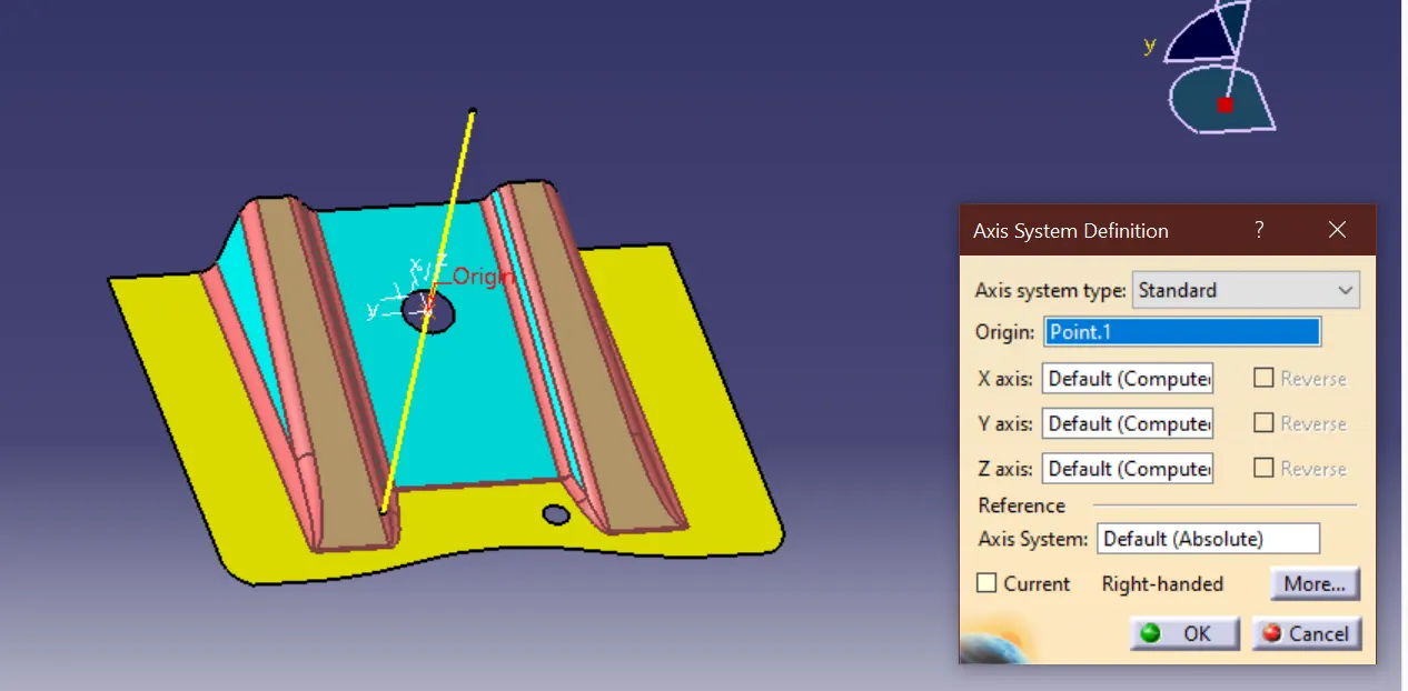
- Create a point for the class A-surface, since the surface has two holes, the center point of either of the holes can be used.
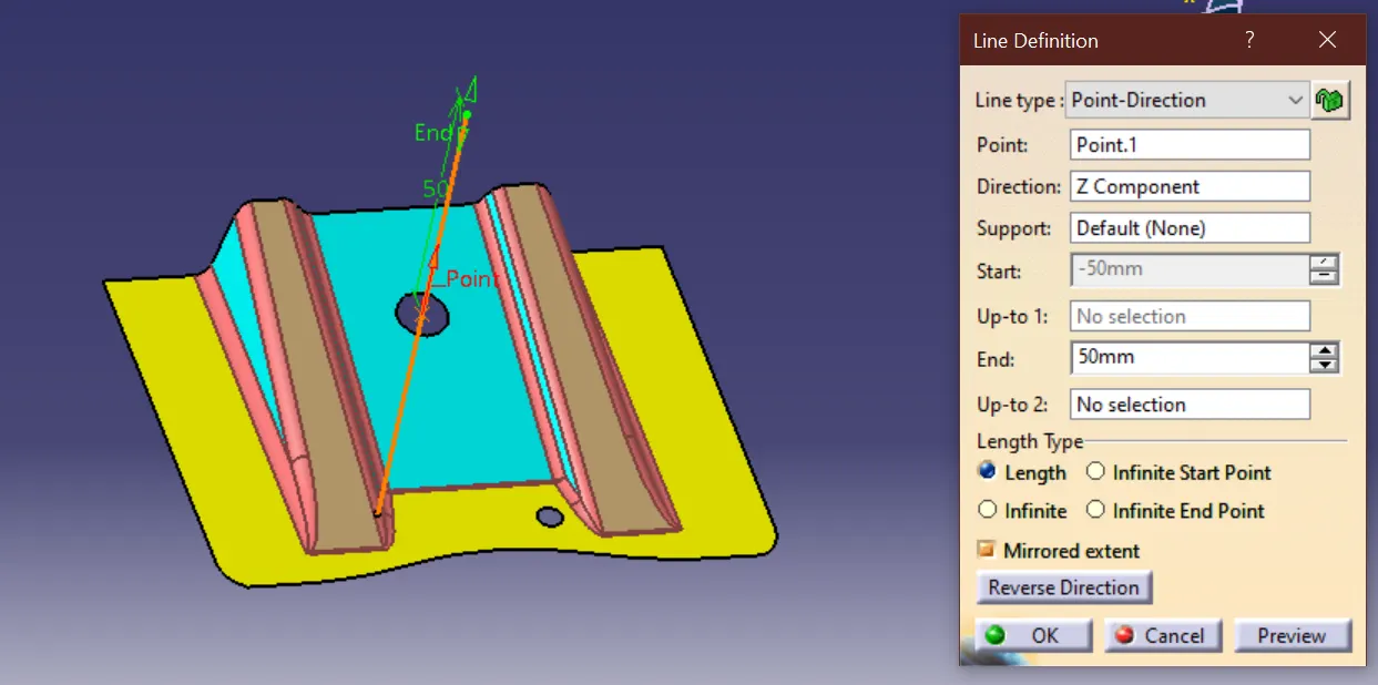
- Create a dummy tooling axis along Z-direction with that point.
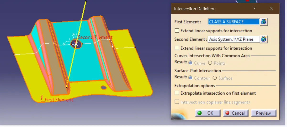
- Create an axis system with that point which is not current and create an intersection using the YZ plane of the axis system.
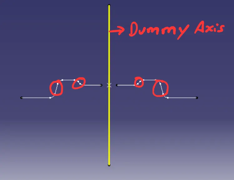
- Select the curves from the intersection that might cause potential draft issues by visually inspecting (almost parallel to the dummy axis), and create lines with their vertices using point to point type in line command.
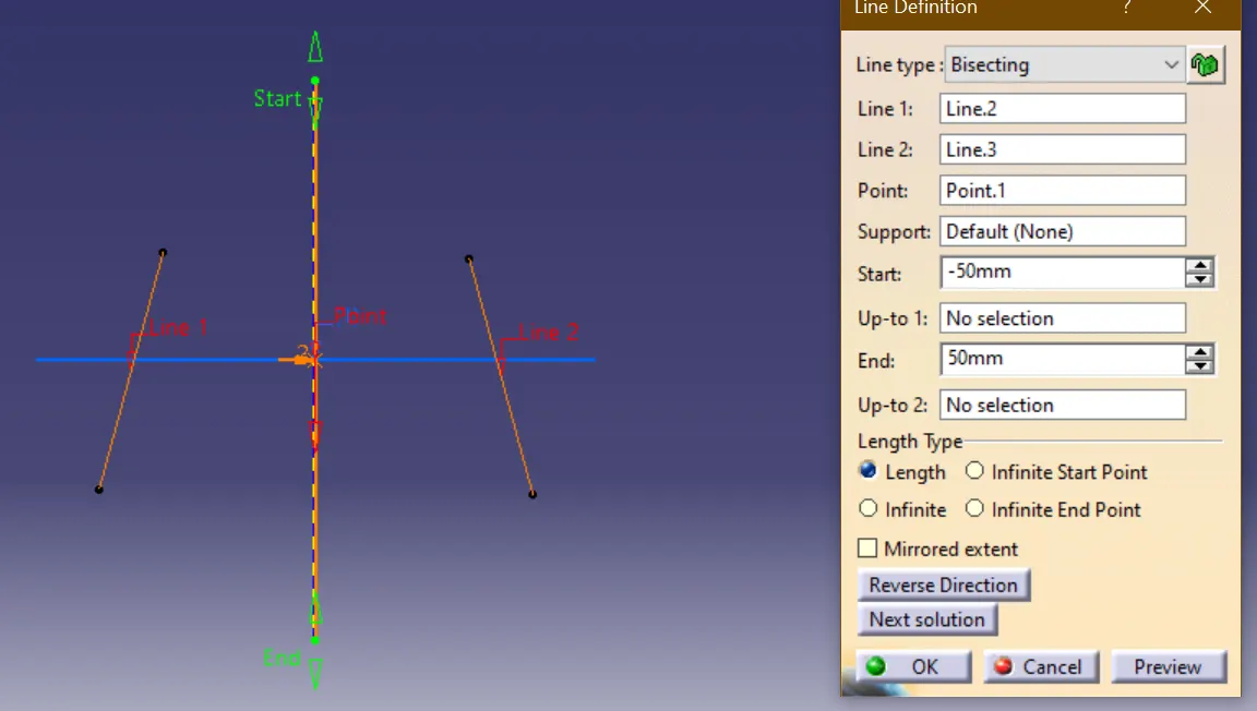
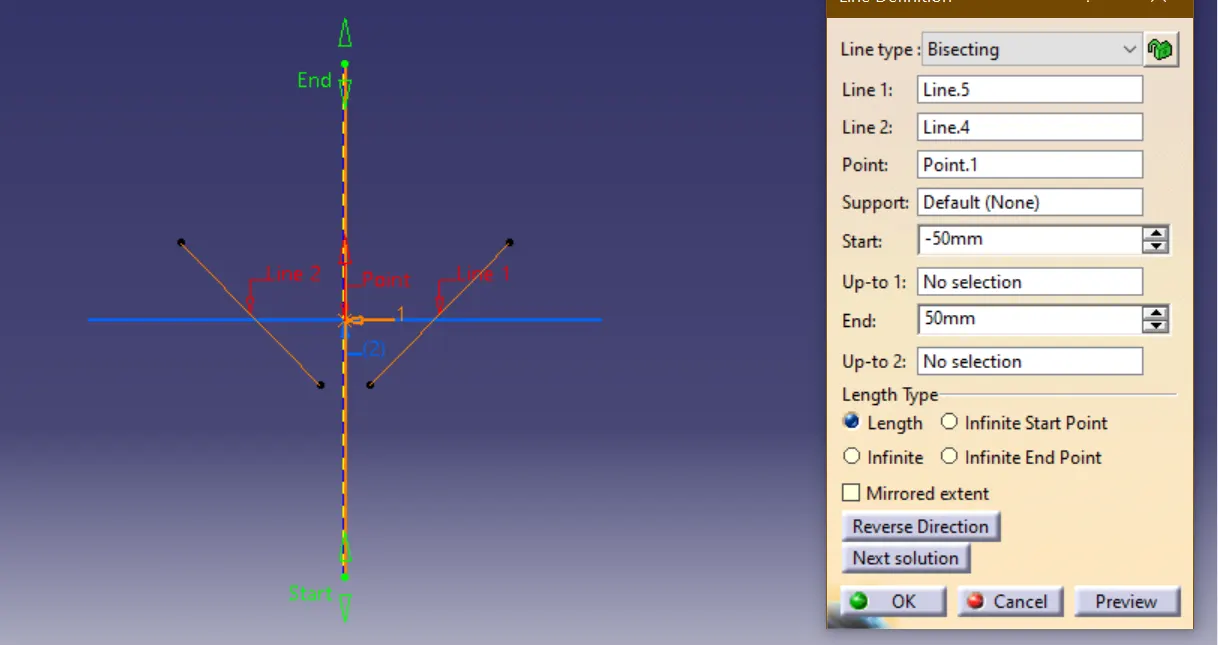
- Create a line that bisects the lines created and select the required direction.
- Repeat the above steps in the XZ plane of the axis system if required.
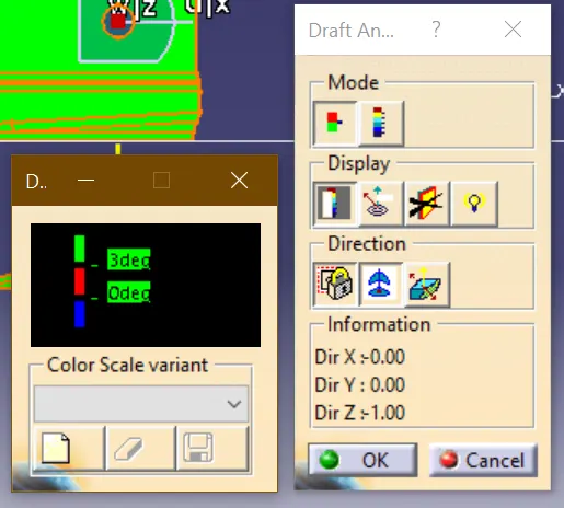
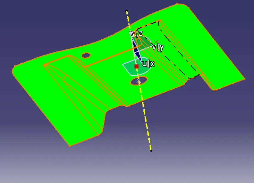
- If the 3° draft is cleared then, can proceed to the next step which is B-Surface creation which is nothing but the functional offset of the Class A-Surface.
CLASS B SURFACE CREATION:
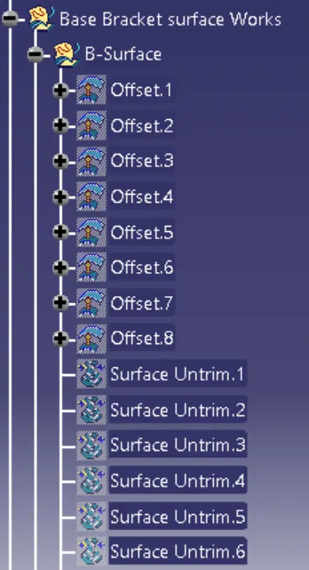
- The given Class A-Surface is offset to a certain value (here 2.5mm).
- While offsetting, some features like fillets and twisted surface might cause errors and thus it is offset without those and can be given in the later stages.
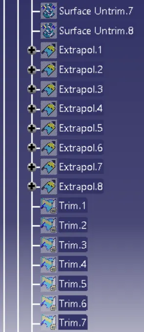
- The surfaces of the A-surface is offset is individually and is trimmed/joined together.
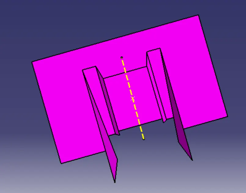
CLASS C SURFACE CREATION:
- Once after B-surface is complete, a closing surface is created in between the A-surface and B-surface.
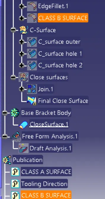
- The C-surface is nothing but the closing surface that closes the A and B surfaces to give a closed body of surfaces out of which a solid can be formed by using the close surface command.
- For creating C-surface, sweep surface command is used with draft direction option and the boundary of the A-surface is given as profile input and the tooling direction/axis is given as draft direction input with 3° or more draft angle and the suitable sector which is towards the B-surface is selected.
CLOSE BODY SURFACE CREATION:
- After creating the C-surface, the A and C surfaces are joined.
- And the B-surface is trimmed with the join.
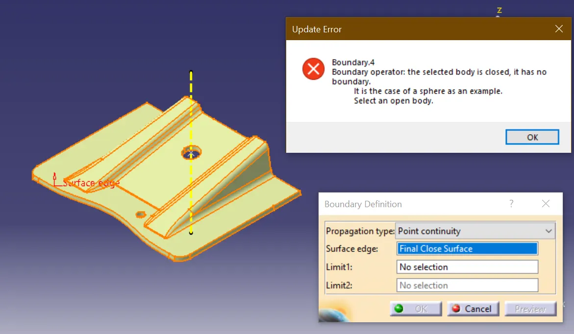
- To double check that the close surface is formed properly, boundary command is used and if the command gives an error like, ‘the selected surface has no open boundary’ then the surface properly closed without any defects.
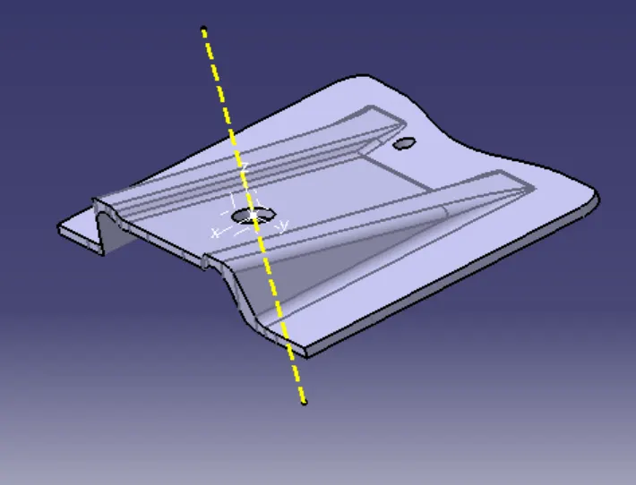
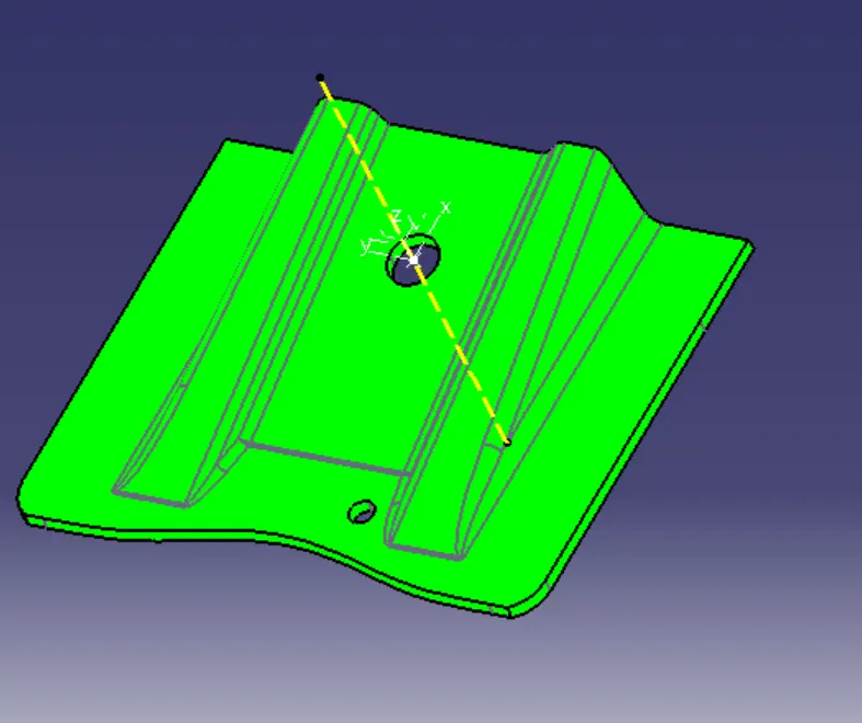
- To convert the surface to a solid close surface command in part design workbench is used.
 |
|---|
 |
 |
 |
 |