Week 9 - Challenge 1 - Base Bracket Design
Base Bracket Design
AIM: To create the Base Bracket Plastic component through the given Class-A surface and perform draft analysis for component.
Introduction
Tooling Axis
- The Tooling Axis is to show in what direction does the core and cavity moves.
- It also created to give a draft angle for the final solid part.
Draft Analysis
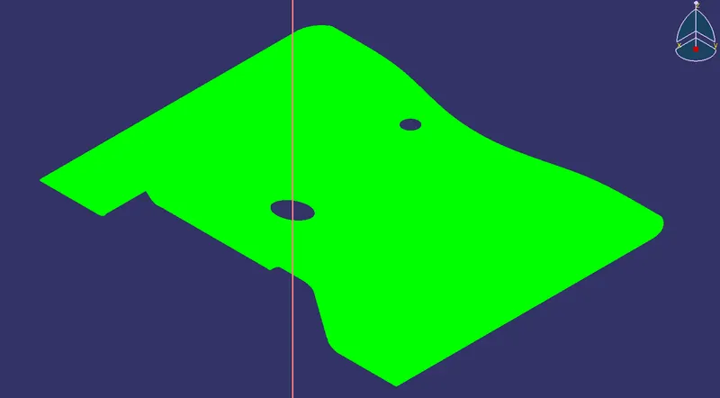
- The draft analysis is done on the basis of the Tooling Axis in order to find whether the final product is done as per the Design rules.
- The Draft angle which is assigned to the Tooling Axis defines the analysis.
- The Nominal Draft angle for the plastic product is 3 degree.
Class A
- Class A is the aesthetic surface.
- Class A is created on the basis of a concept sketch or by the predefined shape on basis of the design engineer and customer requirement.
- Class A is given to the Product design engineer in order to get the final solid part.
Class B
- Class B is the surface that is created by the product design engineer in order to get the final product from the class A surface.
- Class B is created based on the thickness that the final solid part should be.
- In other words, Class B is an Extended version of Class A with some thickness gap between them.
Class C
- Class C is the surface that is designed by the product design Engineer.
- Class C is created inbewteen Class A and Class B in order to connect them.
Procedure
Creation of Tooling Axis
- Tooling axis is create by using bisecting method.
- In this, a reference lines are created and with the help of bisecting line and point.
- The axis is created by extrecting the hole and creating a point at the center of hole.
- A plane is create at the cnter point and took a intersection. Drawn two lines with the reference of the intersecton and creted an axis by using bisecting line.
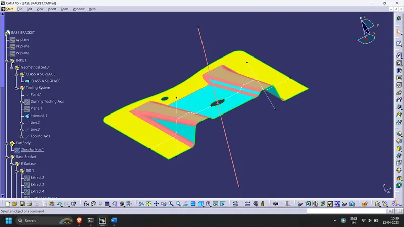
Draft Analysis of Class A Surface:
Creation of Class B Surface:
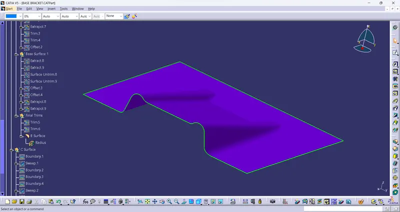
To create the Class B surface, faces are extracted and untrimmed from Class A seperately.
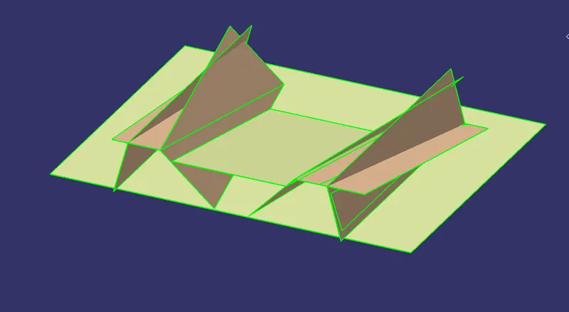
All the untrimmed faces are extrapolated with curvature continuity.
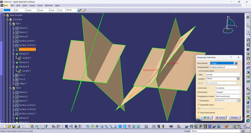
As the thickenss of component is 2.5 mm, All the extrapolated faces are offsetted by 2.5 mm and trimmed the faces together.
And the B surface is ready
Creation of Class C Surface:
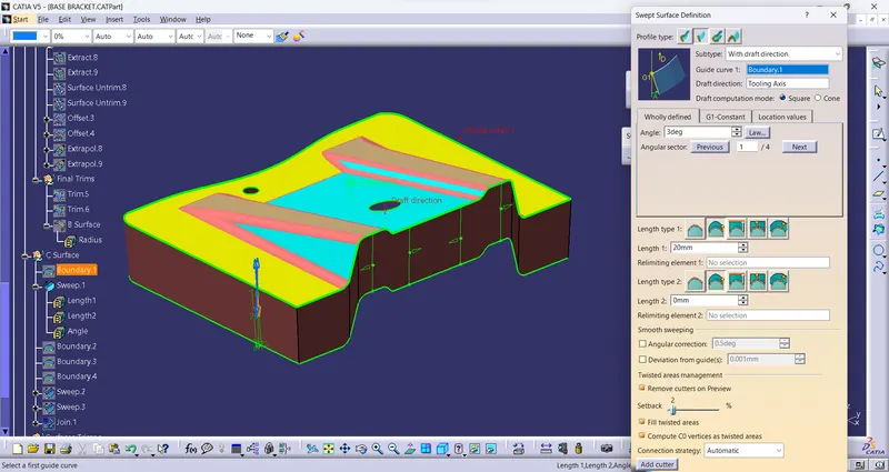
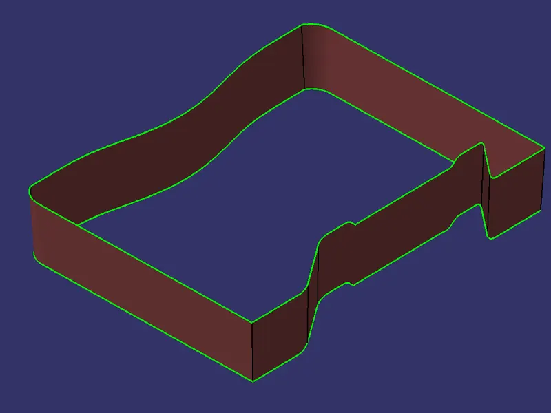
To create C surface, Boundary is taken from class A surface.
Using the boundary as guiding curve and tooling axis as draft direction,swept the surafce. This is done using Draft with direction option.
Class C surface is created.
Final Operations:
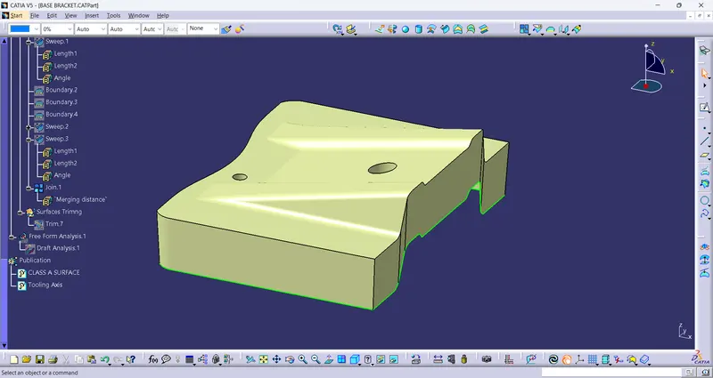
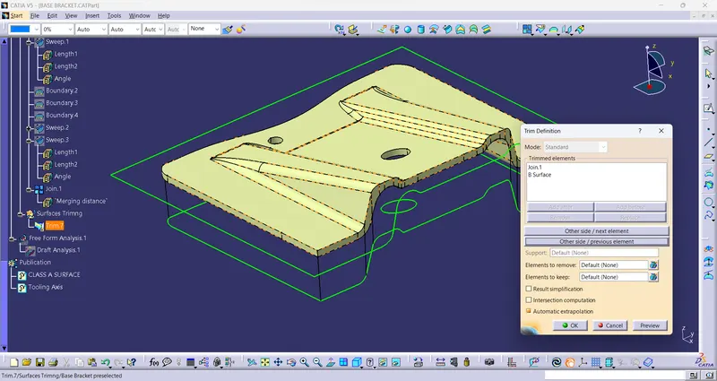
After creating Class B and Class C Surface, Class C surface is joined with Class A surface. And this output is trimmed with the Class B Surface.
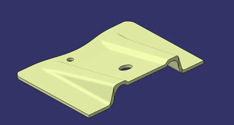
Creation of Solid Body:
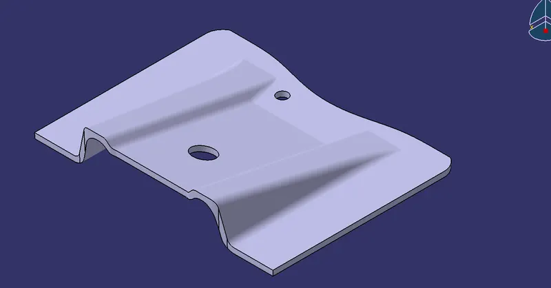
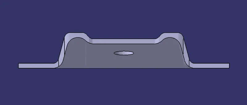
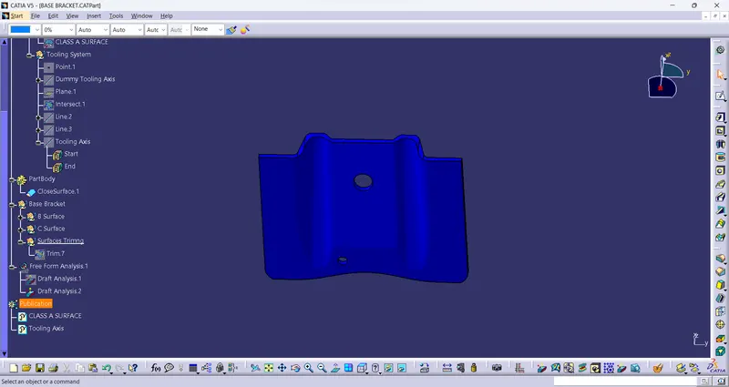
Solid Body is created using Close Surface option available in Part design workbench.
closed surface tool is used to convert the plastic design model to solid form.
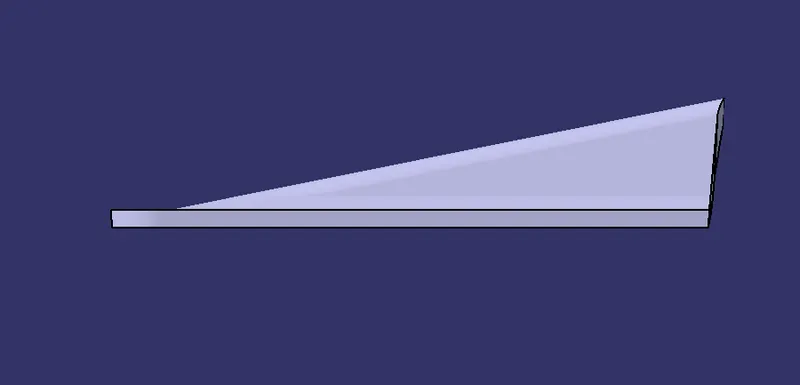
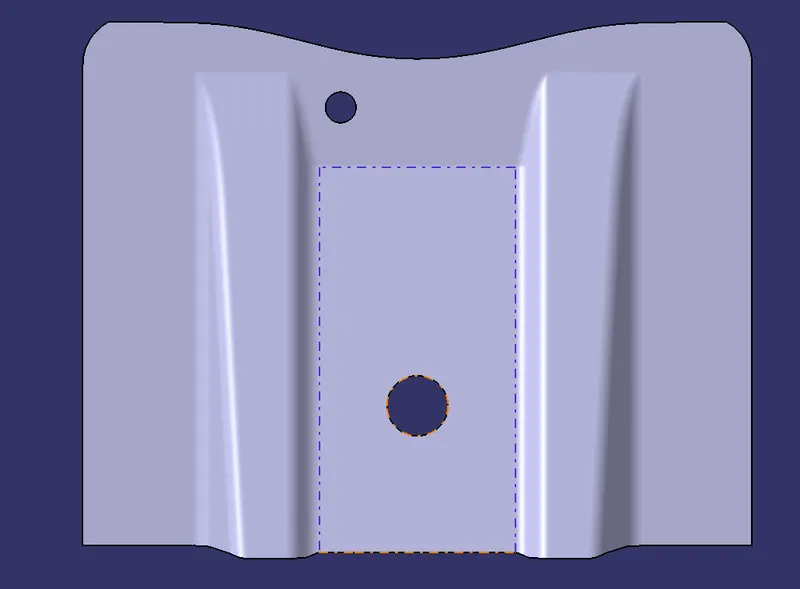
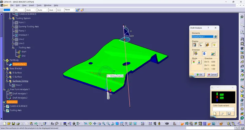
Draft Analysis of Final Plastic Component:
After the creation of solid model, draft analysis is performed on the final model.
Conclusion:
1.Class B and Class C is made out of the given Class A using PART and Surface design workbench.
2.Created Tooling axis with the help of bisection methoid
3.Performed Draft analysis on given Class A Surface and Final Solid model.